Project 1_Comparative study of different storey buildings for Seismic forces
PROJECT-1:
Comparative study of different-storey buildings for Seismic forces
AIM:
Comparative study of different-storey buildings for Seismic forces
INTRODUCTION:
ETABS software is a computer program used by engineers and architects to design and analyze structural systems. ETABS is a three-dimensional finite element analysis and design program that can be used to analyze and design buildings, bridges, and other structural systems.
ETABS software is a powerful tool that can be used to design and analyze structural systems. The software can be used to design buildings, bridges, and other structural systems. The software can also be used to analyze the behaviour of structural systems under various loading conditions.
The ETABS software can be used to perform a variety of analyses, including linear static analysis, nonlinear static analysis, dynamic analysis, and response spectrum analysis. The software can also be used to generate reports and graphs that show the results of the analyses.
The ETABS software is a valuable tool for engineers and architects. The software can be used to design and analyze structural systems quickly and easily. The software is also easy to use, which makes it a valuable tool for anyone who wants to design and analyze structural systems.
PROCEDURE:
Factors influencing the dynamic characteristics of a building:
- Buildings oscillate during earthquake shaking. The oscillation causes inertia force to be induced in the building.
- The intensity and duration of oscillation, and the amount of inertia force induced in a building depend on features of buildings, called their dynamic characteristics, in addition to the characteristics of the earthquake shaking (beyond the control of an engineer) itself.
- The important dynamic characteristics of buildings are modes of oscillation and damping (assumed constant in most practical cases). A mode of oscillation of a building is defined by the associated Natural Period and Deformed Shape in which it oscillates.
- Every building has a number of natural frequencies (how many?), at which it offers minimum resistance to shaking induced by external effects (like earthquakes and wind) and internal effects (like motors fixed on it).
- Each of these natural frequencies and the associated deformation shape of a building constitute a Natural Mode of Oscillation.
- The mode of oscillation with the smallest natural frequency (and largest natural period) is called the Fundamental Mode; the associated natural period T1 is called the Fundamental Natural Period.
- Regular buildings held at their base from translation in the three directions, have two fundamental translational natural periods, Tx1 and Ty1, associated with itstheirrizontal translational oscillation along X and Y directions, respectively, and one fundamental rotational natural period Tθ1 associated with its rotation about an axis parallel to the Z axis.
Factors influencing the Natural Period of a building:
BUILDING-A:(2 STOREY BUILDING):
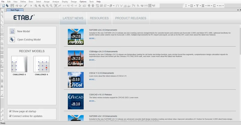
1. Open ETABS software.
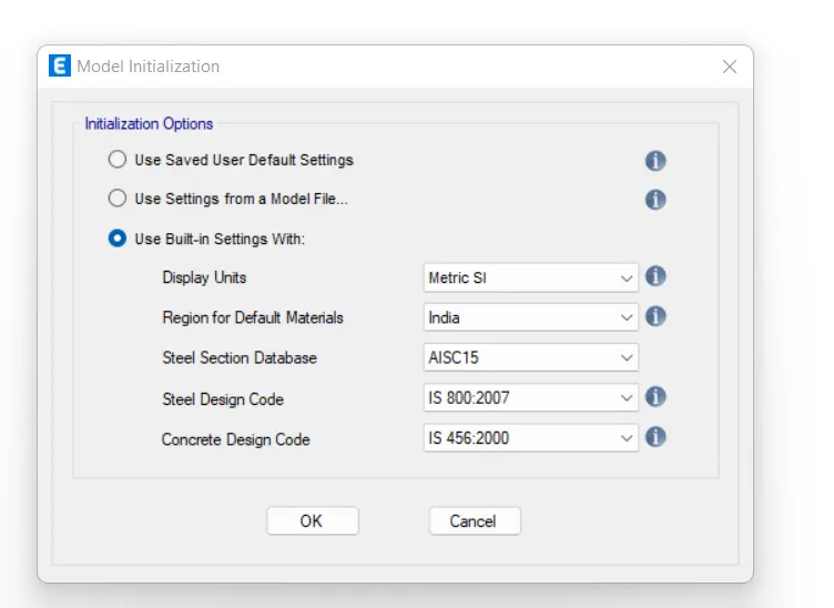
2. Now open it new model and selected the proper metric units and also select the codes IS800 for Steel and IS456 for concrete.
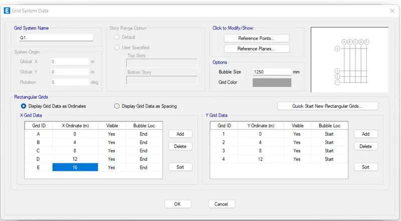
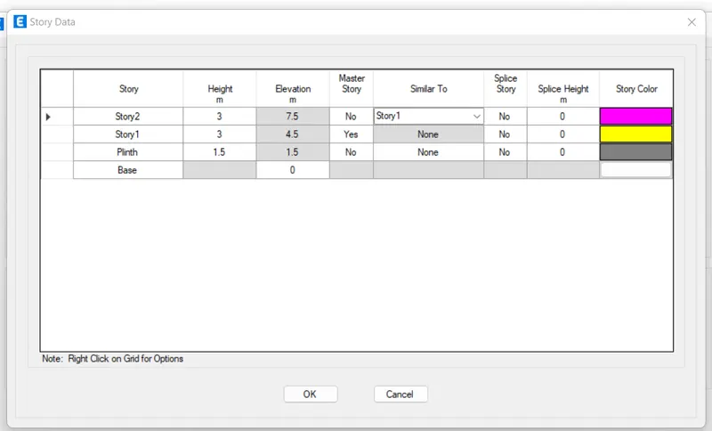
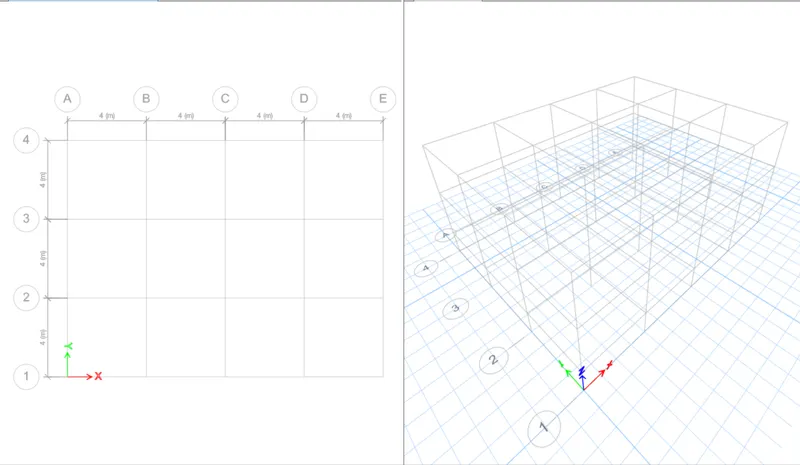
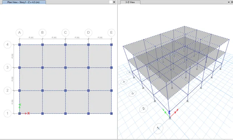
3. After that Create the Grid spacing Data and mentioned their storeys.
4. Now go to the define option and select materials and add it.
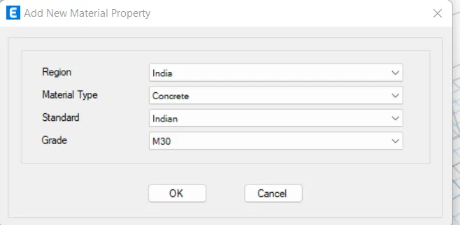
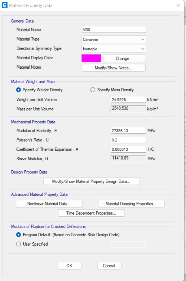
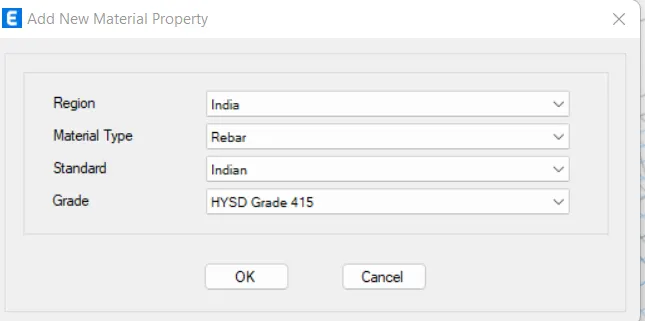
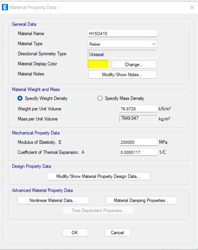
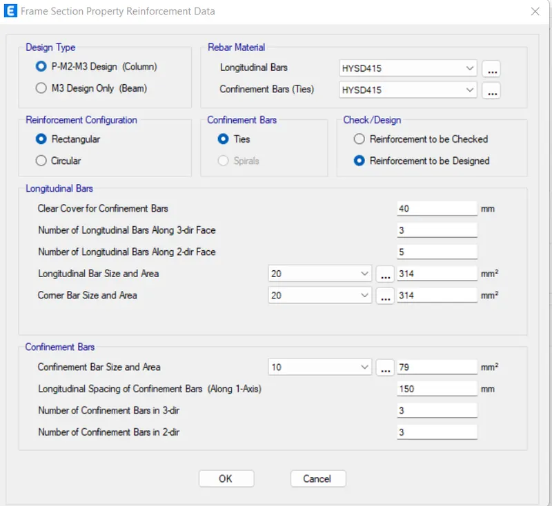
5. After that go to section properties to select Beams, columns and slabs to add it.
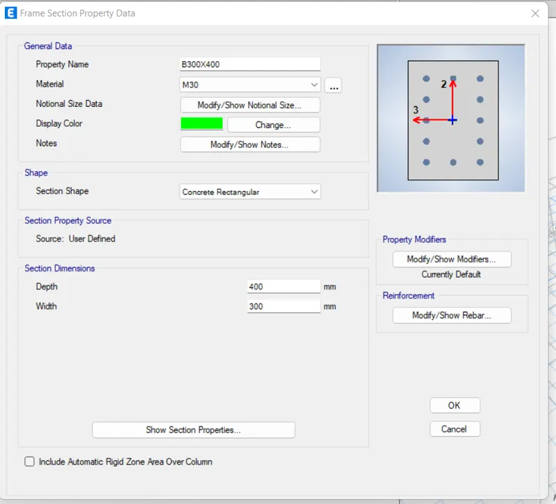
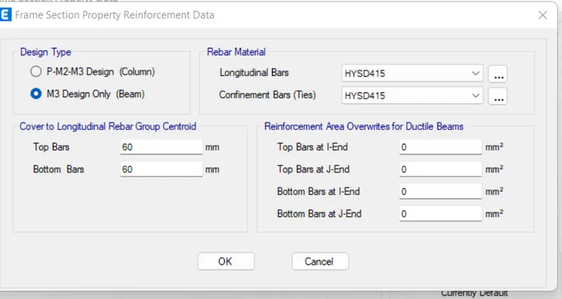
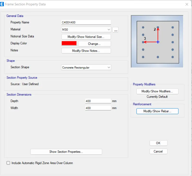
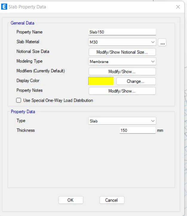
6. Now go to slab sections and to mentioned slab thickness of 150mm.
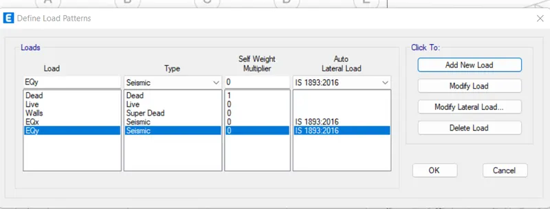
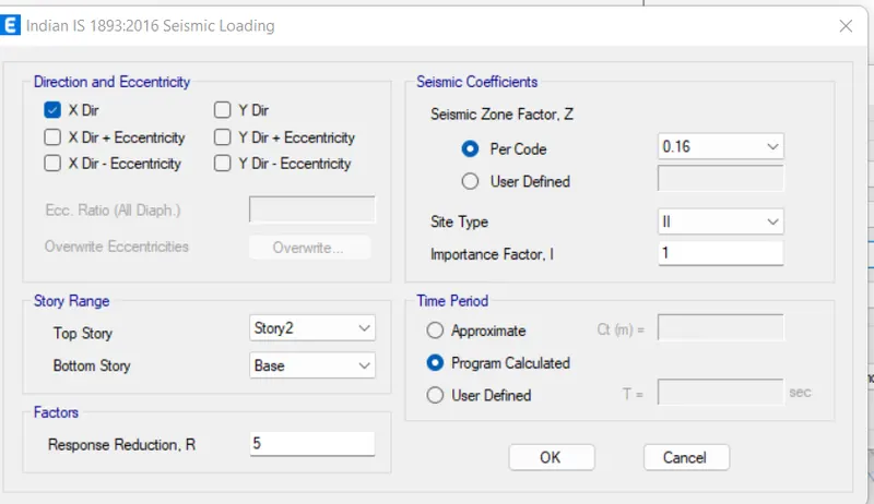
7. Now Go to Load patterns and create the loads.
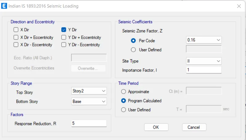
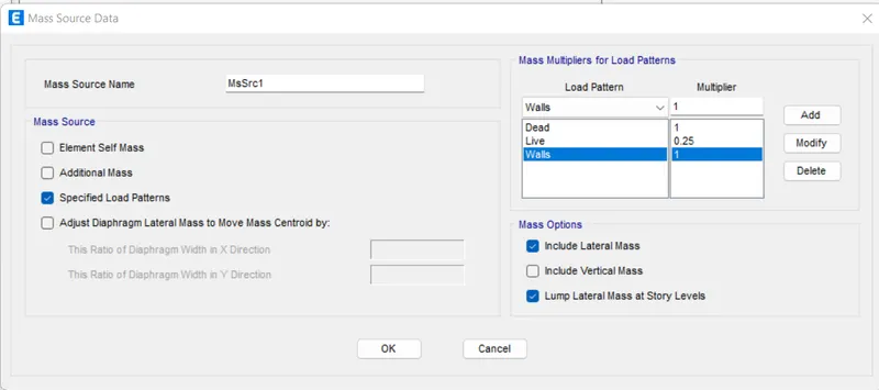
8. Now Go to the mass source and create the mass source data respectively.
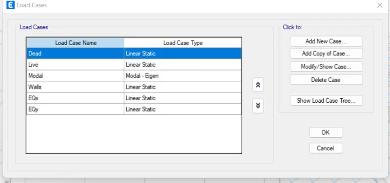
9. Now check the load cases.
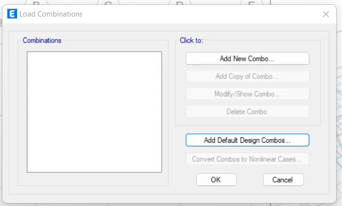
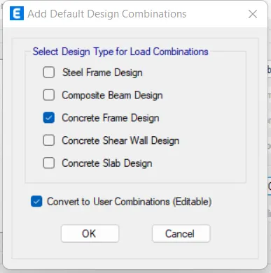
10. Now create the load combinations for the concrete frame design.
11. Now go to create column, Beam and slab modelling and draw them for all floors.
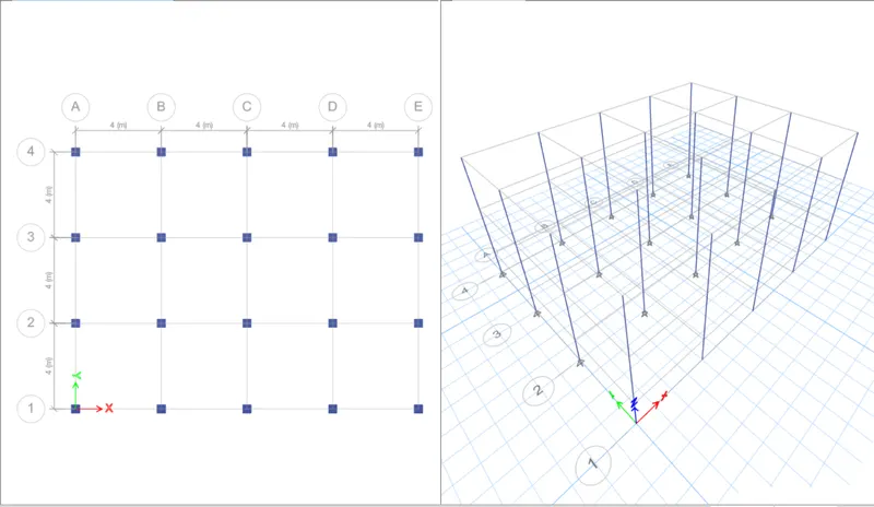
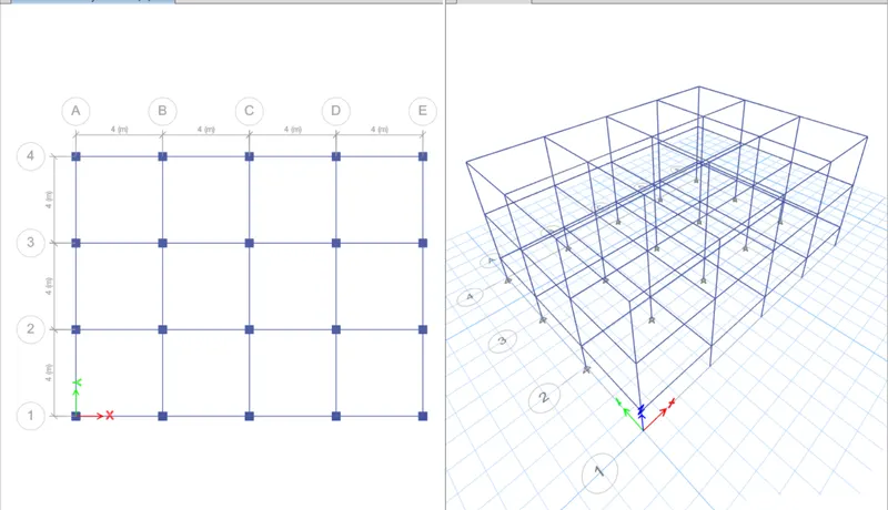
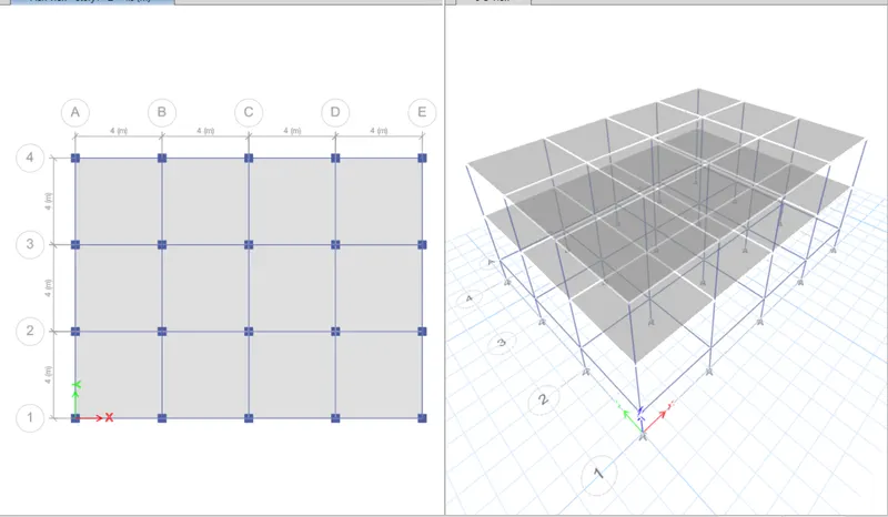
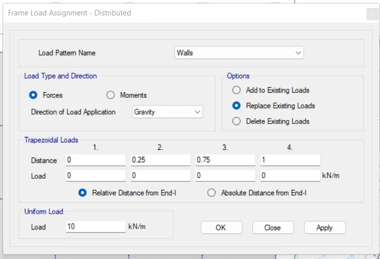
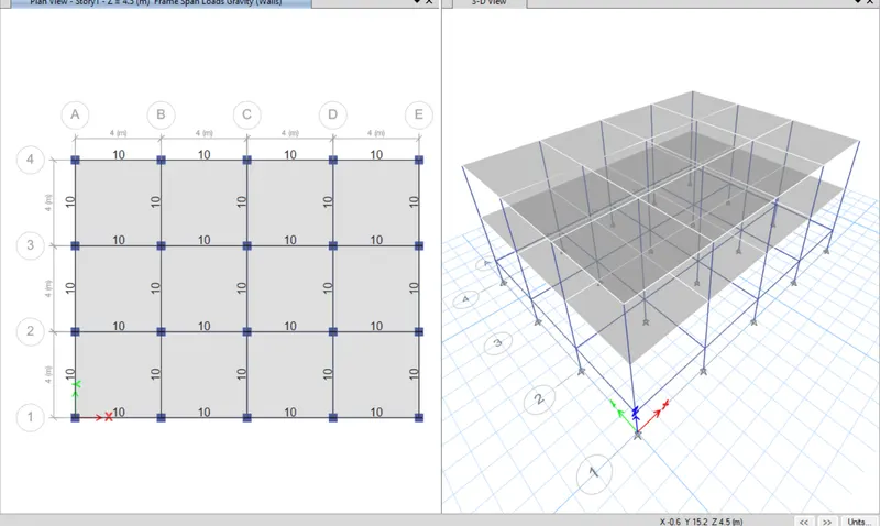
12. Now assign the loads to select properties to choose beam property to select all the beams in the modelling. Assign the loads with a wall-type load of 10Kn/m.
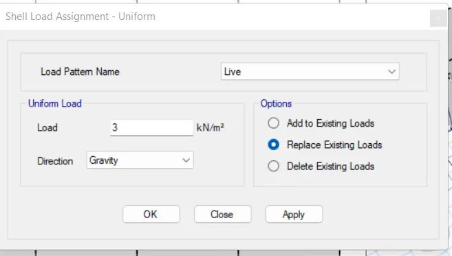
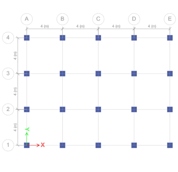
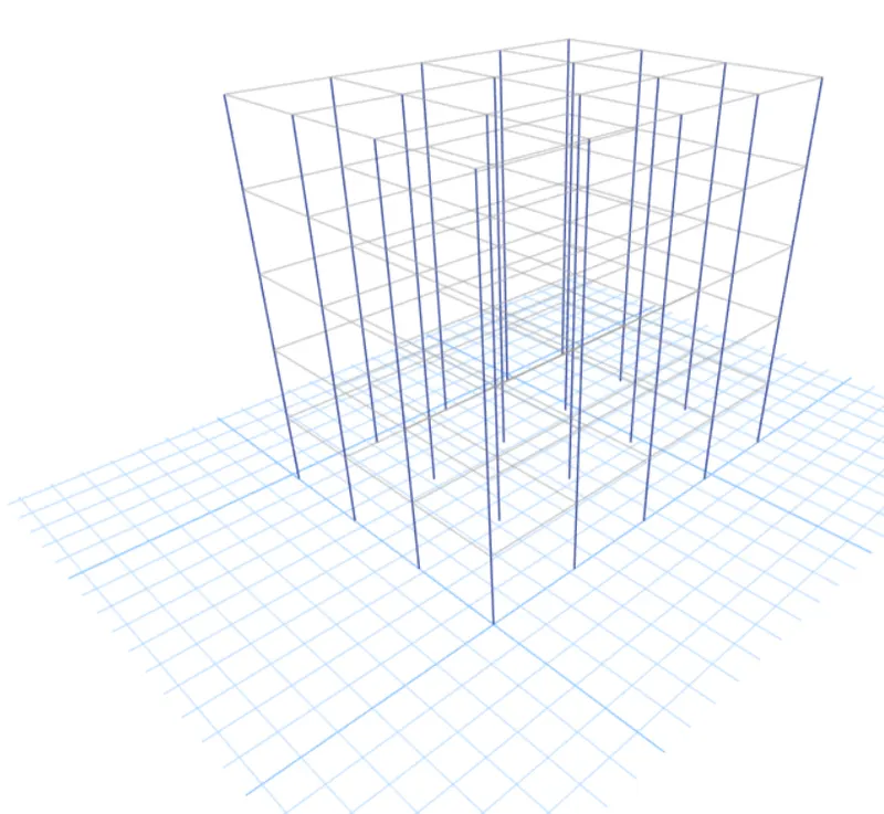
13. After that select the slab and assign the load 3Kn/m2 respectively.
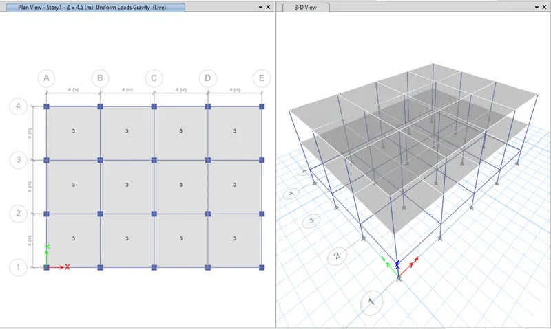
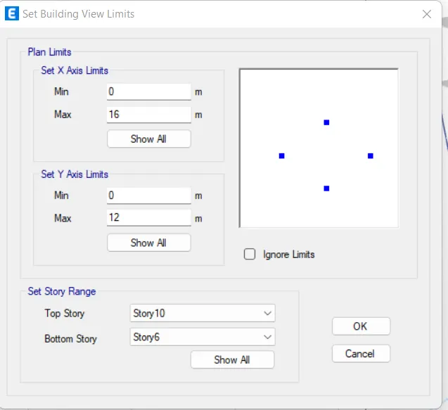
14. Now again select all slabs and provide Diaphragm property to the slab.
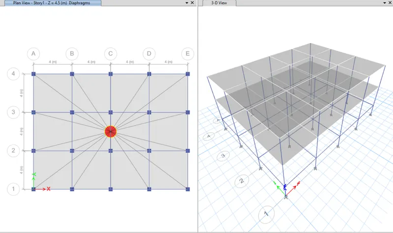
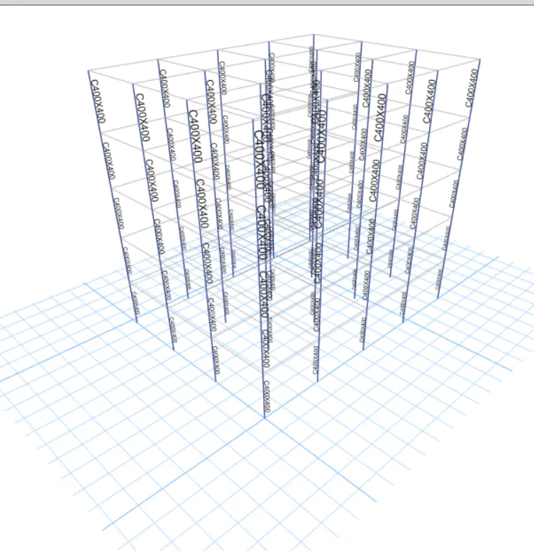
15. Now Run an analysis of modelling.
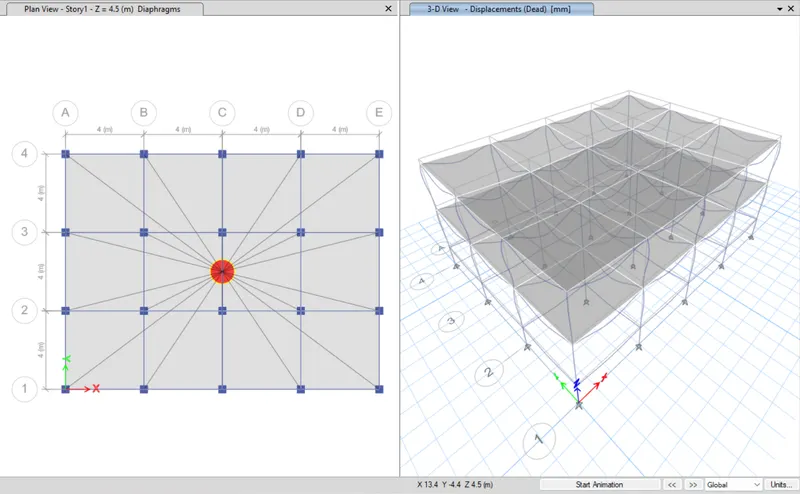
16. Now it saves as model b and proceeds to the next procedure.
BUILDING-B:(BENCHMARK 5 STOREY BUILDING):
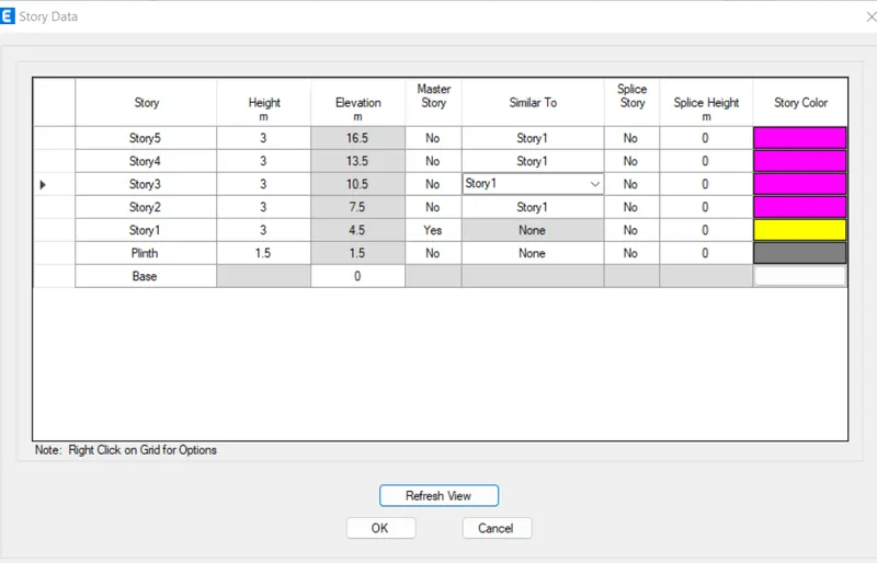
17. Go to the edit option to click on the edit story data, Now add 3 more storeys in the model B modelling.
18. Now check the loads with the help of show load patterns.
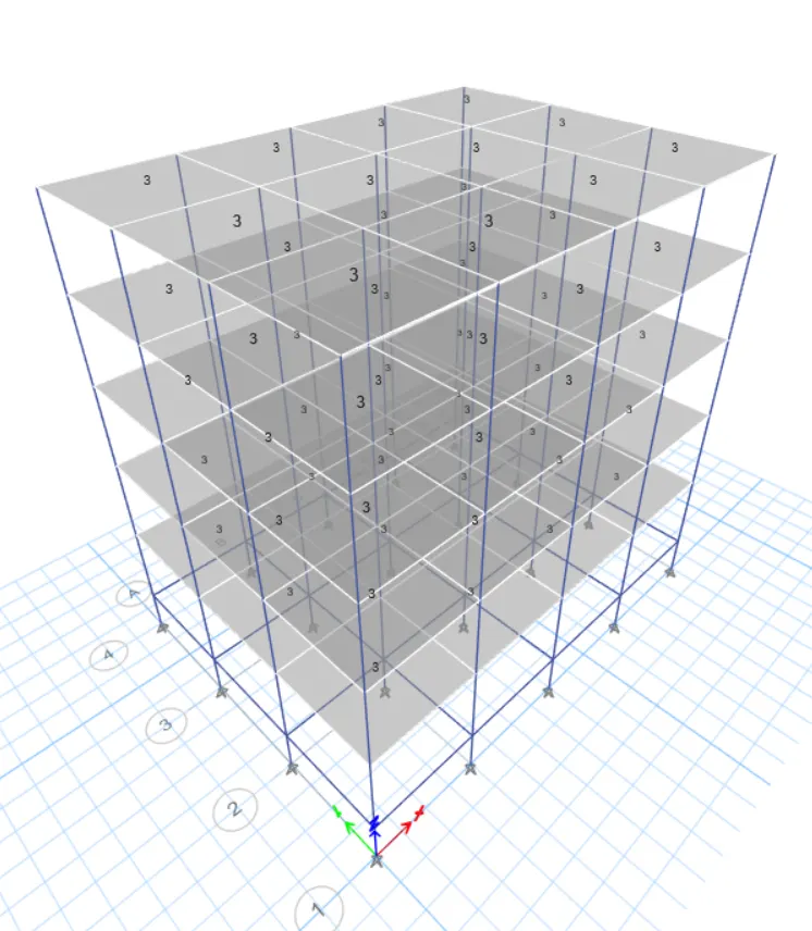
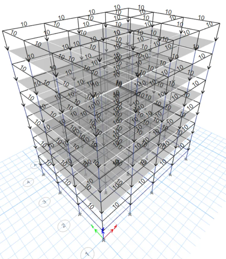
19. Now once Assign the diaphragm to the slab.
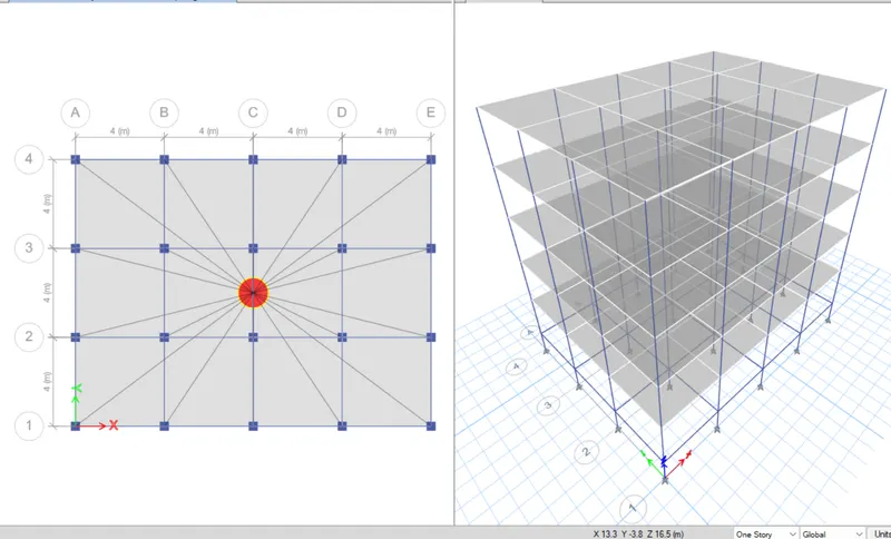
20. Now Run an analysis of the modelling.
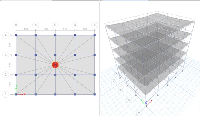
BUILDING-C:(BENCHMARK BUILDING WITH RECTANGULAR COLUMNS ORIENTED ALONG X-DIRECTION):
21. Now Model B saves it as Model C with a different column size.
22. Go to Define section, section properties and frame sections to select the column size to edit this column with C550x300 respectively.
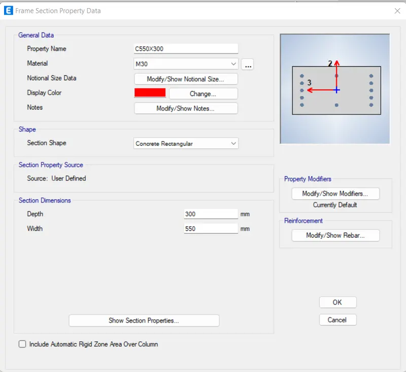
23. Now we have to orient the column in the X direction choosing the properties of column sizes and assigning the frame to the local axes keeping it as a 90. Now all columns are rotated 90 degrees.
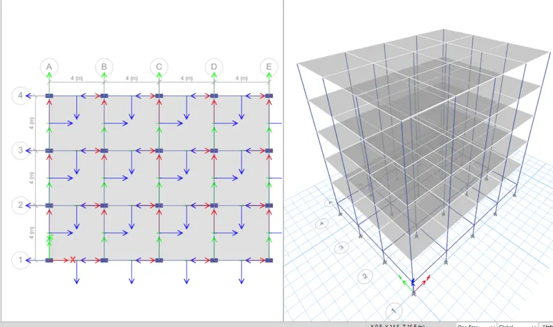
24. Now Assign the Diapharagm and run the analysis.
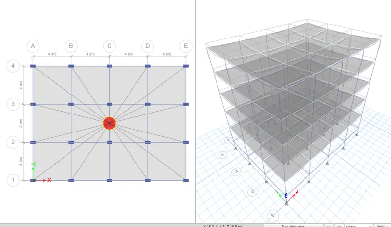
BUILDING-D:(BENCHMARK BUILDING WITH RECTANGULAR COLUMNS ORIENTED ALONG Y-DIRECTION):
25. Now Model C saves it as Model D.
26. Now we have to change only the X direction to the Y direction.
27. Go to select options and select the columns and assign the frame sections to local axes 90 degrees changes to 0 degrees, the columns are rotated about Y direction.
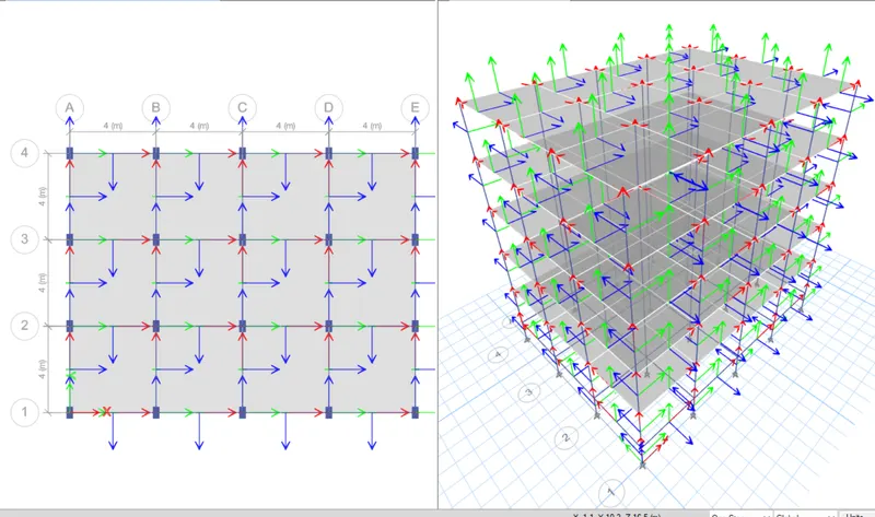
28. Now Assign the Diapharagm and run the analysis.
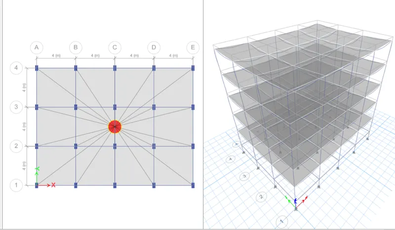
BUILDING-E:10 STOREY BUILDING WITH VARYING COLUMN SIZES ALONG WITH BUILDING HEIGHT:
29. Now Model D saves it as Model E.
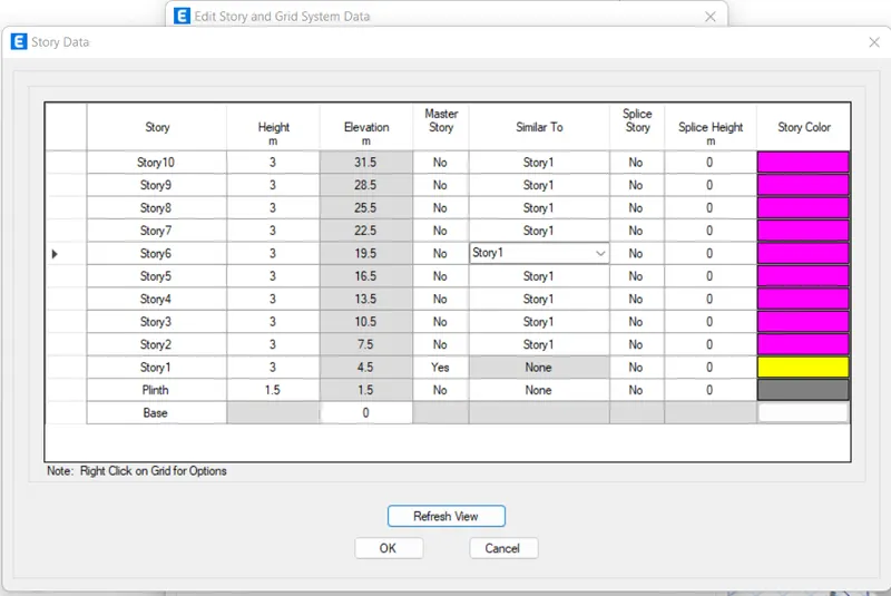
30. Go to the edit option to click on the edit story data, Now add 5 more storeys in the model E modelling.
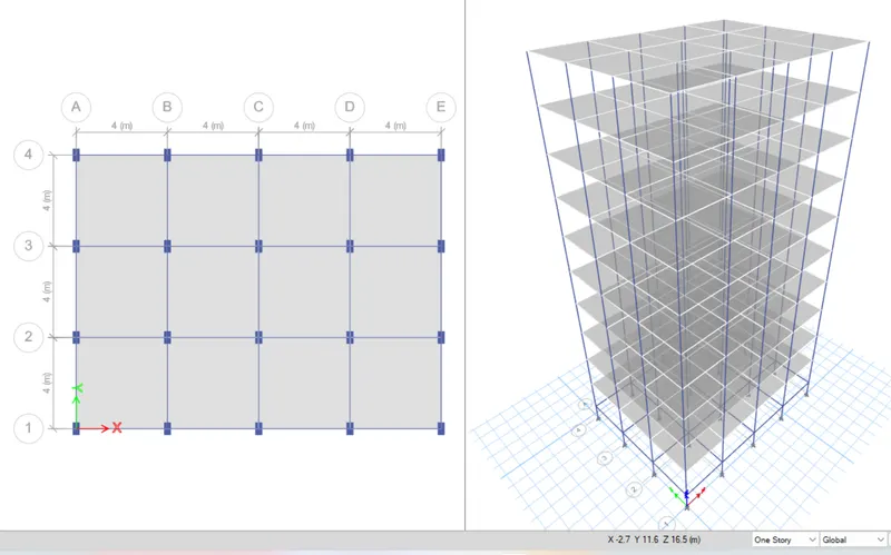
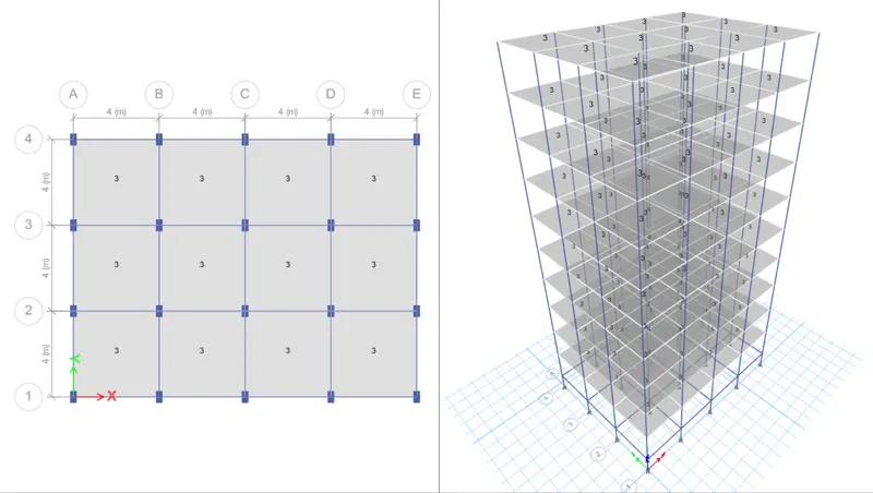
31. Now check the floor loads to the wall loads.
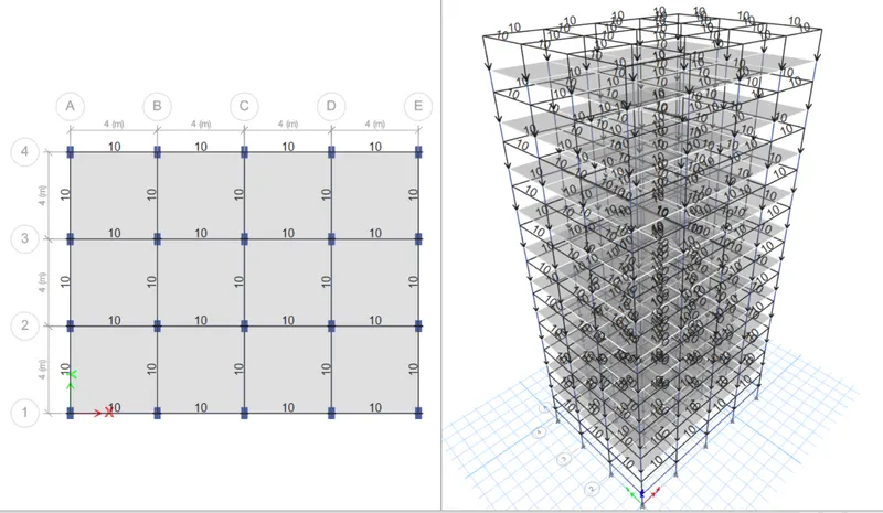
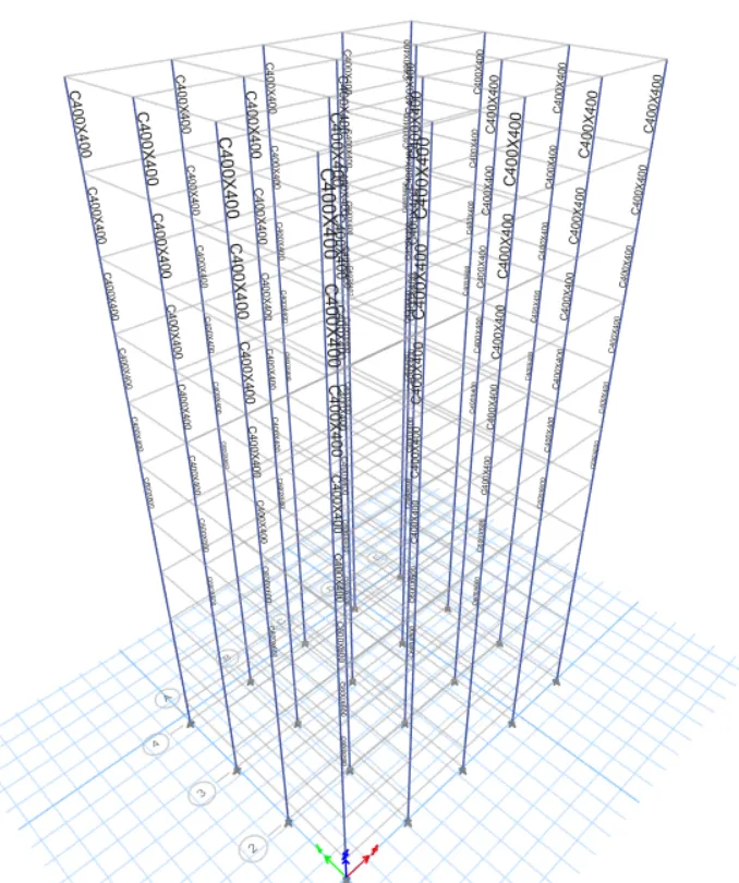
32. Go to Define section, section properties and frame sections to select the column size to edit this column with C600x600 and also create a new column property C 400X400 respectively.
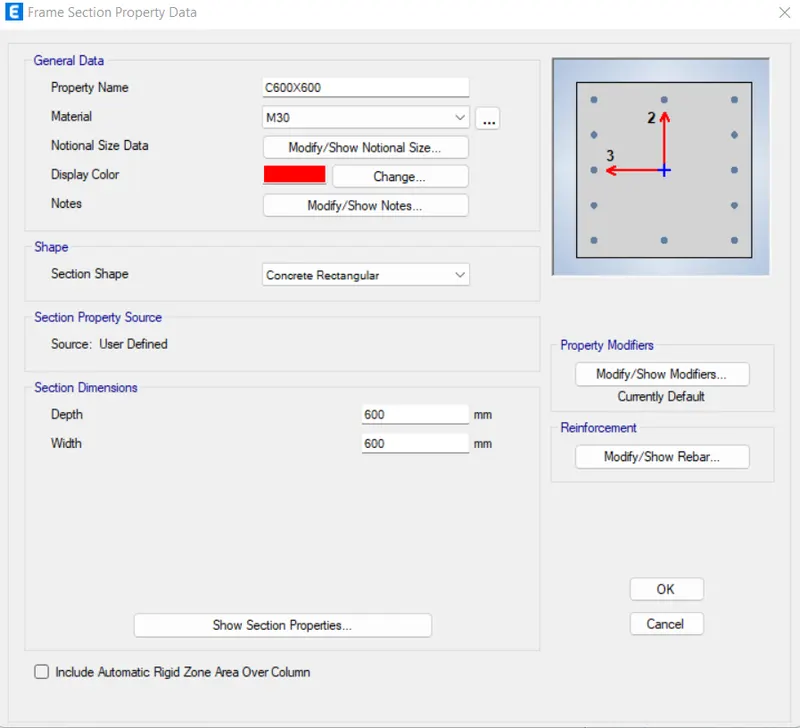
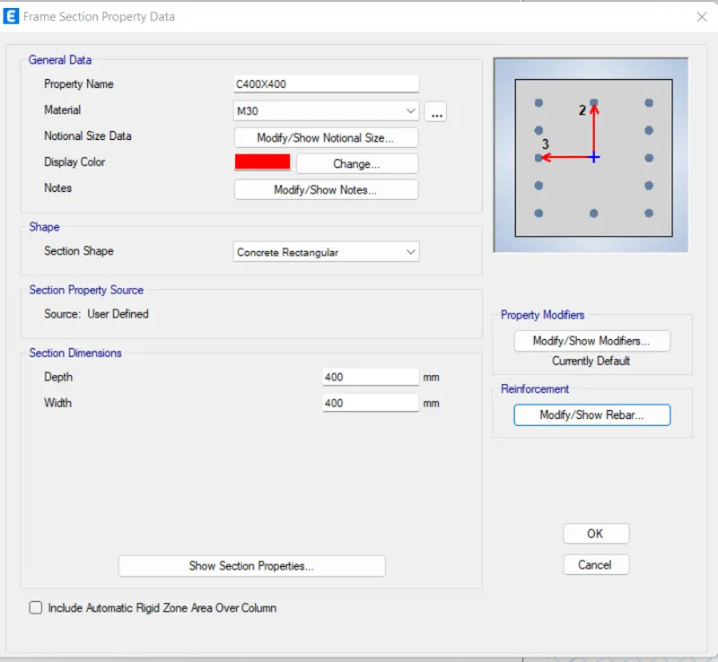
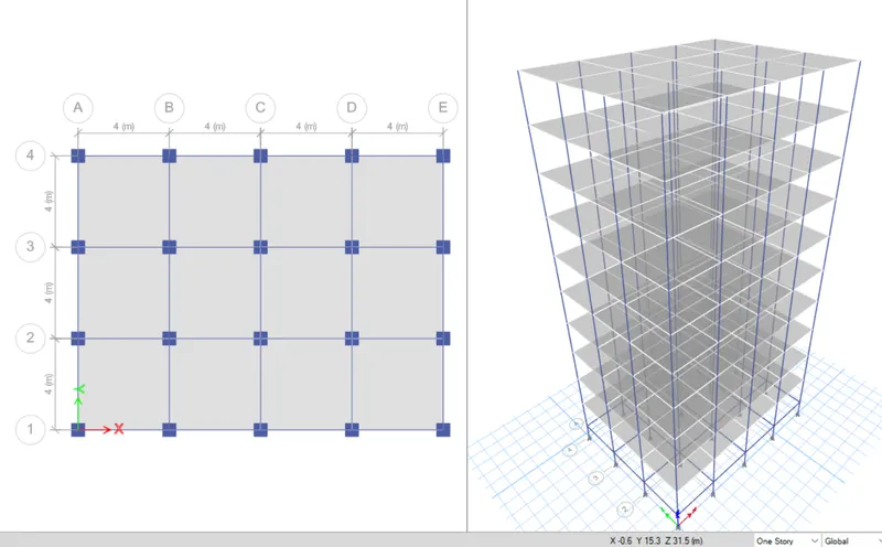
33. Now created two different types of column sizes and now assign the sizes top five storeys. Firstly Hide the beam and Floors now only visible to the columns.
34. After that I have to choose only storey number 6 to storey number 10.
35. Now Select all columns and assign the column sizes C400x400 top 6 to 10 floors respectively.
36. Now the bottom floors have sizes 600x600 and the top floors have column sizes 400x400 respectively.
37. Now Unhide all beams and floors to visible in the floor plan.
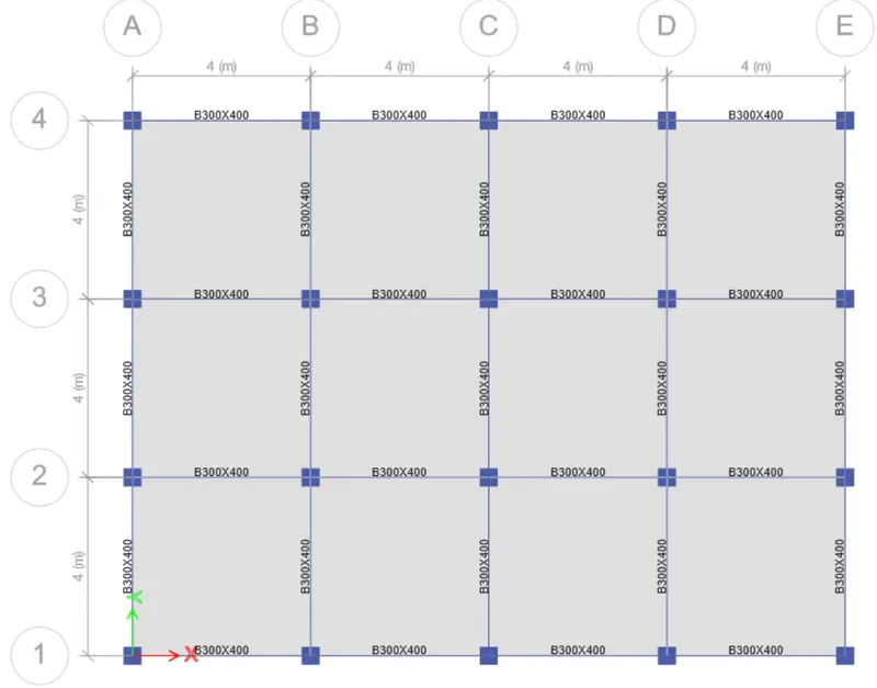
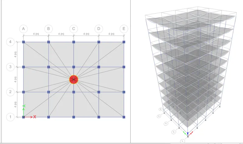
38. Now select the slabs and assign the diaphragm to run the analysis.
BUILDING-F:10 STOREY BUILDING
39. Now Model E saves it as Model F.
40. After that in the 10-storey building all column sizes change to 600x600 respectively. Firstly hide the beam and floors and select to the columns and assign the column sizes to top 6 floors to 10 floors.
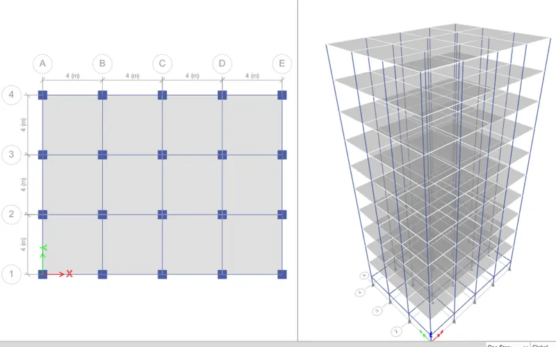
41.Now select the slabs and assign the diaphragm to run the analysis.
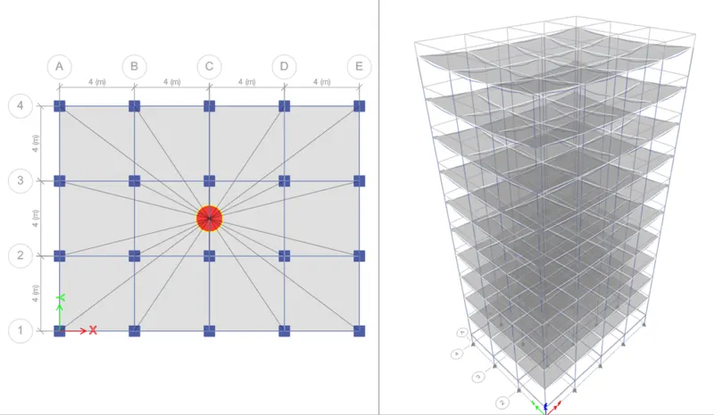
BUILDING-G:25 STOREY BUILDING WITH VARYING COLUMN SIZES ALONG WITH BUILDING HEIGHT:
42. Now Model F saves it as Model G.
43. Go to the edit option to click on the edit story data, Now add 15 more storeys in the model G modelling.
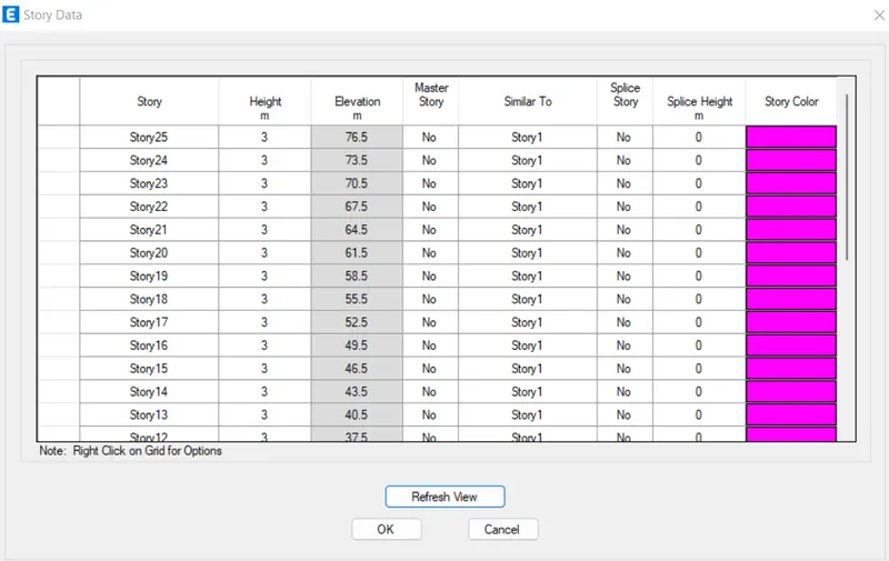
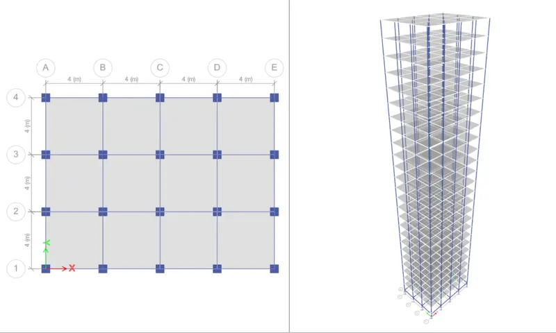
44. Now check the all live loads and wall loads.
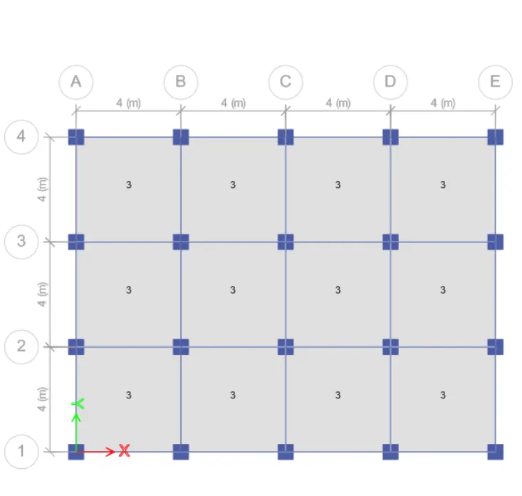
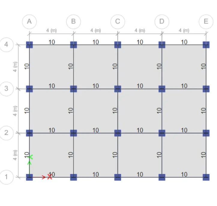
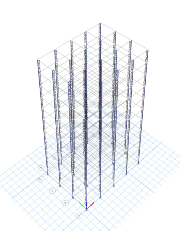
45. Now we have to define 3 column sizes C800X800, C600X600 and C400x400 respectively.
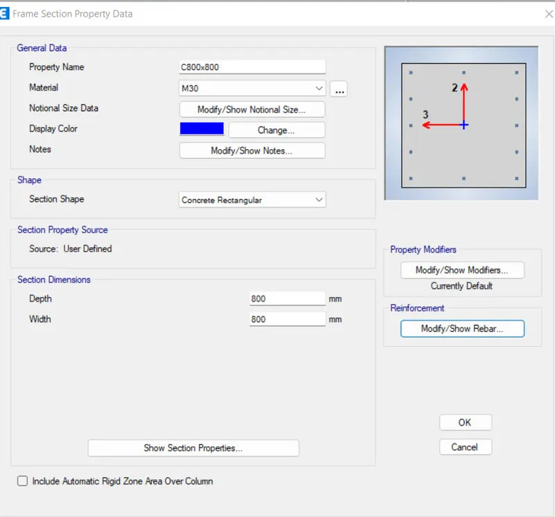
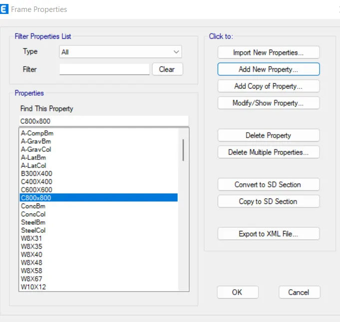
46. Now similar to the Model E building hide beams and floors and assign the column sizes to floors respectively.
Top 21 to 25 storeys: column size(400x400)
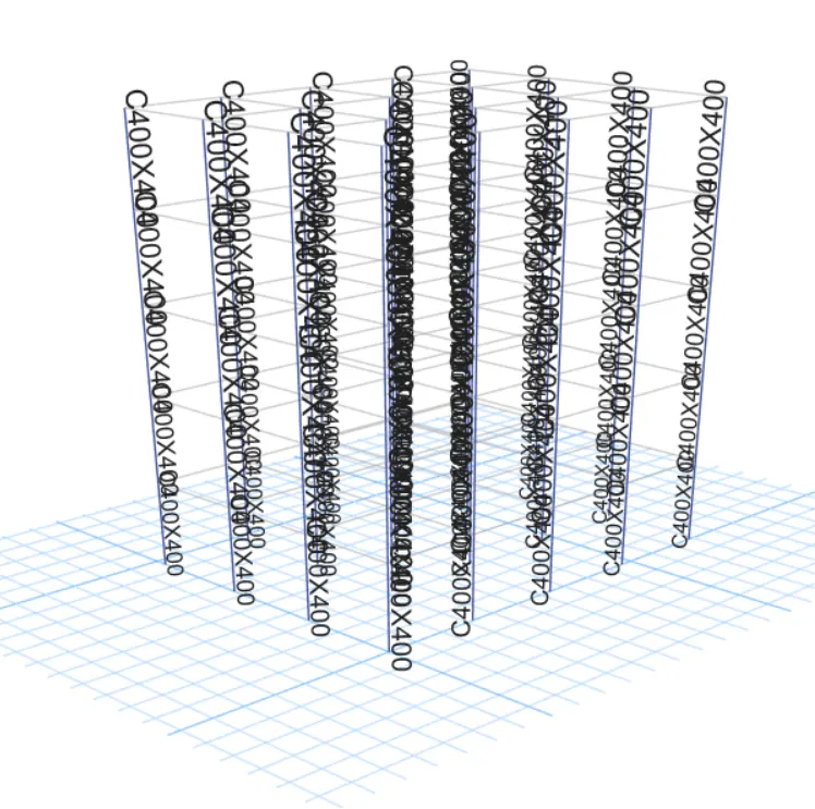
Top 11 to 20 storeys: column size(600x600)
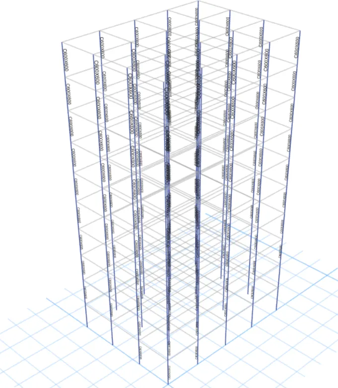
Bottom Base to 10 storeys: column size(800x800)
Extruded View:
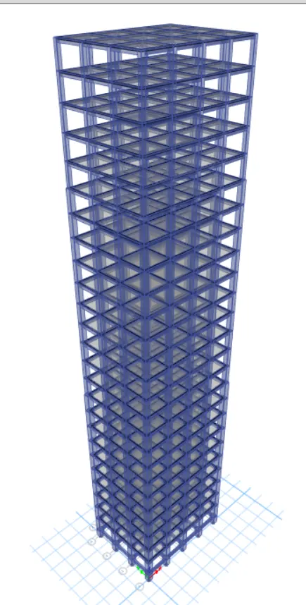
47. Now Select the unhide beam and floors to select the slabs and assign the diaphragm to run the analysis.
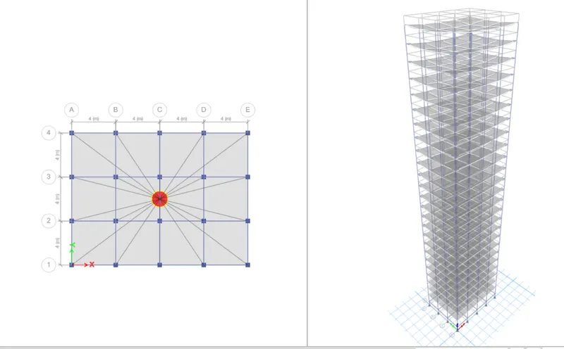
BUILDING-H:25 STOREY BUILDING:
48. Now Model G saves it as Model H.
49. Now all columns have a size is 800x800 mm. Similar to the above models hide the beam and floors and select columns and assign the sizes to 800x800.
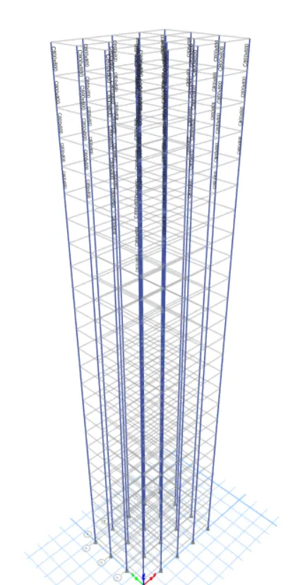
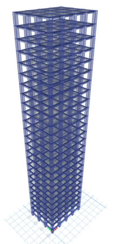
50. Now Select the unhide beam and floors to select the slabs and assign the diaphragm to run the analysis.
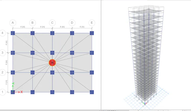
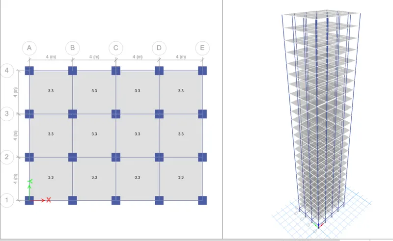
BUILDING-J:25 STOREY BUILDING WITH IMPOSED MASS 10% LARGER THAN THE BUILDING H:
51. Now Model H saves it as Model J.
52. After that select all slabs to assign shell loads uniform load 3.3 Kn/M2 and ensure the replace option and run analysis.
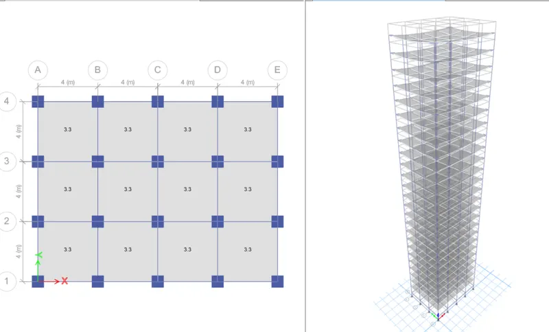
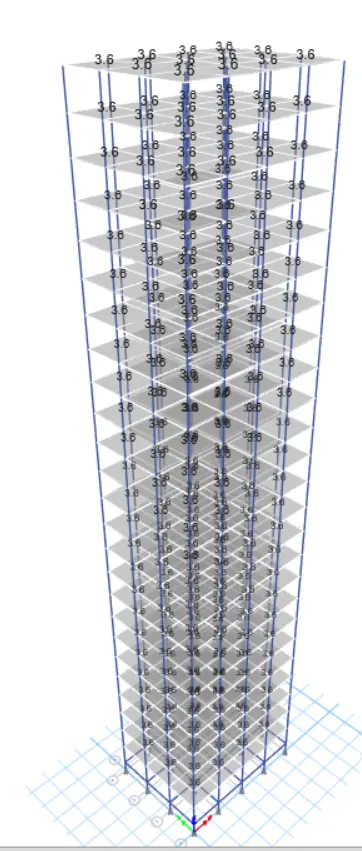
BUILDING-K:25 STOREY BUILDING WITH IMPOSED MASS 20% LARGER THAN THE BUILDING H:
53. Now Model J saves it as Model K.
54. After that select all slabs to assign shell loads uniform load 3.6 Kn/M2 and ensure the replace option and run analysis.
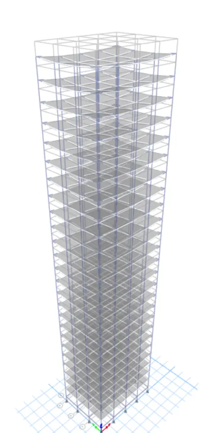
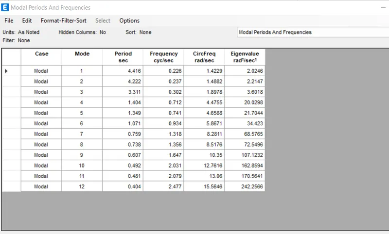
Effect of stiffness on T: Compare fundamental natural periods of buildings E & F as well as G & H. Why is there a marginal or significant difference in the fundamental natural periods?
Buildings E:
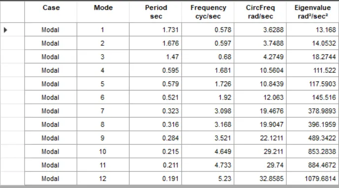
Buildings F:
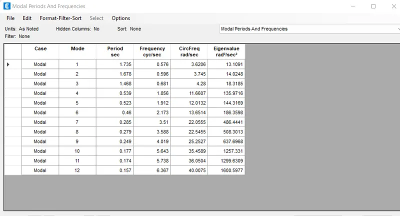
Buildings G:
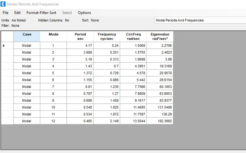
Buildings H:
| CRITERIA | MODEL | ANALYSIS RESULT | CONCLUSION |
| Effect of stiffness on Time period
|
Building E (10Storey with varying column size) |
1.73 s | For buildings E and F, varying column design doesn't make a big difference as there are only five stories. However, we can see that for buildings G and H, the consistent column size throughout the structure causes a more natural period. Therefore, it can be concluded that providing larger columns at the base and then reducing the size on top floors helps control the natural period 'T' for High rise buildings. |
|
Building F (10Storey with Uniform column size) |
1.73 | ||
|
Building G (25 Storey with varying column size) |
4.17 s | ||
|
Building H 25 Storey with Uniform column size) |
4.41 s |
Buildings J:
Buildings K:
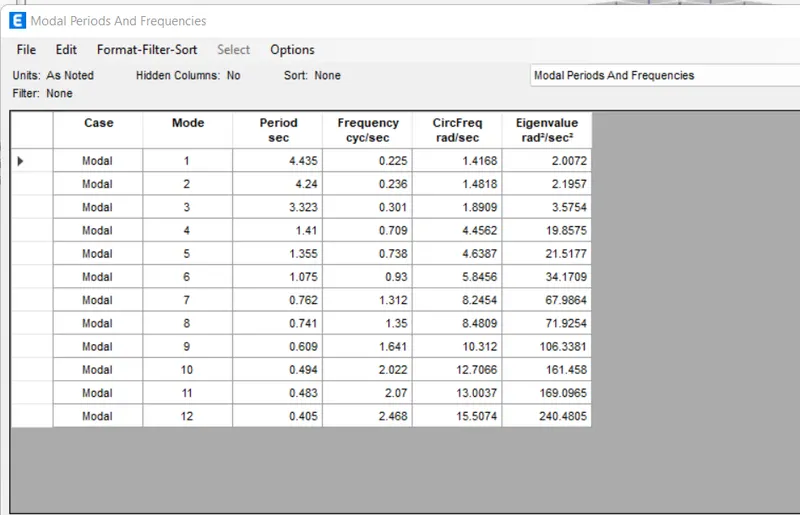
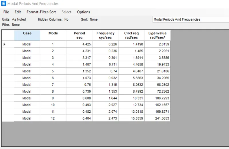
Effect of mass on T: Compare fundamental natural periods of buildings H, J and K. Have the buildings become more flexible or stiff due to change in mass?
| CRITERIA | MODEL | ANALYSIS RESULT | CONCLUSION |
| Effect of mass on T |
Building H 25 Storey with 3 KN/m2 imposed load) |
4.41 s | Look at these values, the natural period for Highrise buildings is directly proportional to the imposed mass of the building . |
|
Building J 25 Storey with 3.3 KN/m2 imposed load) |
4.42 s | ||
|
Building K 25 Storey with 3.6 KN/m2 imposed load) |
4.43 s | ||
Effect of Building Height on T: How do the fundamental natural periods of Buildings A, B, F and H change with a change in building height?
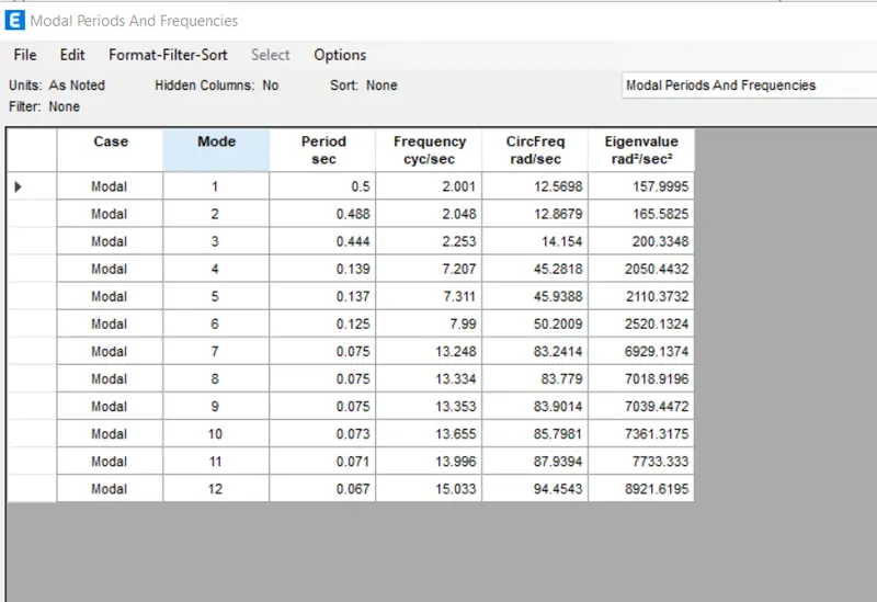
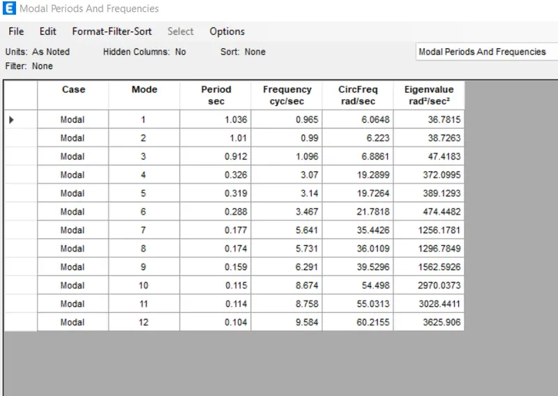
| CRITERIA | MODEL | ANALYSIS RESULT | CONCLUSION |
| Effect of Building Height on T |
Building A (2 Storey) |
0.5 s | Look at these values, the natural period 'T' is also directly proportional to the building height. |
|
Building B (5 Storey) |
1.03 s | ||
|
Building F (10 Storey) |
1.7 s | ||
|
Building H (25 Storey) |
4.41 s |
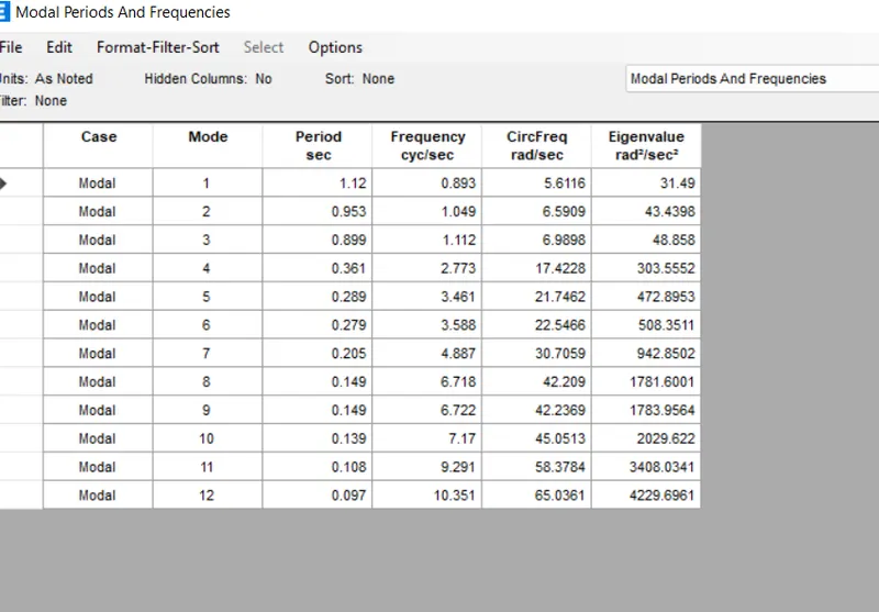
Effect of Column Orientation on T: How does the fundamental natural periods of Buildings B, C and D change with change in column orientation?
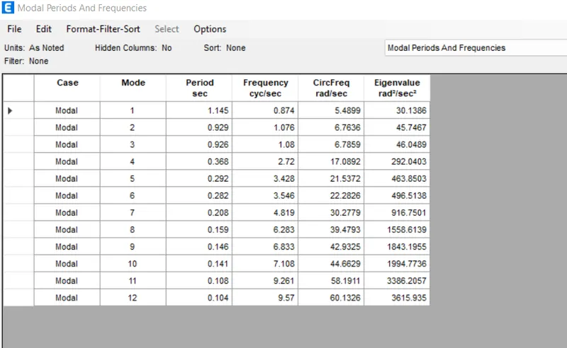
| CRITERIA | MODEL | ANALYSIS RESULT | CONCLUSION |
| Effect of Column Orientation on T |
Building B (All floor column sizes 400x400) |
1.03 s | When the column cross-section is square 400x400, there is no difference between the lateral displacement in both the orthogonal directions. However, when you orient the column in a particular direction be it X or Y, the lateral displacement in that particular direction will be less than that in the other direction which has a lesser column length. |
|
Building C (All floor column sizes 550x300 oriented in X direction) |
1.14 s | ||
|
Building D (All floor column sizes 550x300 oriented in Y direction) |
1.12 s |
Effect of Flexural stiffness of structural elements on mode shapes :
- Now open to model B and save it as a Model B zero.
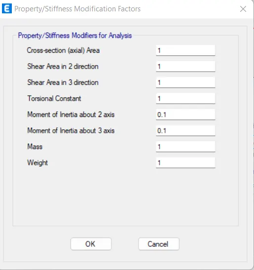
- After that define a beam property,go to modify the property to change it to a moment of inertia about axis 0.1 and 0.1 respectively. Finally run analysis.
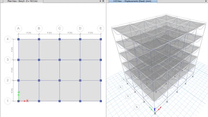
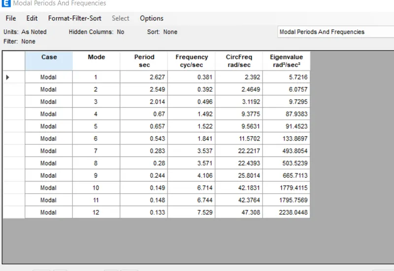
| CRITERIA | MODEL | CASE | ANALYSIS RESULT | CONCLUSION |
| Effect of Flexural stiffness of structural elements on mode shapes |
Building B |
Flexural stiffness of beams close to nil(Zero inertia) |
2.63 s | If you decrease the flexural stiffness of beams, the overall flexural strength of the beam is reduced, and consequently, the fundamental natural period is twice the flexural stiffness beams close to zero. |
| Full flexural stiffness of beams (Regular) | 1.03 s |
Effect of Axial stiffness of structural elements on mode shapes:
- Now open to model H and save it as a Model H zero.
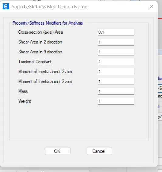
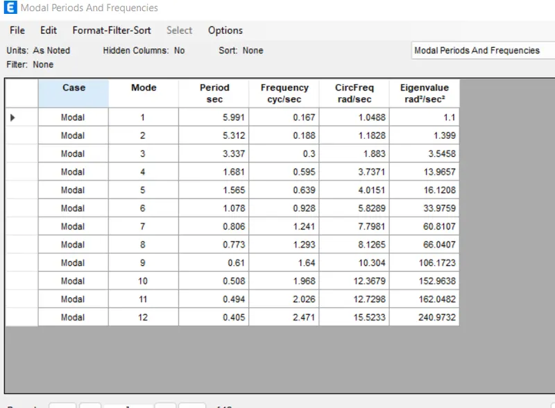
- After that define a Colum property, go to modify the property to change it to an axial area 10%, Finally, run an analysis.
| CRITERIA | MODEL | CASE | ANALYSIS RESULT | CONCLUSION |
| Effect of Axial stiffness of structural elements on mode shapes |
Building H |
Axial cross section for columns close to nil(Zero inertia) |
5.99 s | As the axial stiffness of columns decreases, the fundamental natural period of the building increases. |
| Full axial stiffness of columns (Regular) | 4.41 s |
Effect of Degree of fixity at column base on mode shapes :
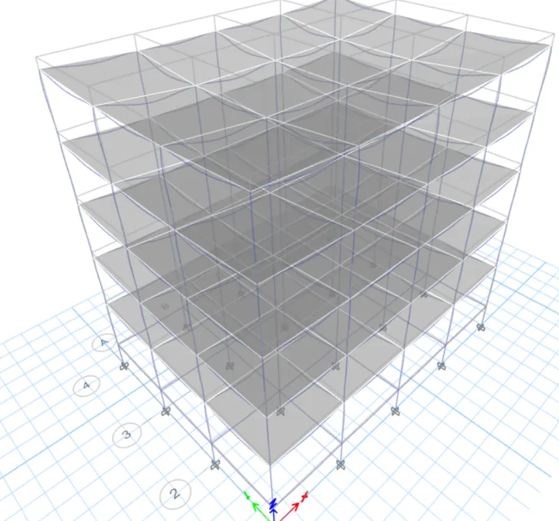
- Open model B building.
- Now change the supports pinned to fixed. Go to elevation View.
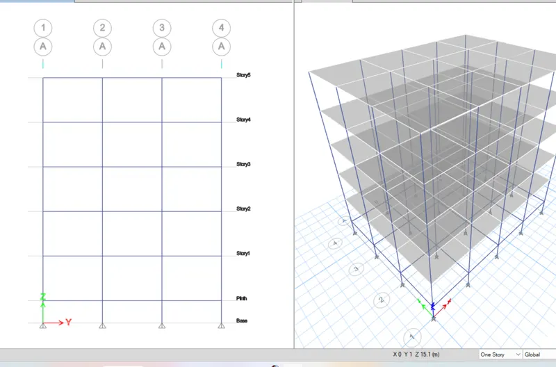
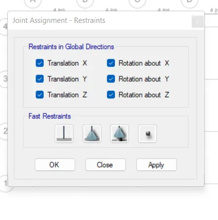
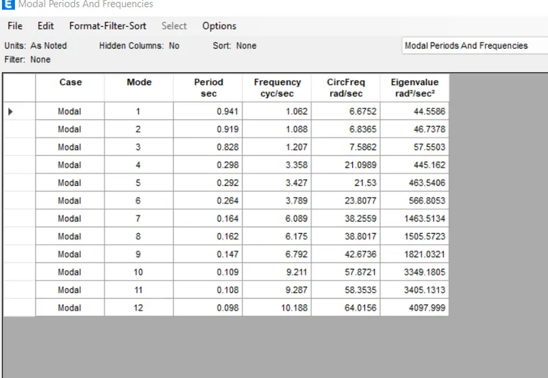
- Now go to plan view to select base and select all joints .then select joints to restrain then choose the fixed option. Finally, run an analysis.
| CRITERIA | MODEL | CASE | ANALYSIS RESULT | CONCLUSION |
| Effect of Degree of fixity at column base on mode shapes |
Building B |
Column support pinned(regular) |
1.03 s | The pinned support restraints are compared to the fixed one which leads to more movement and thus increased natural period. As a result, it can be concluded that the fixed support will give you better control over the fundamental natural period of buildings. |
| Column support fixed | 0.941 s |
. ....................................................... THE END......................................................................................................................