Project 1_Comparative study of different storey buildings for Seismic forces
Project
Comparative study of different storey buildings for Seismic forces
Factors influencing the dynamic characteristics of a building
Factors influencing the dynamic characteristics of a building
Factors influencing the Mode shape of oscillations
AIM :
To compare the different storey building for seismic forces
Given elements :
Structural Element Sizes
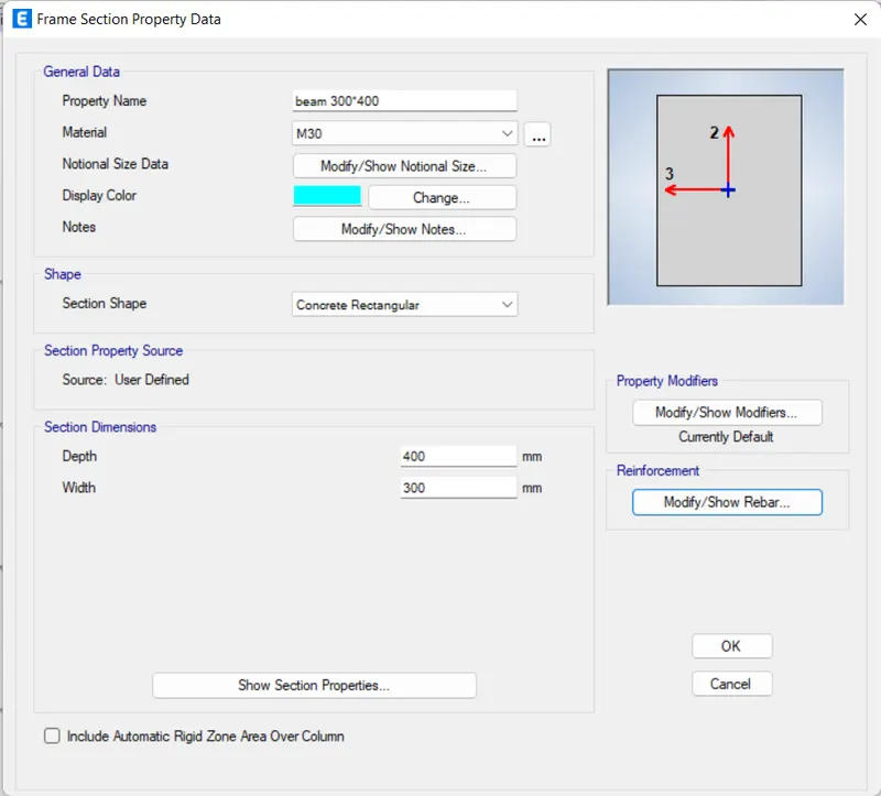
- Beams : 300 × 400 mm
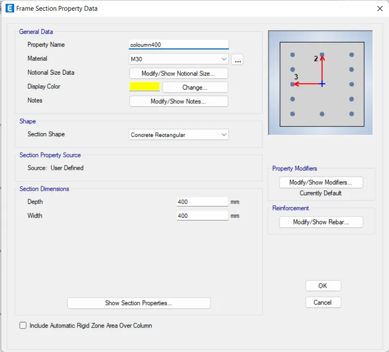
- Columns : 400 × 400 mm
- Slab : 150 mm thick
Material Properties
- Grade of Concrete : M30
- Grade of Steel Reinforcement Bars : Fe 415
Loading
- Dead Load on beams from infill wall : 10 kN/m
- Live load on floor : 3 kN/m2
Buildings are assumed to be pinned at base
Five-storey Benchmark Building: Elevation and plan of benchmark building showing the structural moment frame grid (All dimensions are in mm)
Procedure :
Building "A":
- Open the ETABS software and the user interface will open

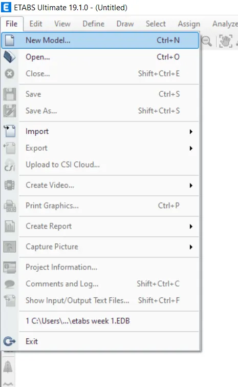
- Now click on the file tab and select the new model
- The model initialization window will pop up and secet the use built option
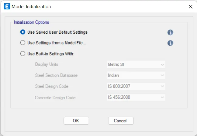
- After that chnage the units codes then click on ok
- Then the templates file will popup the emter the grid dimentions ans spacing number of storys as mentions in the quation
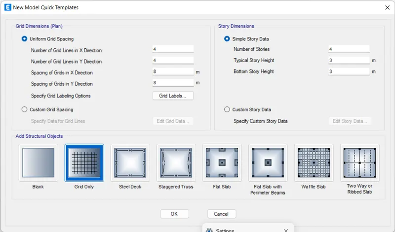
- Click on custom grid spacing then click on Edit grid data option then the grid system data window will popu
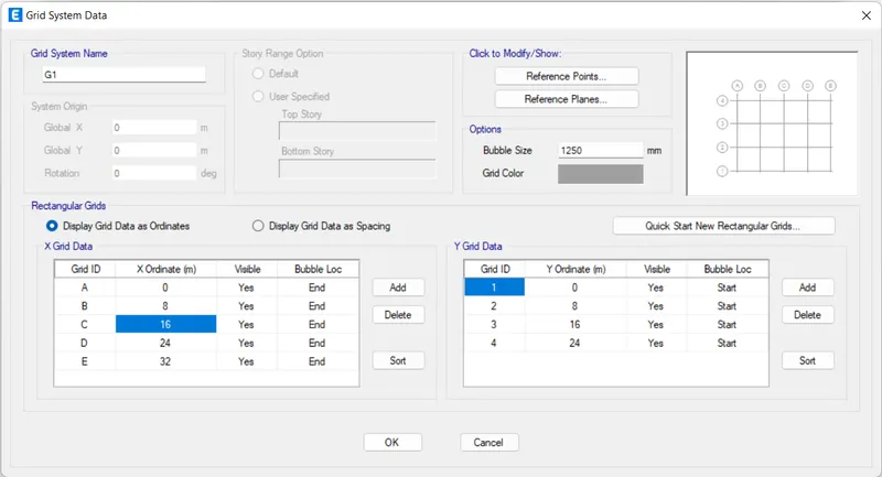
- In the qus we have 5grids in x direction spacting 4m ans 4grids in y direction 4m spacing
- Add grids and after providing data click on ok
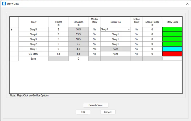
- Now in the story dimention click on the custom story data the window will popup then enter the details as per question
- first we have to change the dimention of plinth as 1.5m
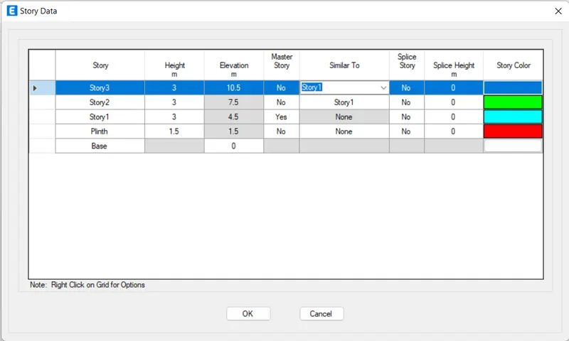
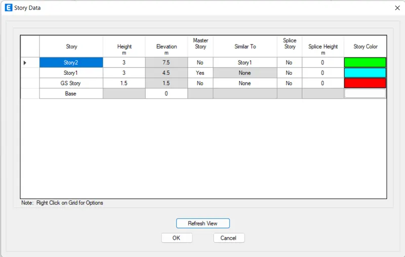
- And rename all and select master story as story1 and story 2
- delete the remaining storys
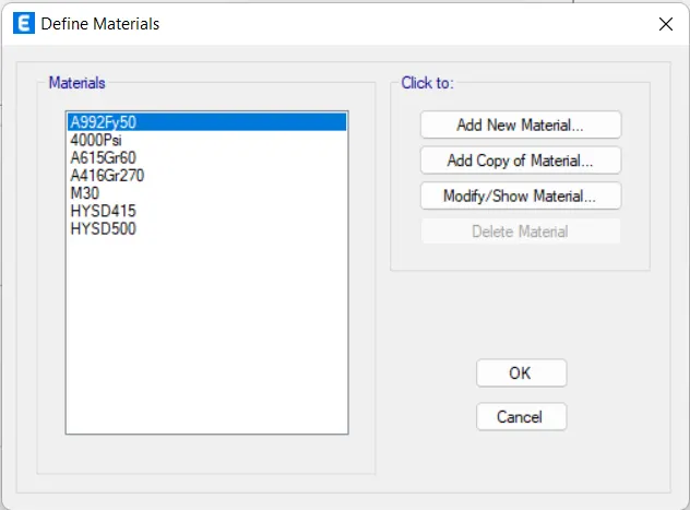
- Now go for define tab then select the metarial property then the window will popup and add meterial we use.

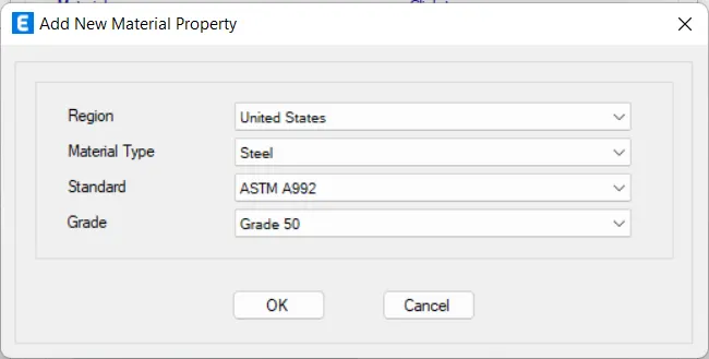
- first we have change the region to india and material and its standerds and grades
- we will use M30 concrete and fe415 and 500 steel we should provide the data as given below
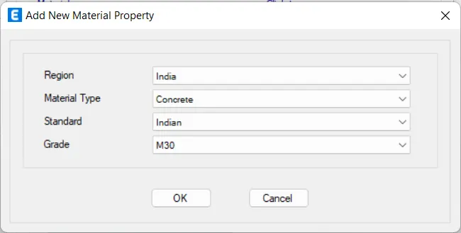
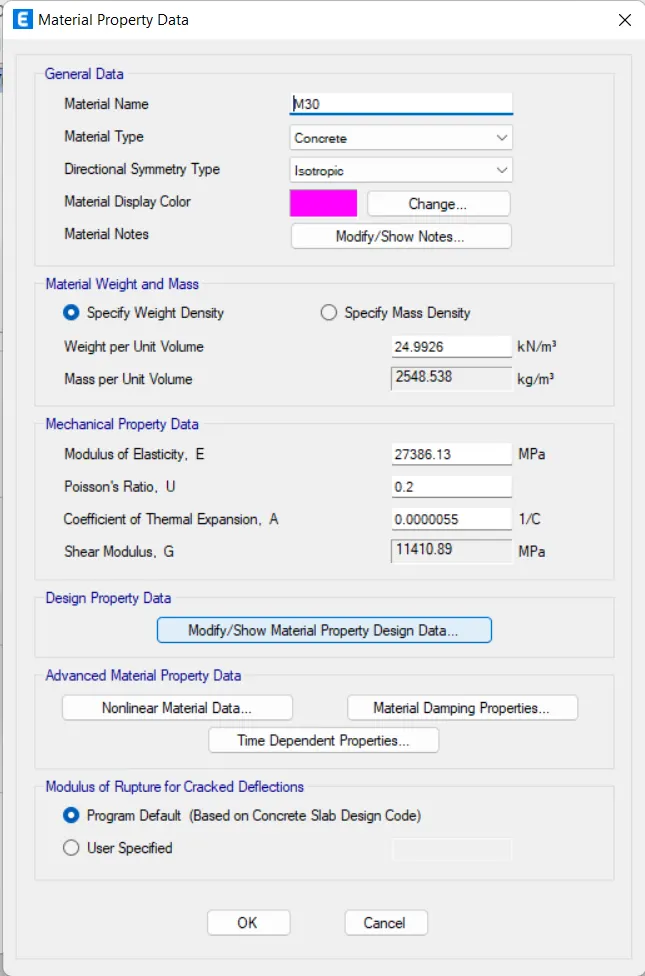
- This is for concrete
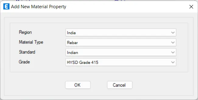
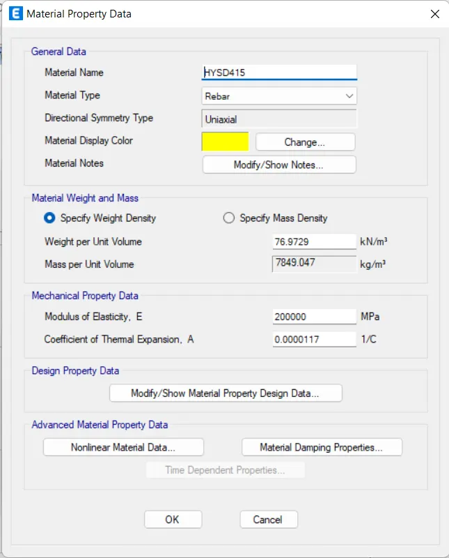
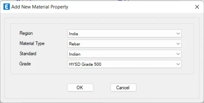
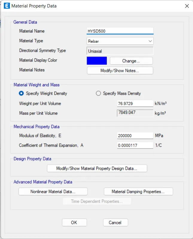
- This for rebars odf steel metarials
- After that click on ok
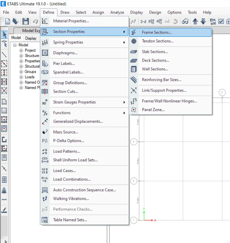
- Now in the define tab select the the section property then select the frame section and provide data
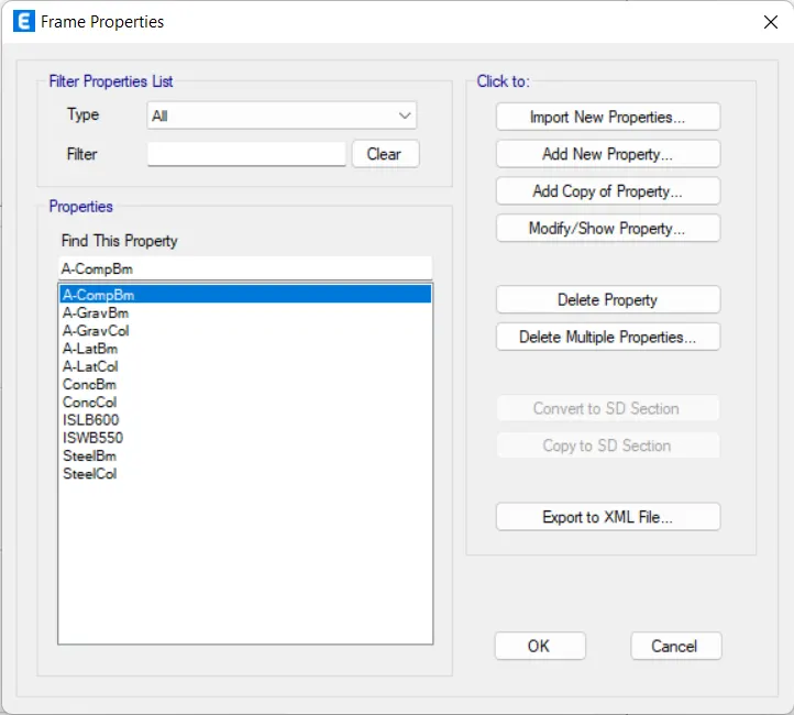
- Now click on the new property and the window will popup proivide data
- Beam data below
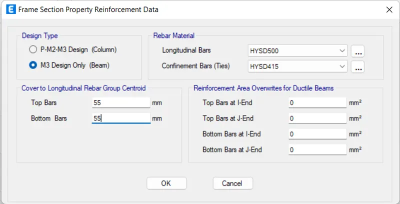
- Reinforcement data
- Coloumn data:
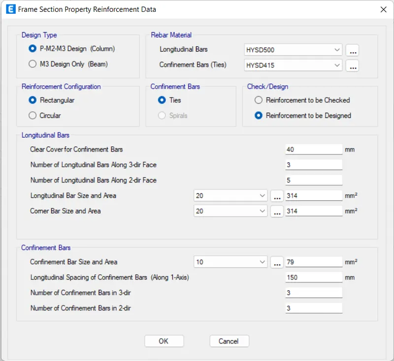
- Coloumn reinforcement
- In the same the go the tha slab sections
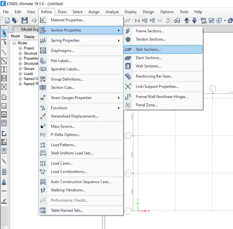
- Slab data:
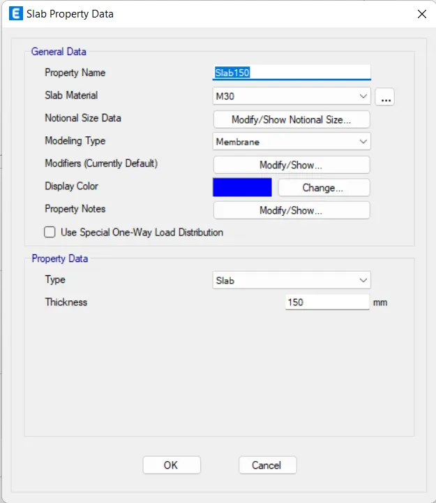
- Now go to the load patterns
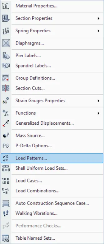
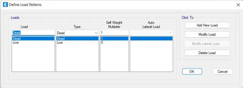
- Now define loads
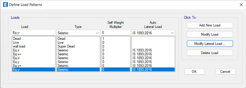
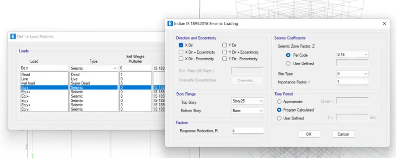
- MOdify the Lateral loads
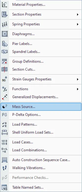
- In the define tab select the mass source..
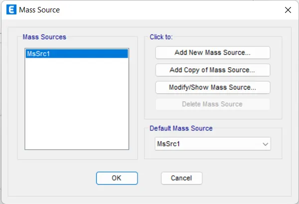
- Now click on the add copy of mass source..
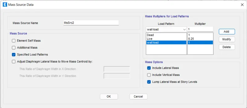
- Now select the specified load patterns then change the load multiplier then click on ok
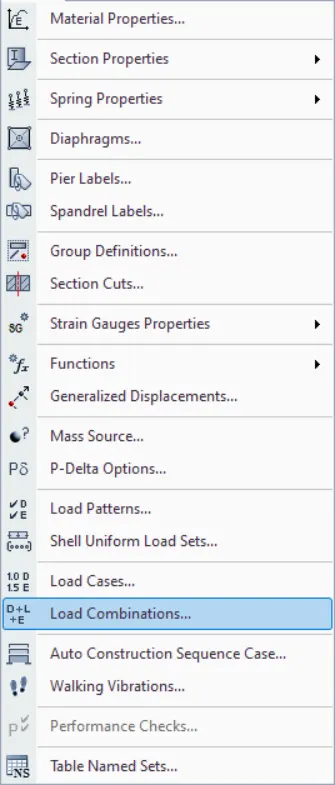
- NOw click on the load combination... the window will popup
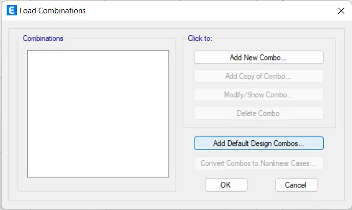
- select the add default option then select the concrete frame option
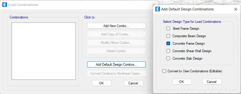
- The default combinations will be loaded
- Then click on ok
- Now the material defining stage completed
- It is modeling stage now click on the quick draw coloumn tool
- change the settings one story to all storys and draw the coloumns
- The columns will be drawn below
- And aslo draw beams and slabs by changing material
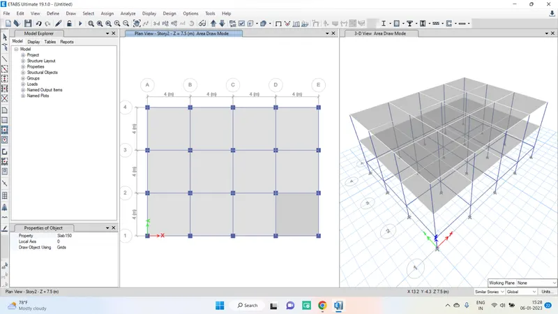
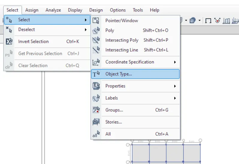
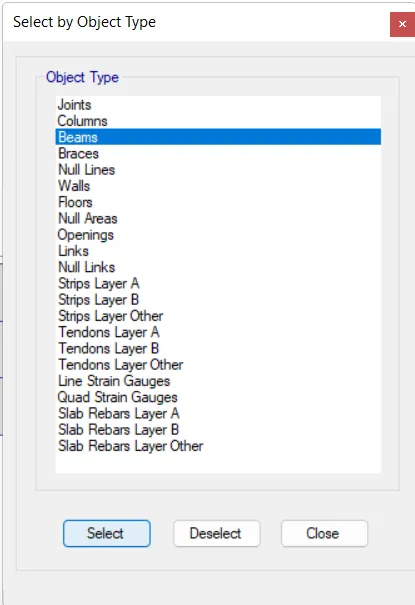
- Now by using select option select the beam elements
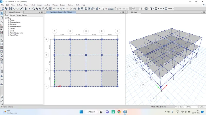
- Now go to assign tab select the frame loads and the select the udl
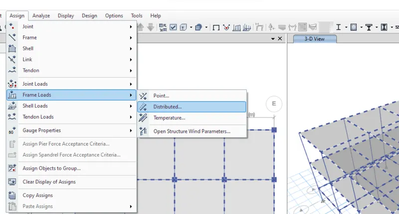
- The frame load window will popup
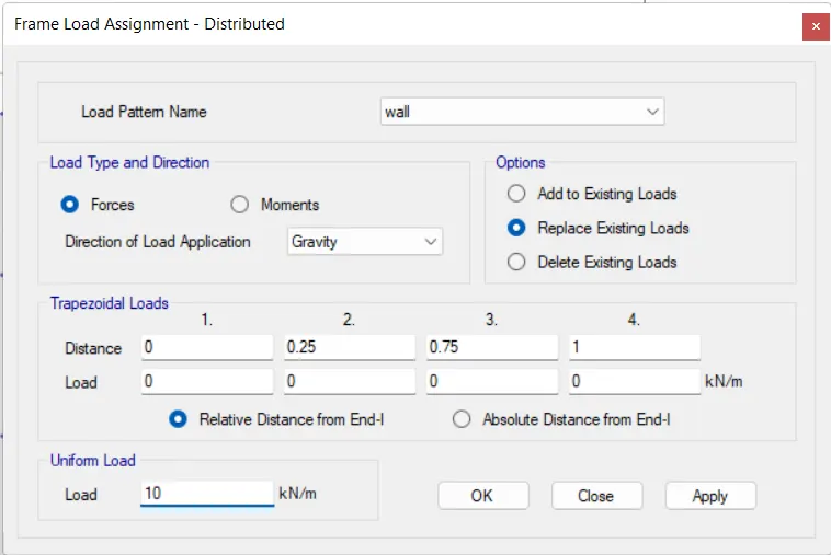
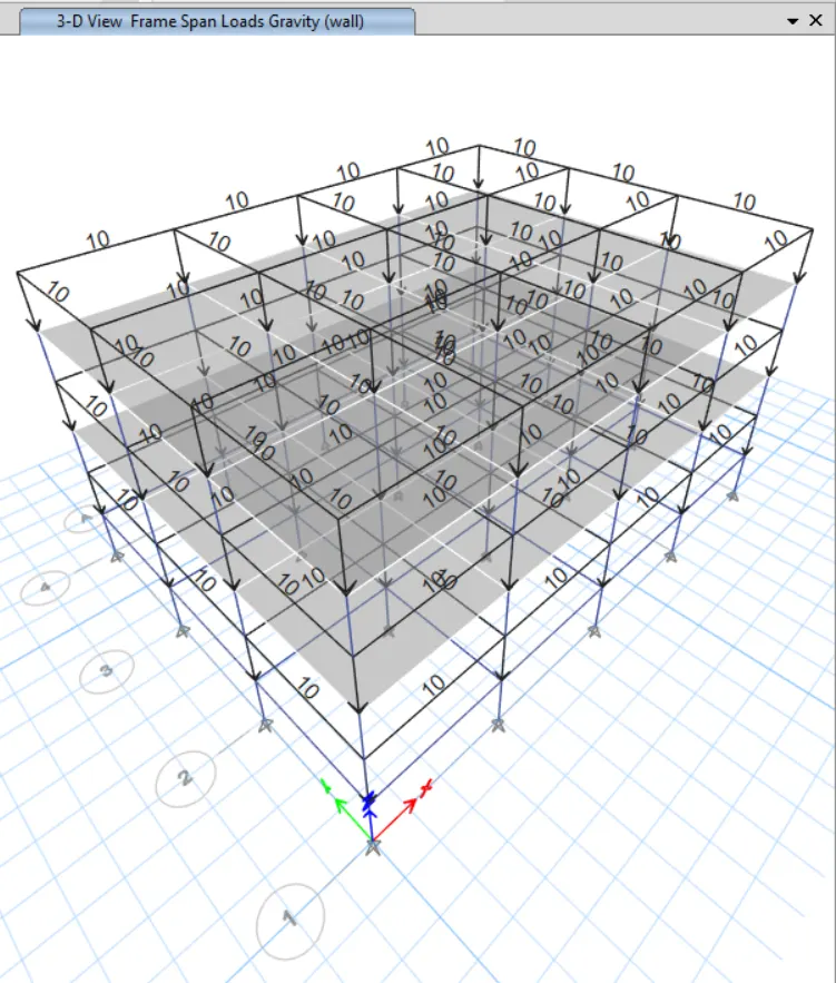
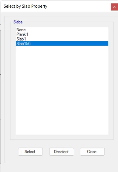
- Now by using the select option select the properties of slab the go to assign tab
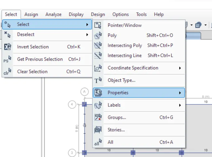
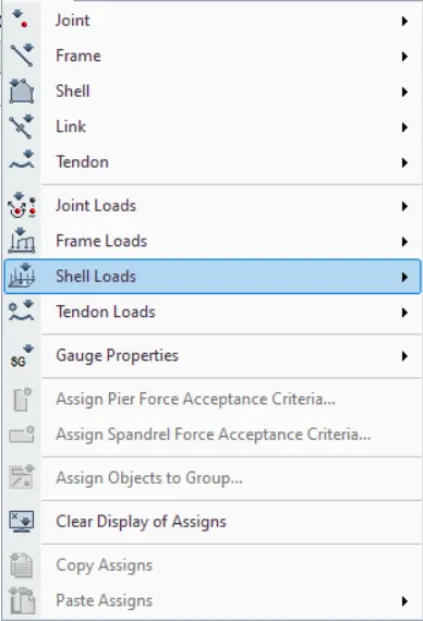
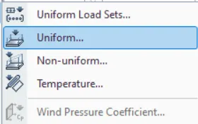
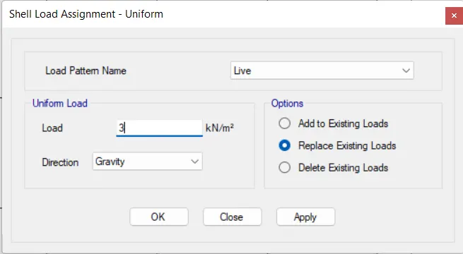
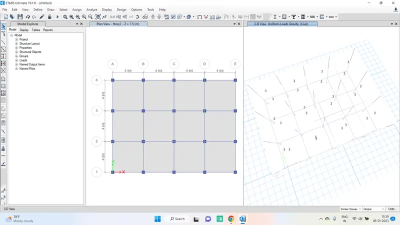
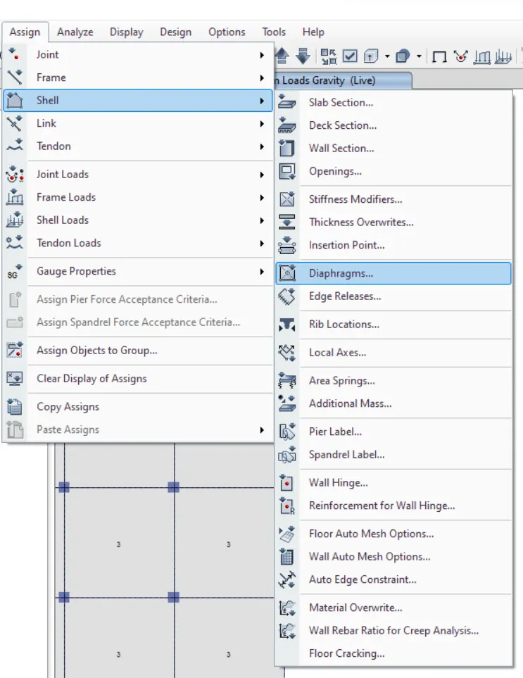
- Again select the slab property then go to the assign tab then select the shell option then diaphragms option the window will popup
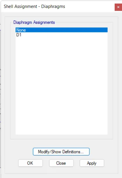
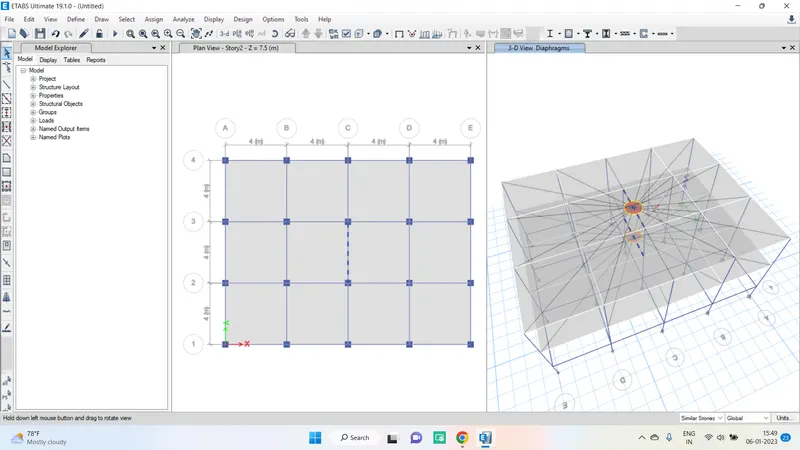
- Now save the file As building "A".
Building "B" :
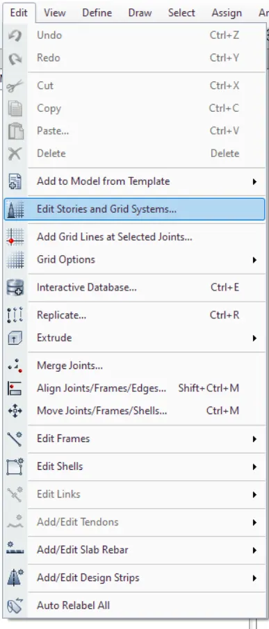
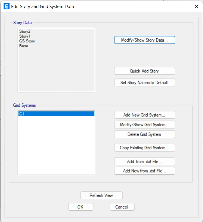
- After saving the A file then Click on Edit tab then select the edit grid option.Then the edit window will popup then click on the modify option and then add 3storys
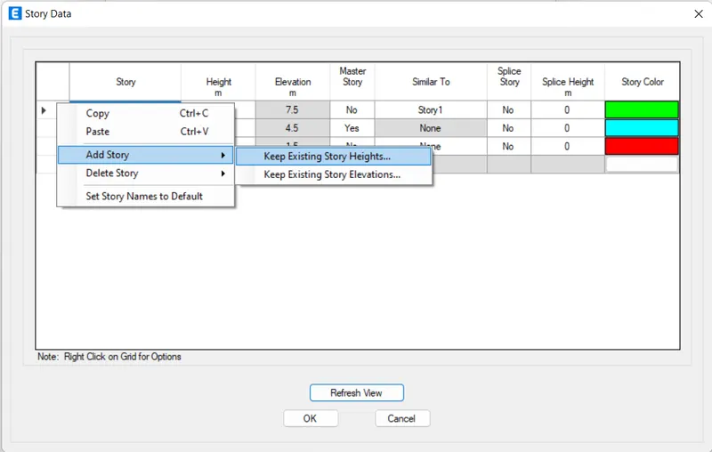
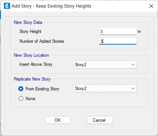
Now click on ok then change the similar story as story1 for above then cilck on refresh view after that the storys will updated.
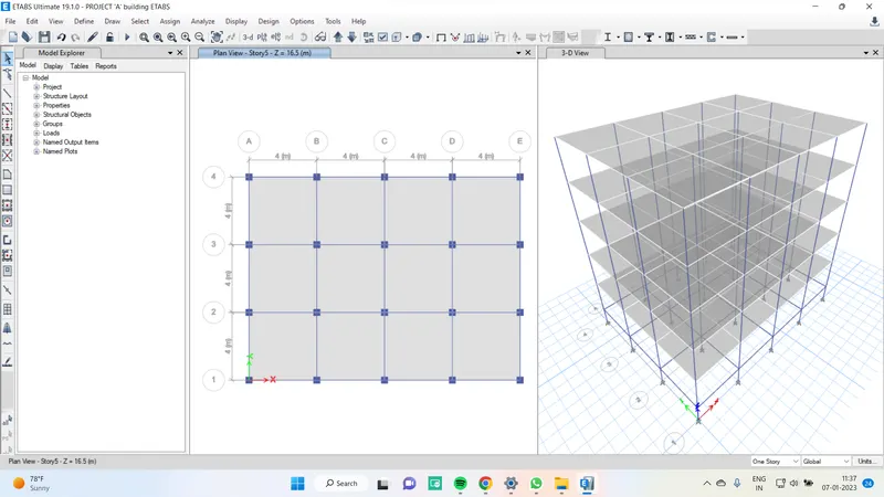
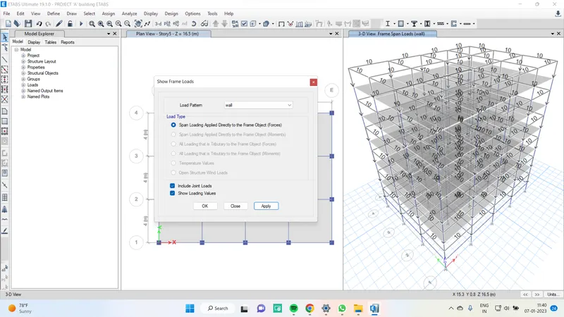
Now click on the dislay freame load in the display tab then assign to the view
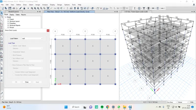
Same as the again select the display shell load option then select the live load rthen click on ok then it will diplayed as below
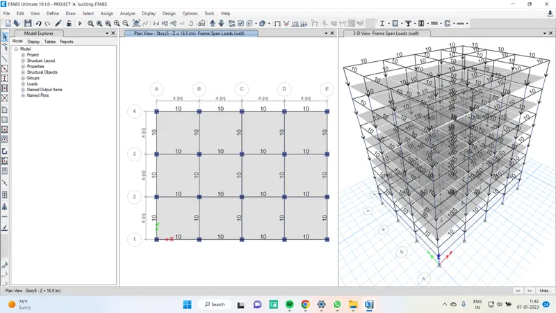
If we didnt applied the diaphgram then select the slab property then assign the diaphagram to the selected slab
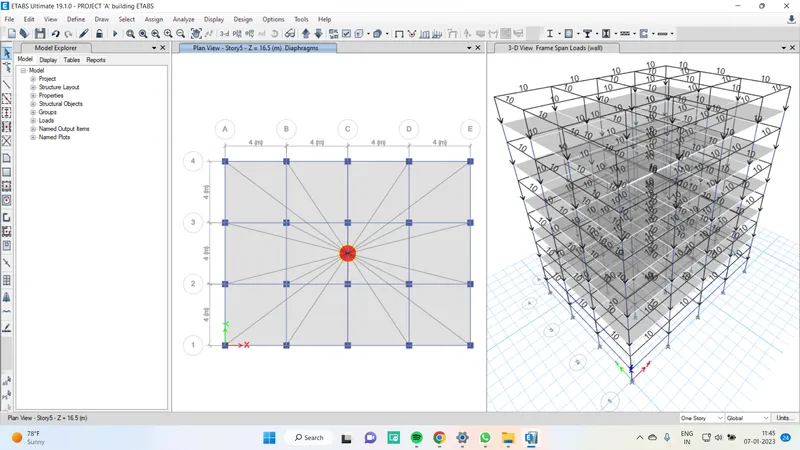
Now select the run analysis option then save it as Building " B "
Building "C" :
The Building C have same number of storys but the column sizes where different (550x300)
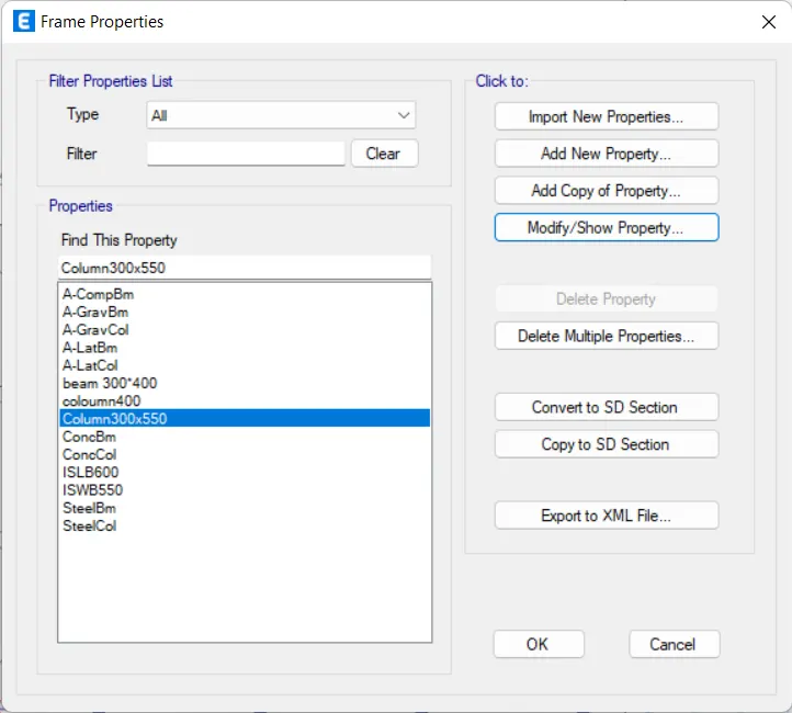
For that we have to go the define tab then section properties> Freame sections
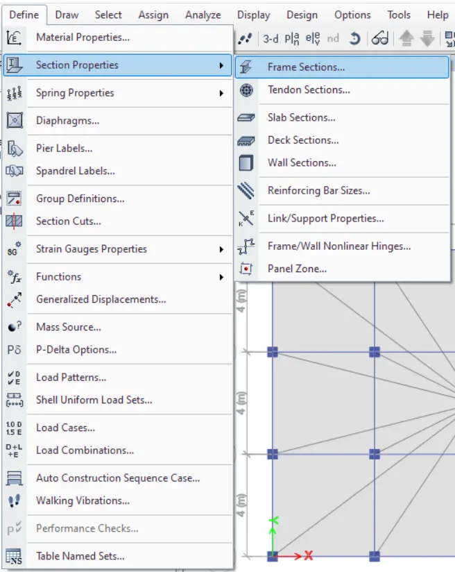
The Frame property window will popup then select the add new property option then select material and dimention of the column
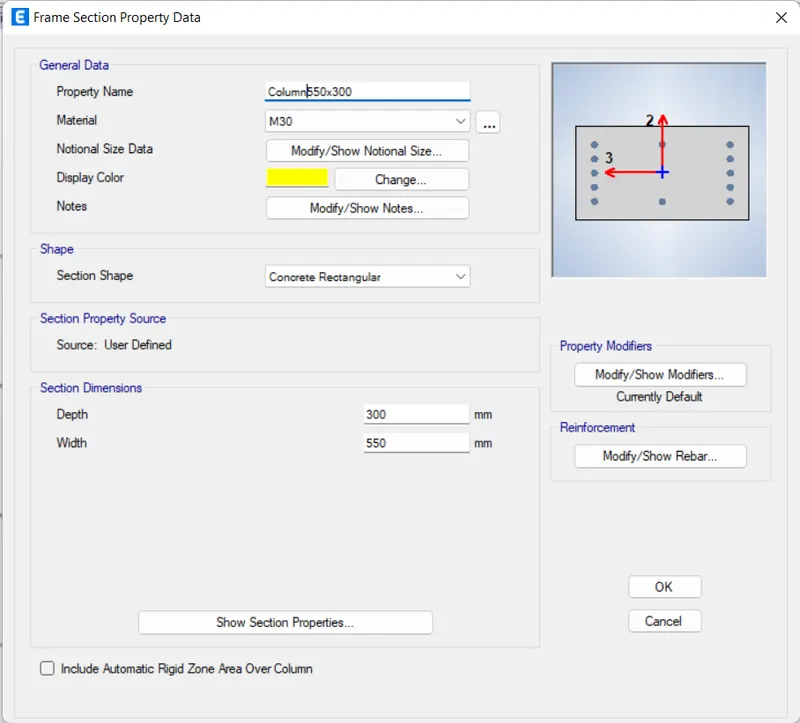
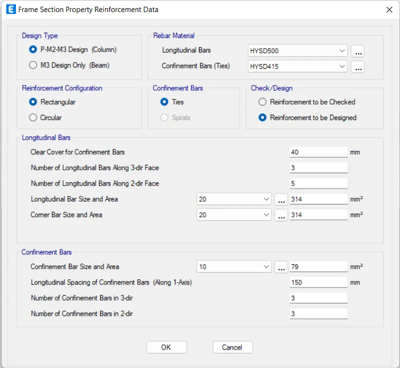
The New column data will be added then click on ok.
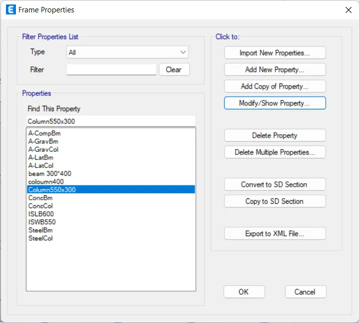
Now select the columns by the select option then assign the new column property
Then Refresh the view from view tab
The the assigned view will displayed like below
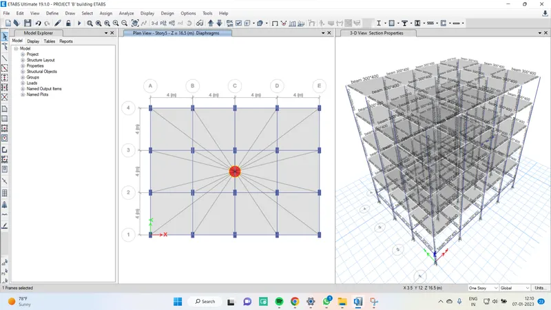
Now save it as building C Then Click on Run analysis.
Building "D" :
It is same as C building but inverse in column sizes change the sizes and assign it.
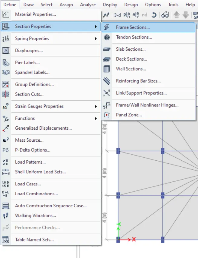
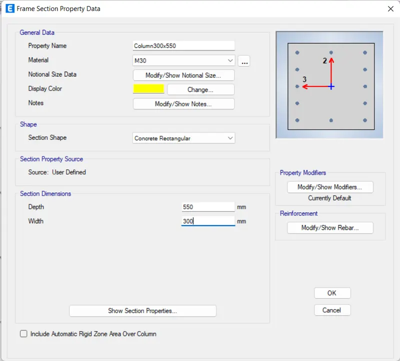
Now click on ok Then refresh the view.
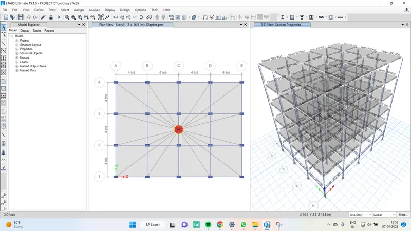
Now save it as building D then clcik on Run analysis.
Building E :
The building E has 10 stroys and then upper column sizes (400x400) and bottom column sizes are (600x600)
First go to edit tab > edit grip
Then the window will popup
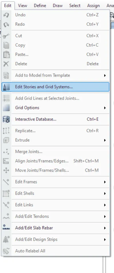
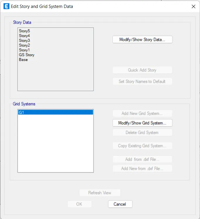
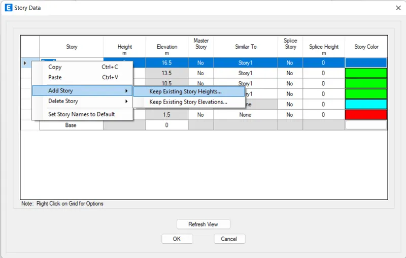
Now we have to add 5 stroyes
Go to modify option and then update to 5 storyes
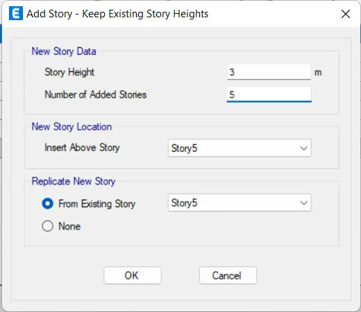
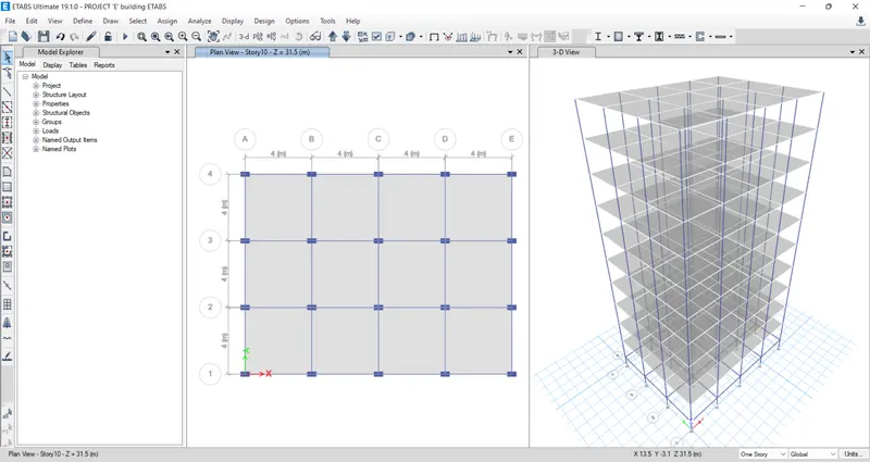
Once check the loads are assign to new levels then move on
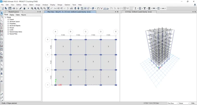
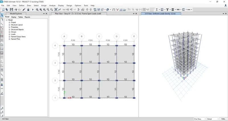
Now go to define
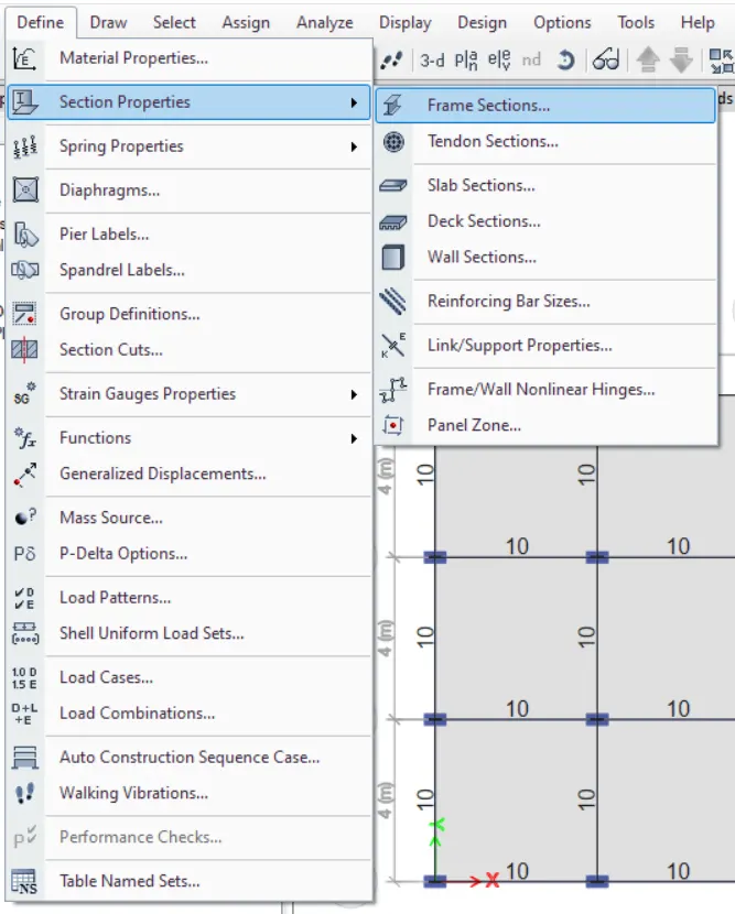
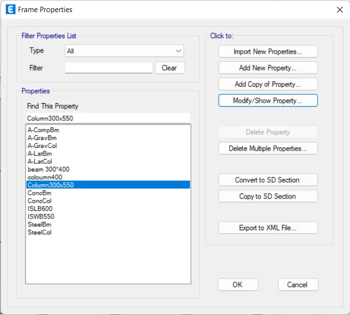
Change the section property then click on ok
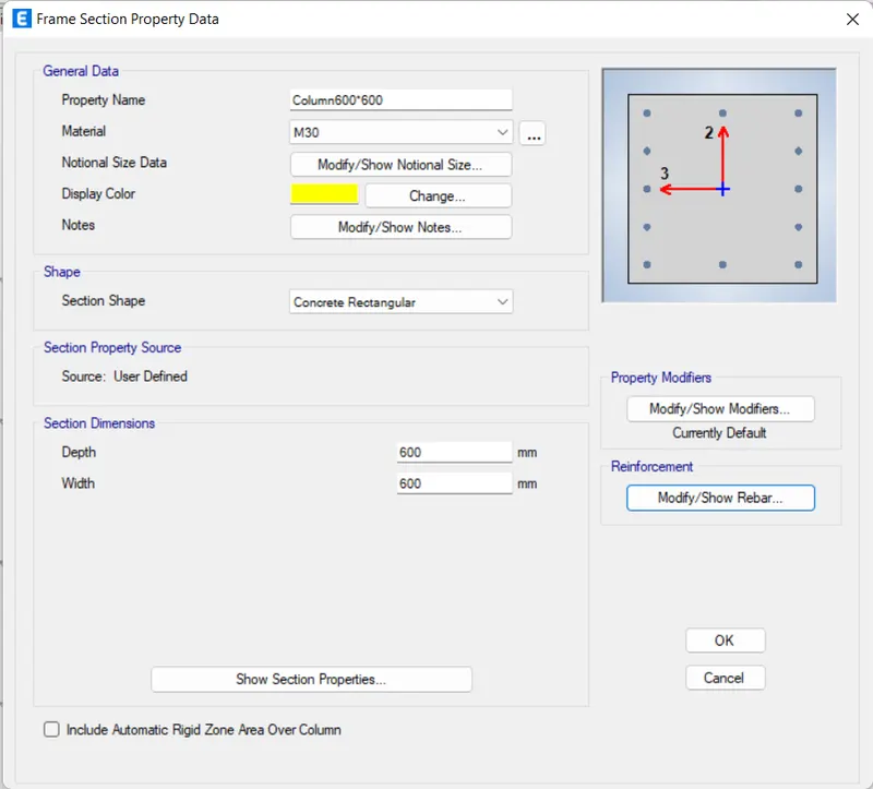
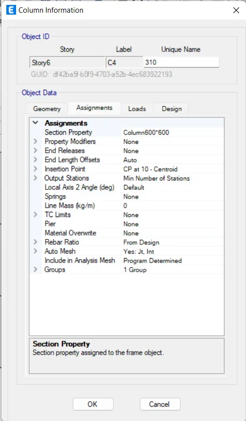
All the columns sections size as changed
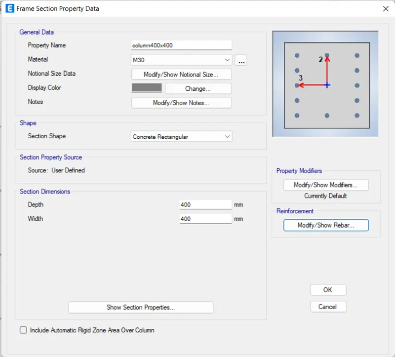
NOw create a new section property foe the column size (400*400)
For that again go the the secetion option then select new section
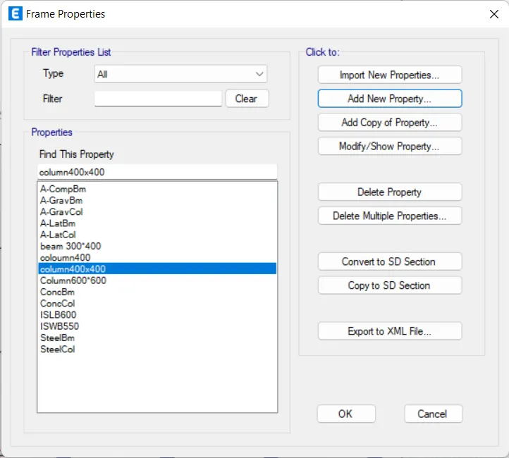
Now we have to assign the 400 column size for the upper 5 storys for that we have to hide the bottom storys
We have to open the set view option from view tab then hide the bottom strorys
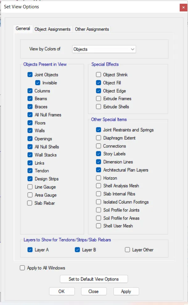
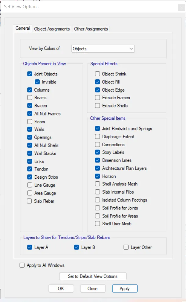
We have to un check the beams and floor then the beams and slabs will hide
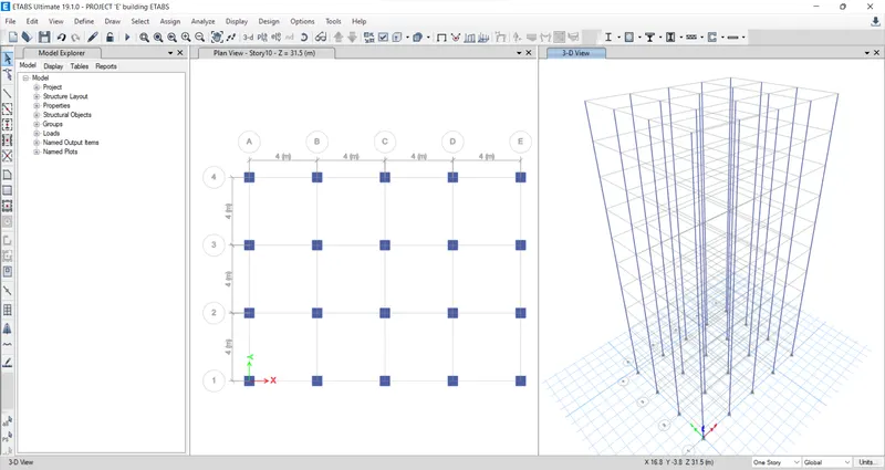
Now go to the view option
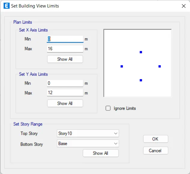
Change the setting story range
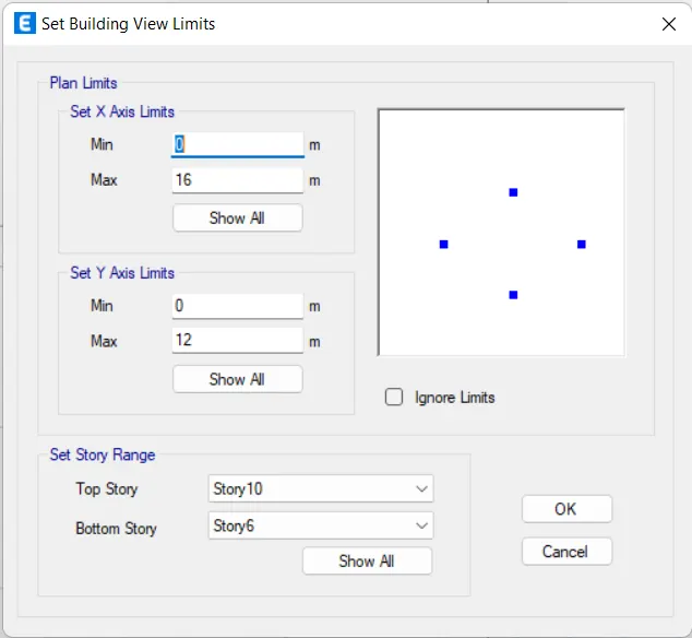
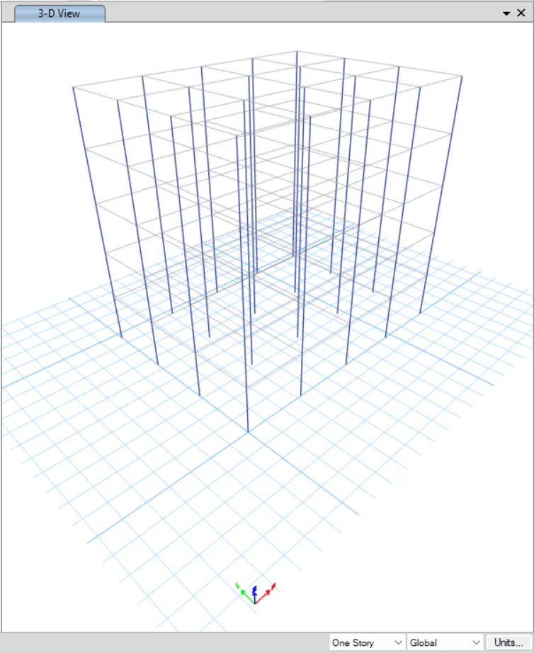
Now select the column by using cursor
Then assign the section (400x400) property to the selected columns
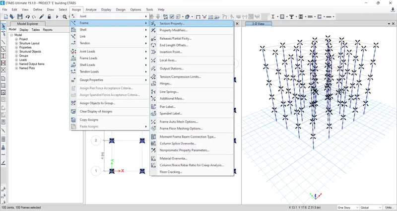
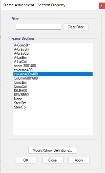
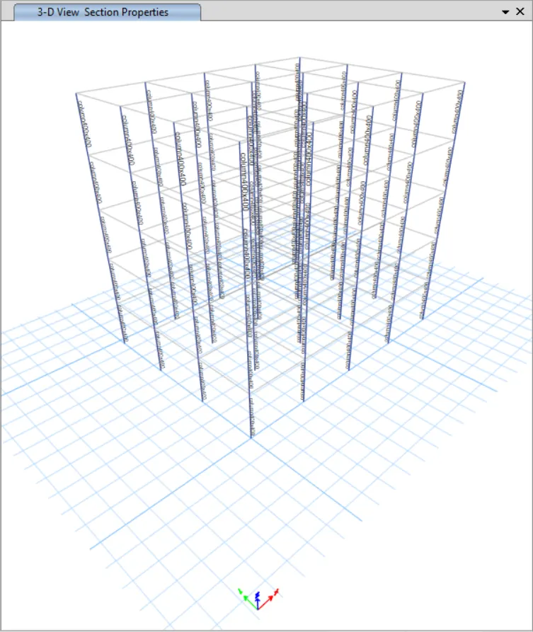
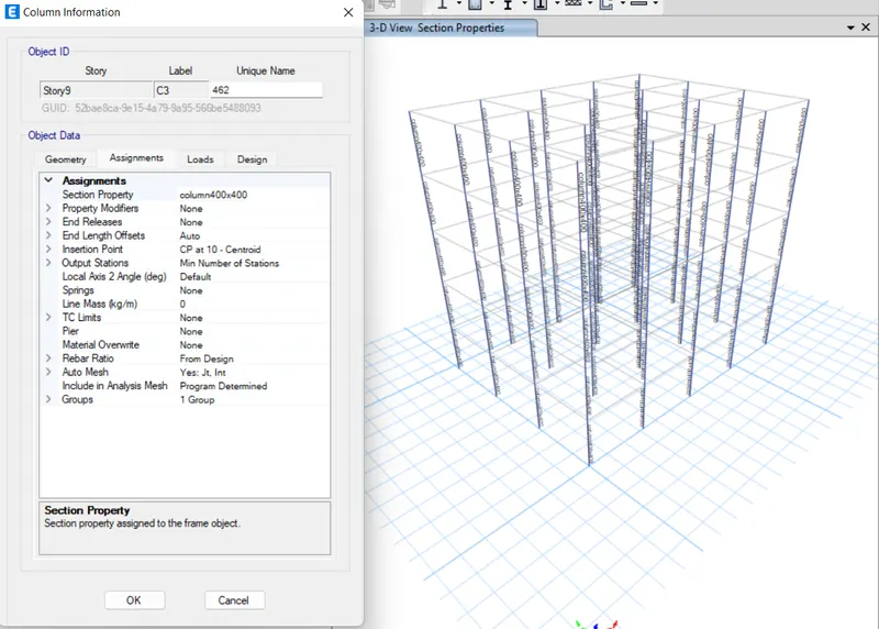
Now go to the view option check all items then the full building view will unhided
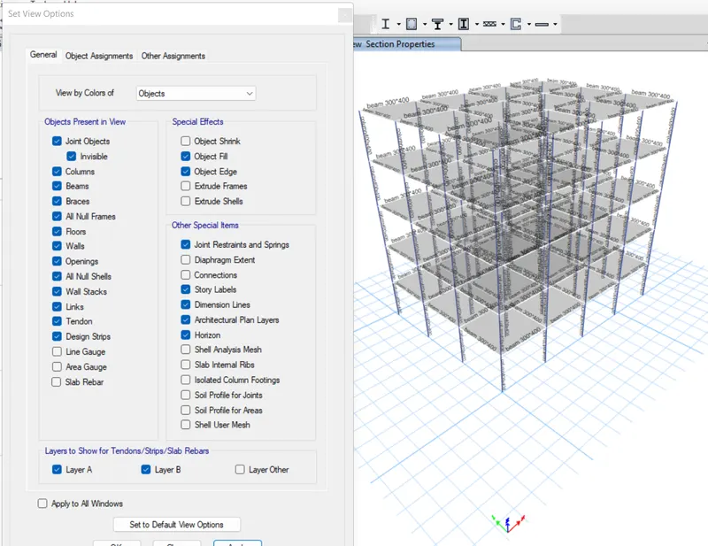
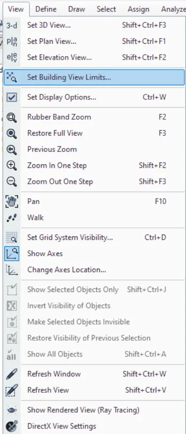
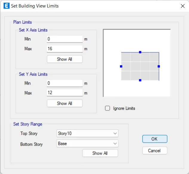
Change the building limits from view tab
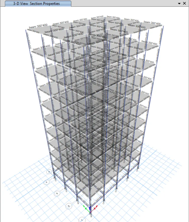
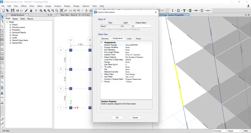
Once check the column sizes
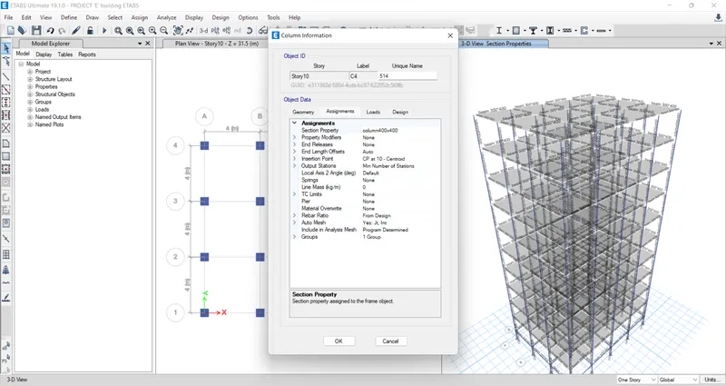
Now apply the diaphgram
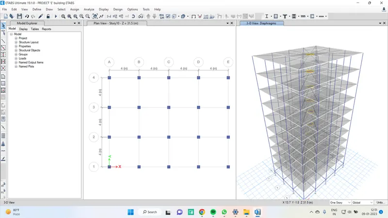
Now click on Run analysis then save the project
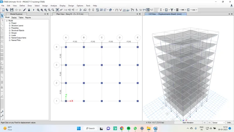
Building F:
In this building we have column sizes (600x600) for all storys
And all remains as the building "E"
Now go to the select tab select columns then assign the section properties as (600x600)
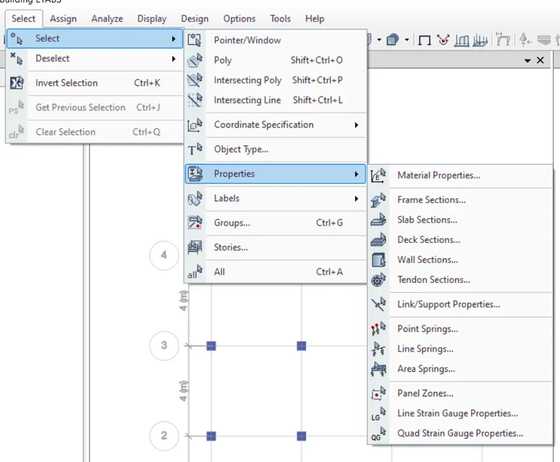
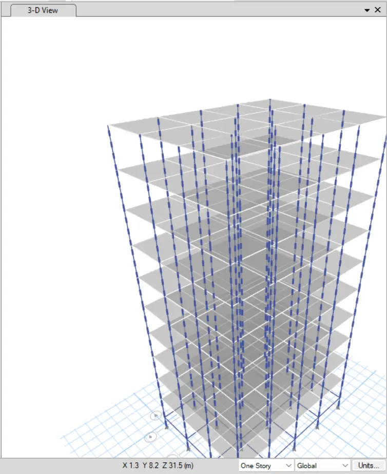
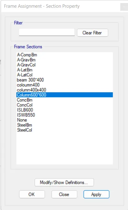
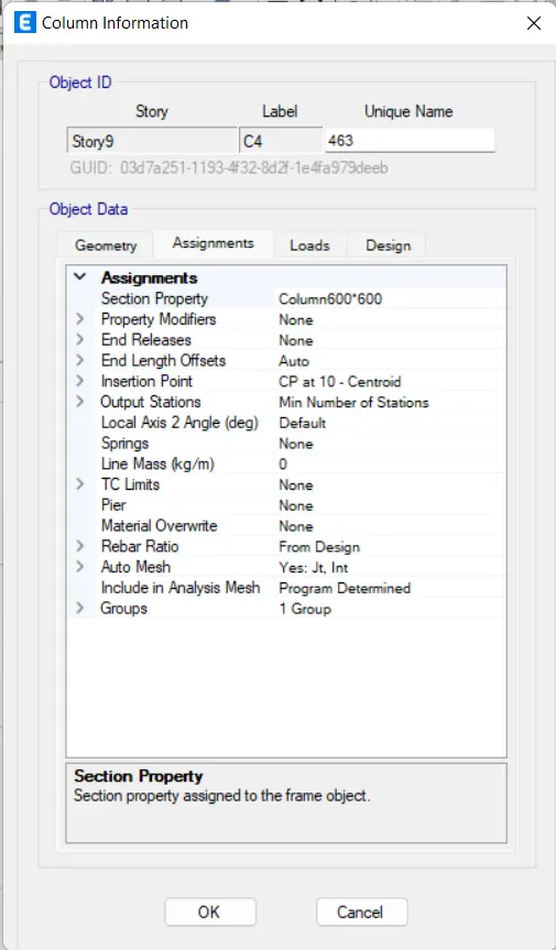
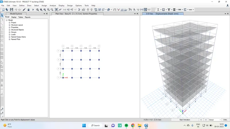
Check the diaghapram if not assign then save the file as Building f then run analysis.
Building G :
Building column sizes base to 10 story we have (800x800)
11 to 20 we have (600x600)
21 to 25 we have (400x400)
First we have to add the storys for that open the story edit option then add stroys
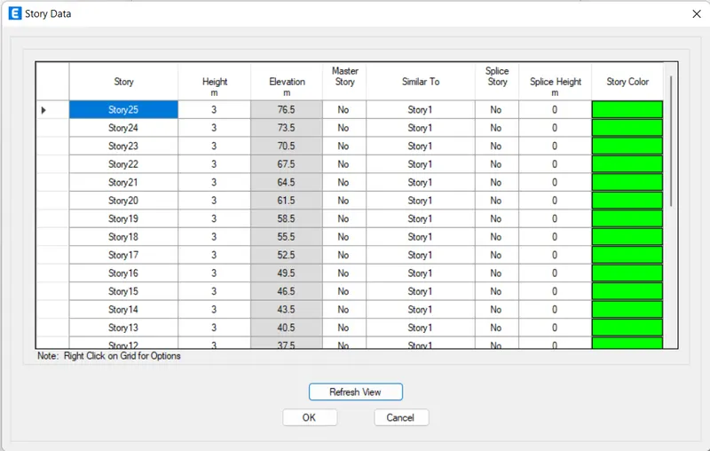
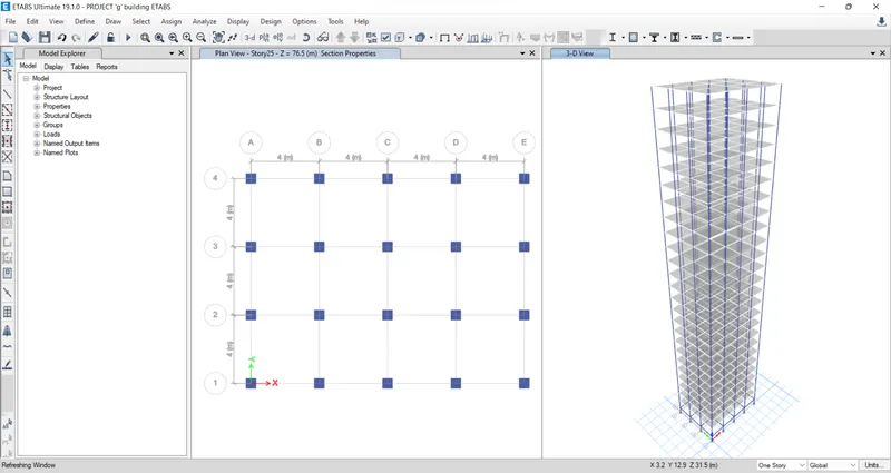
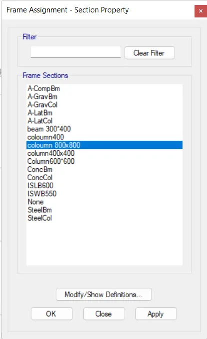
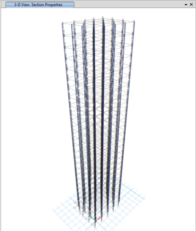
Select all columns and assign the 800x800 column sizes
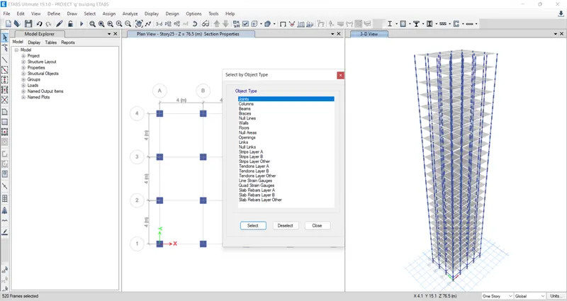
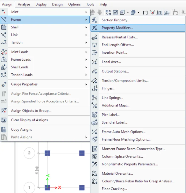
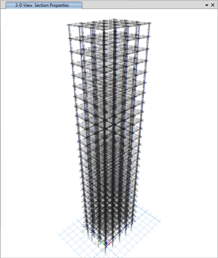
Now hide all beams and floors
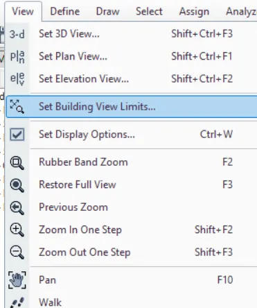
Now go to building limits and chnage it to 11 to 20 and select all columns then assign the cloumn 600x600 column sizes
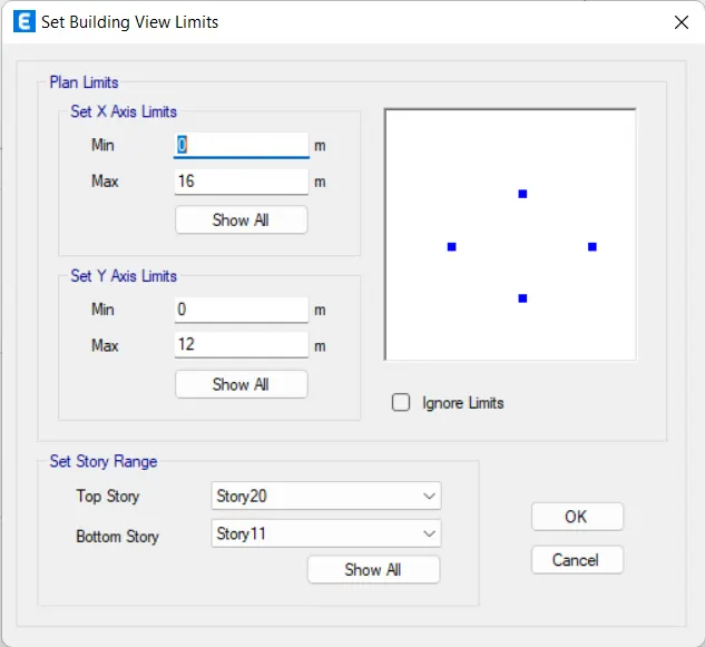
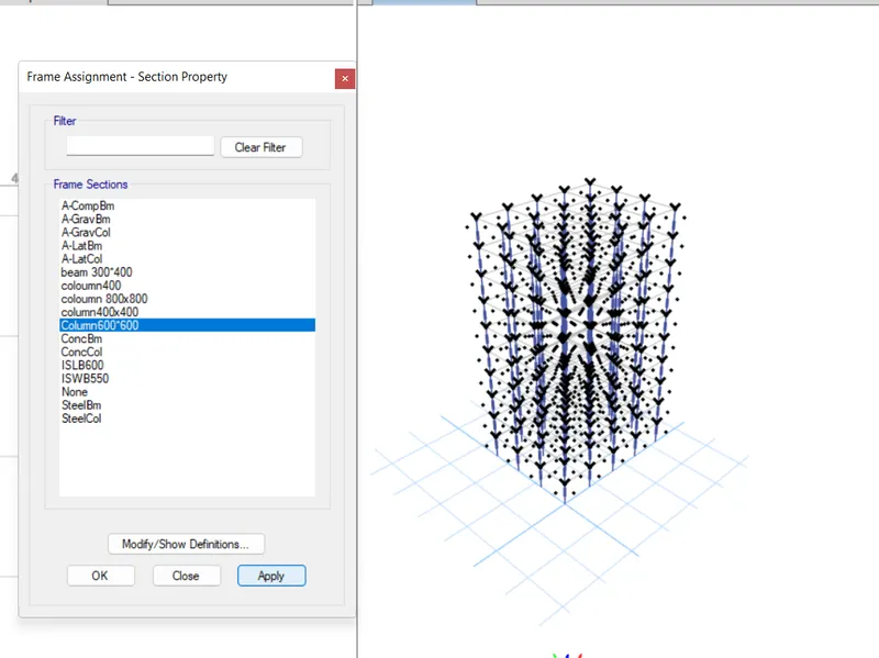
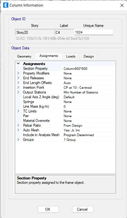
Now change the building view limits and then select the last 5 story cloumns then select then assign the secction property as (400x400)
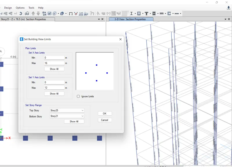
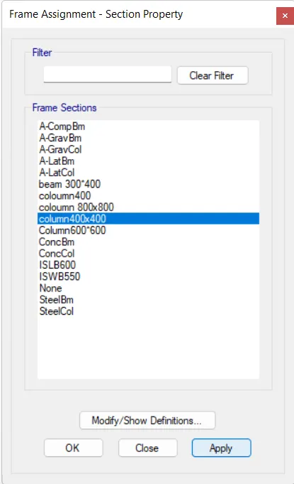
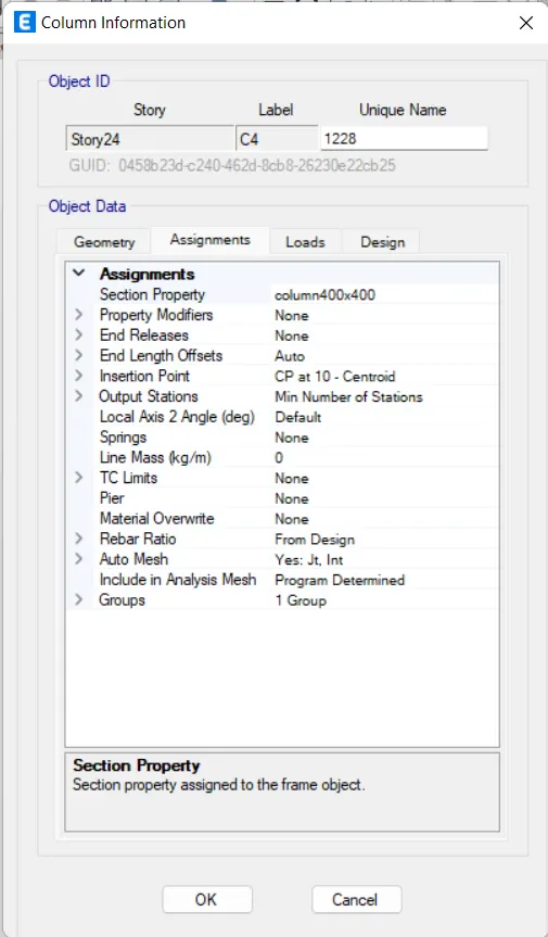
Now once check the columns
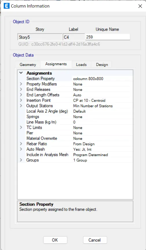
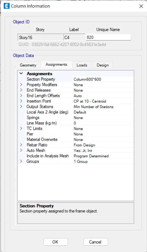
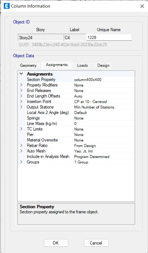
Now assign the diaphgram the click on run analysis
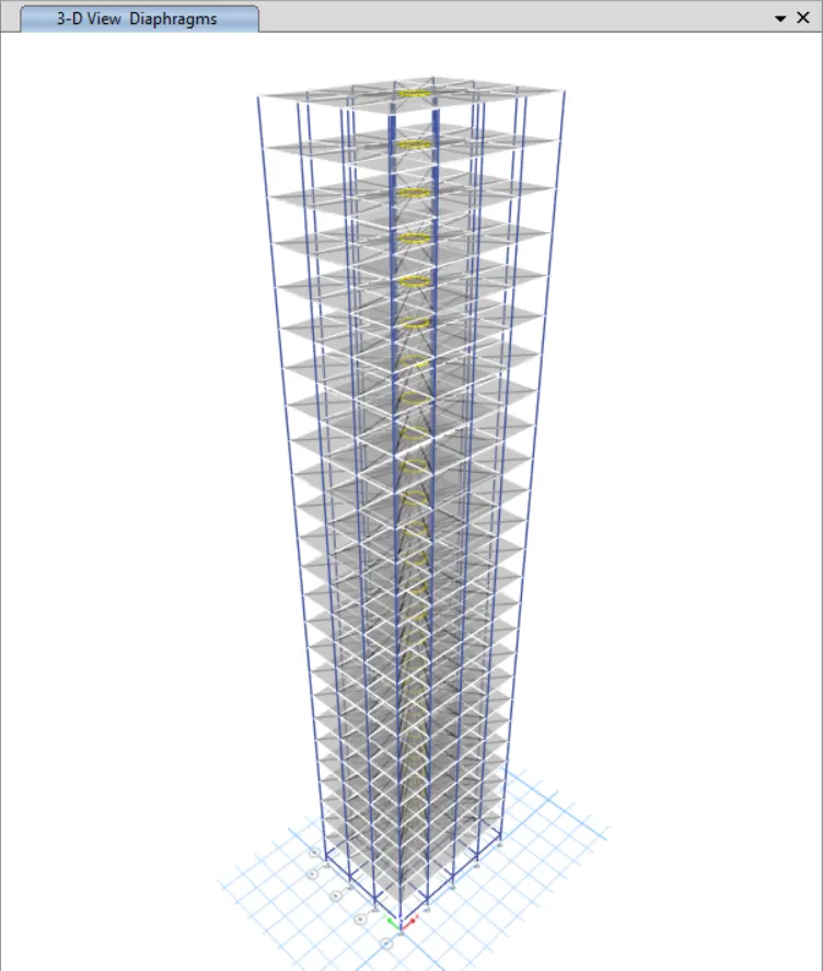
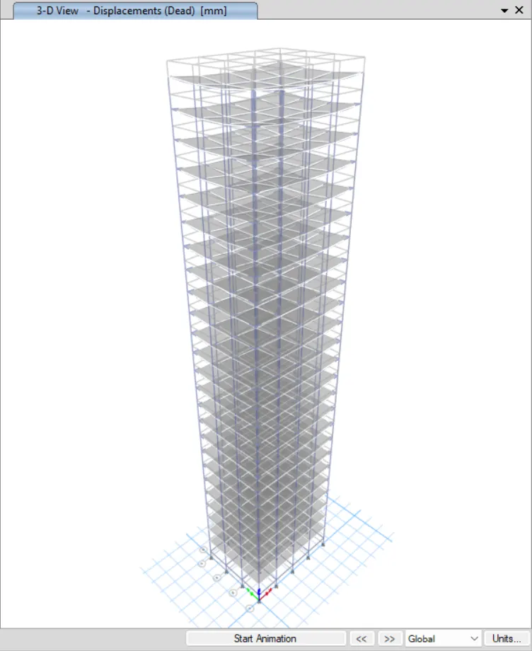
Then save the project.
Building H :
In this we have all 25 storys have save section columns (800x800)
select all columns by using the select option then assign the section properties
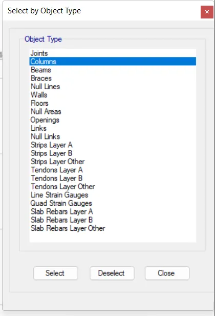
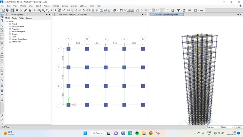
Now save the file then click on click on run analysis
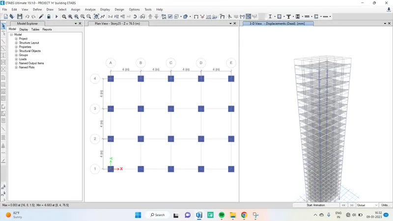
Building J :
In this we have to increase the imposed mass 10%
NOw we have to select the shells
Then assign the incresed impposed mass
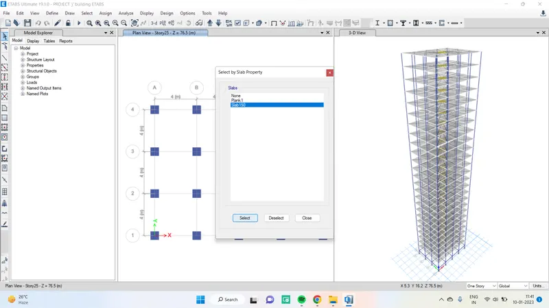
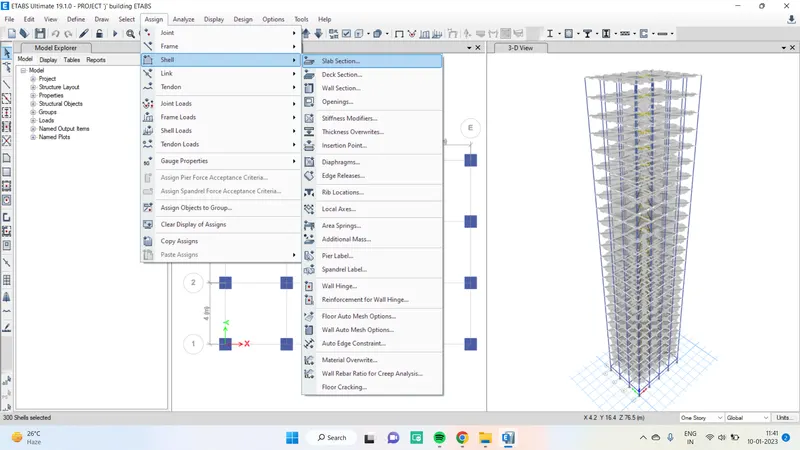
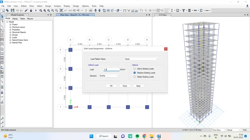
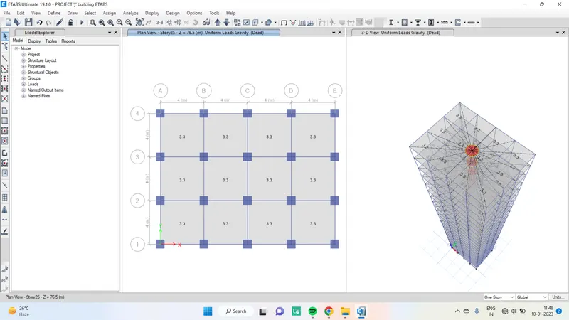
Now save the project then click on run analysis.
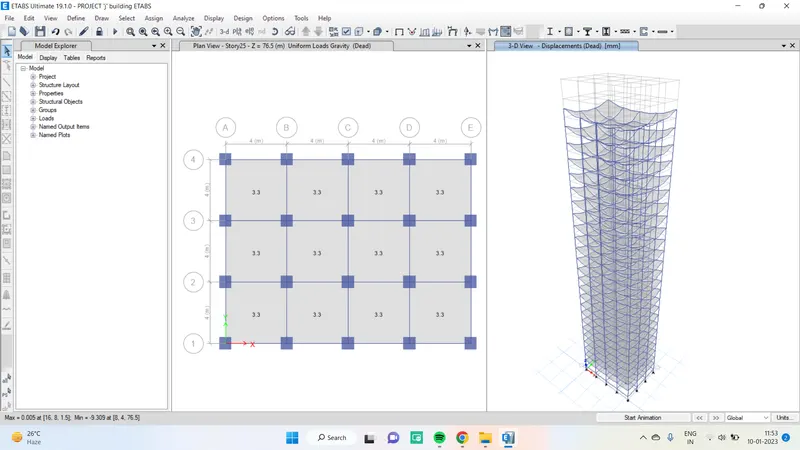
Building K:
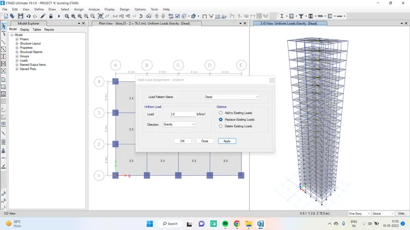
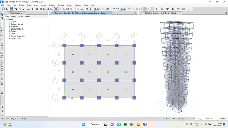
In this we have increse the imposed load to 20%
In the same way we have to increase the load to 3.6
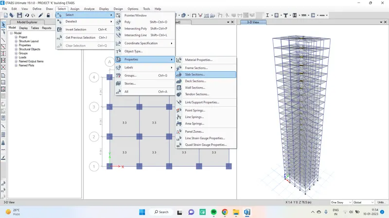
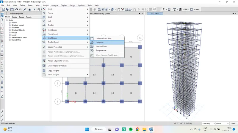
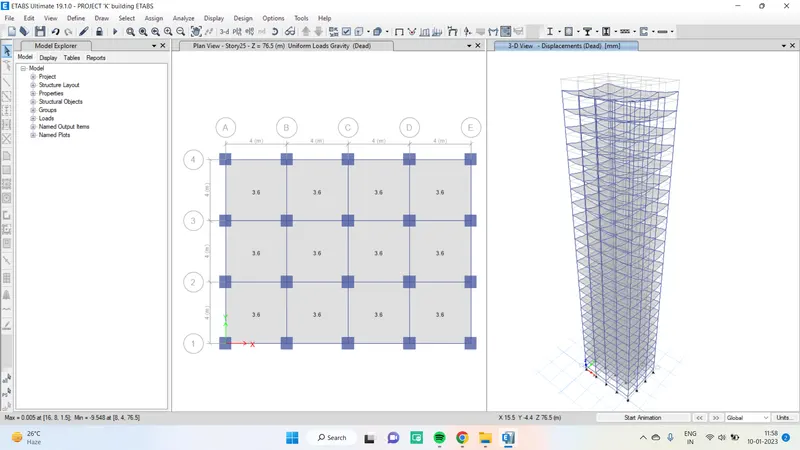
Now save the project and Run analysis
Modal Response for Building A:
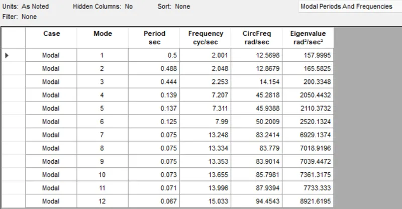
Modal Response for Building B :
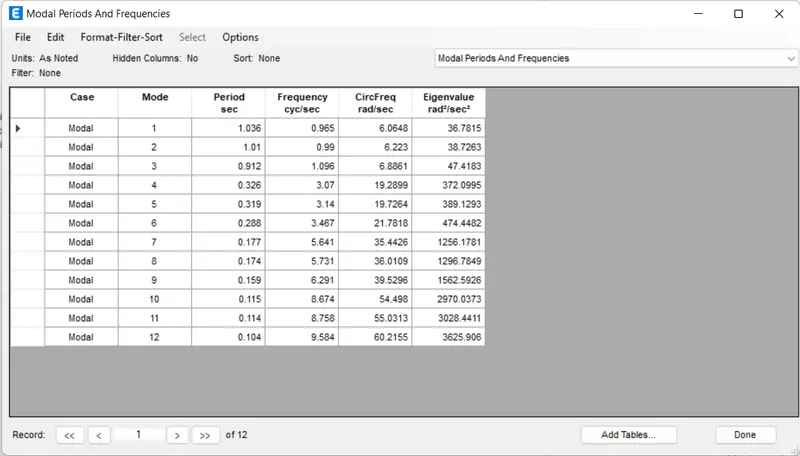
Modal Response for Building C:
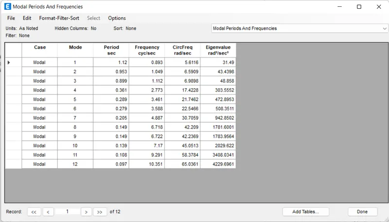
Modal Response for Building D:
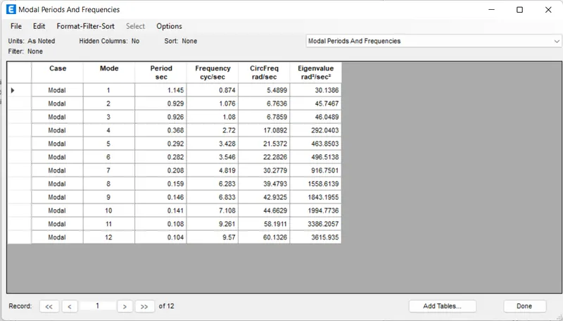
Modal Response for Building E:
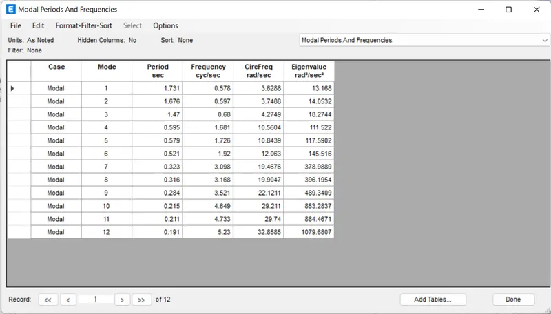
Modal Response for Building F:
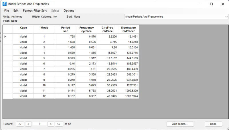
Modal Response for Building G:
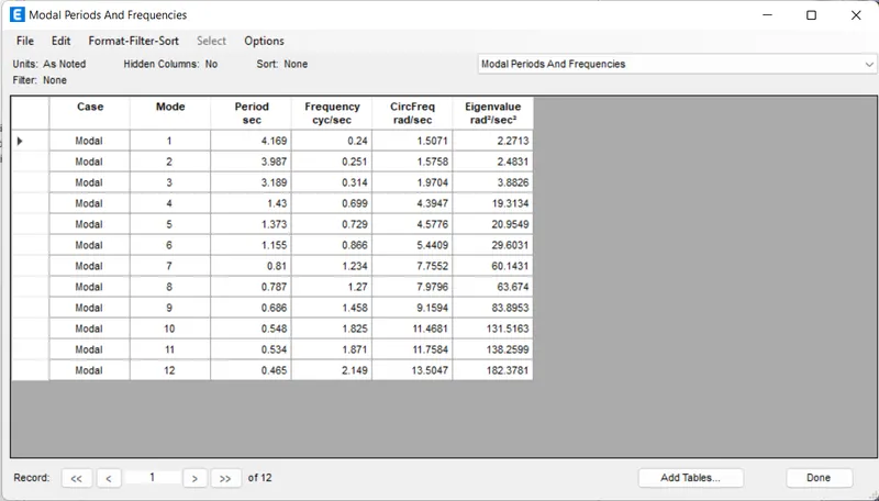
Modal Response for Building H:
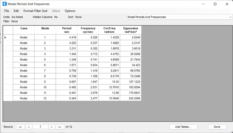
Modal Response for Building J:
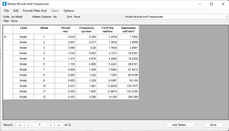
Modal Response for Building K
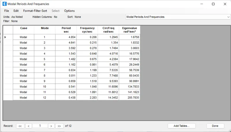
1. Effect of stiffness on T: Compare fundamental natural periods of buildings E & F as well as G & H. Why is there a marginal or significant difference in the fundamental natural periods?
| MODEL NAME | NO. OF STOREYS | COLUMN DESIGN SPECIFICATIONS | NATURAL PERIOD (sec) |
| BUILDING E | 10 | Upper 5 storeys: 400x400 | 1.731 |
| Bottom 5 storeys: 600x600 | |||
| BUILDING F | 10 | Consistent column size throughout: 600x600 | 1.735 |
| BUILDING G | 25 | Upper 5 storeys: 400x400 | 4.169 |
| Middle 10 storeys: 600x600 | |||
| Bottom 10 storeys: 800x800 | |||
| BUILDING H | 25 | Consistent column size throughout : 800x800 | 4.416 |
Conclusion:
For buildings E and F, varying column design doesn't make a big difference as there are only five stories. However, we can see that for buildings G and H, the consistent column size throughout the structure causes a more natural period. Therefore, it can be concluded that providing larger columns at the base and then reducing the size on top floors helps control the natural period 'T' for tall building
2. Effect of mass on T: Compare fundamental natural periods of buildings H, J and K. Have the buildings become more flexible or stiff due to change in mass?
| MODEL NAME | NO. OF STOREYS | PERCENTAGE INCREASE IN MASS | NATURAL PERIOD (seconds) |
| BUILDING H | 25 | Regular mass with no increment | 4.416 |
| BUILDING J | 25 | 10% mass increment | 4.819 |
| BUILDING K | 25 | 20% mass increment | 4.854 |
Conclusion:
As seen from the table, the natural period for the tall buildings is directly proportional to the imposed mass of the building.
3.Effect of Building Height on T: How do the fundamental natural periods of Buildings A, B, F, and H change with a change in building height?
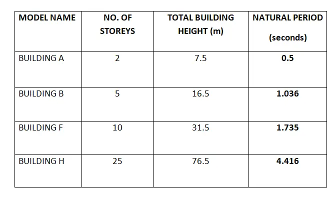
Conclusion: As indicated in the above table, the natural period 'T' is also directly proportional to the building height.
4.Effect of Column Orientation on T: How do the fundamental natural periods of Buildings B, C, and D change with a change in column orientation?
Conclusion:
When the column cross-section is square, there's not much difference between the lateral displacement in both the orthogonal directions. However, when you orient the column in a particular direction be it X or Y, the lateral displacement in that particular direction will be less than that in the other direction which has a lesser column length.
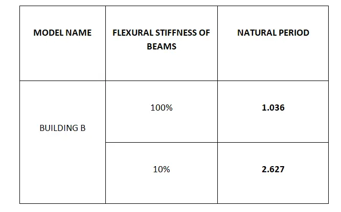
5.Effect of Flexural Stiffness of Structural Elements on mode shapes: Compare fundamental mode shape of Building B in two situations when the flexural stiffness of beams relative to that of adjoining columns is very small versus when it is large.
Conclusion:
It is pretty obvious that if you decrease the flexural stiffness of beams, the overall flexural strength of the beam is also going to reduce, and consequently, the fundamental natural period will shoot up.
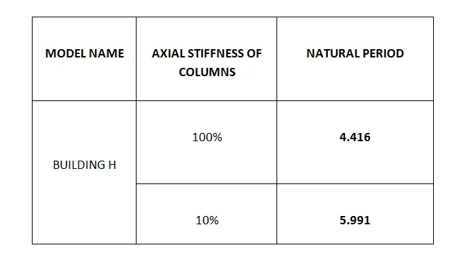
6.Effect of Axial Stiffness of Vertical Members on mode shapes: Compare the fundamental mode shape of Building H in two situations when the axial cross-sectional area of columns is very small versus when it is large.
Conclusion:
As the axial stiffness of columns decreases, the fundamental natural period of the building increases regardless of its structural geometry.
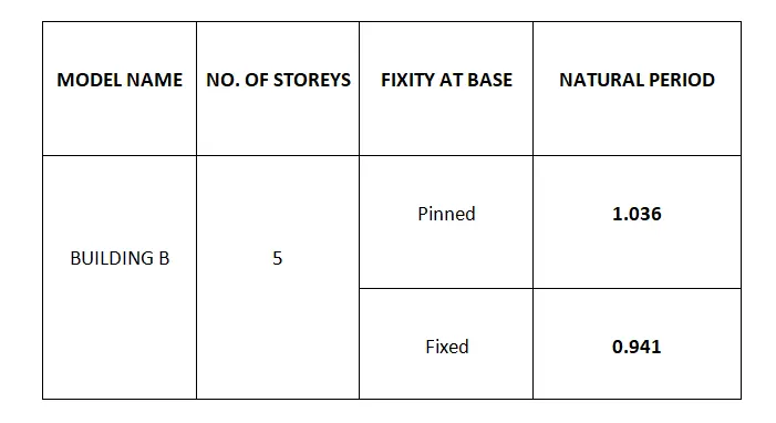
7.Effect of Degree of Fixity at column bases on mode shape: Compare the fundamental mode shape of Building B in two situations when the base of columns is pinned versus when it is fixed.
Conclusion:
It is evident that pinned support offers fewer restraints compared to the fixed one which leads to more movement and thus increased natural period. As a result, it can be concluded that the fixed support will give you better control over the fundamental natural period of buildings.