Project 1_Comparative study of different storey buildings for Seismic forces
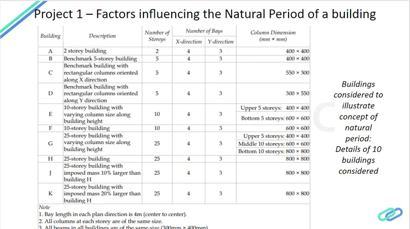
Aim-To do Comparative study of different storey buildings for Seismic forces.
Introduction-
Structural Element Sizes
- Beams : 300 × 400 mm
- Columns : 400 × 400 mm
- Slab : 150 mm thick
Material Properties
- Grade of Concrete : M30
- Grade of Steel Reinforcement Bars : Fe 415
Loading
- Dead Load on beams from infill wall : 10 kN/m
- Live load on floor : 3 kN/m2
Buildings are assumed to be pinned at base
Procedure-
BUILDING-A
-Open ETABS
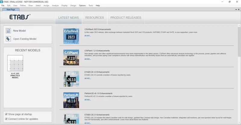
-Select New model
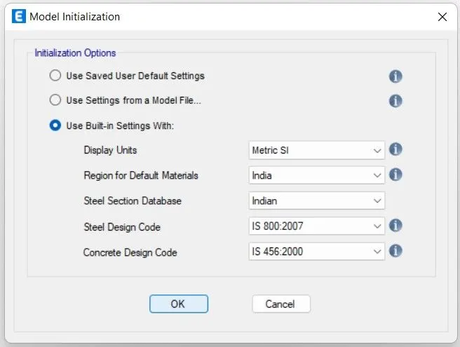
-set metric as a unit and set Is code
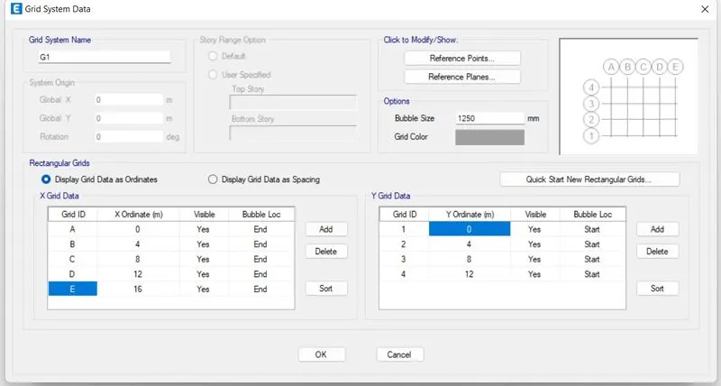
-Select customised grid option>Click on edit>following window display as per given set grids in x and y direction with respective their dimension as shon below>Ok
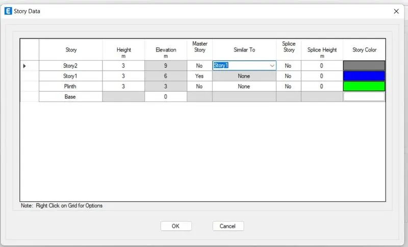
-Select customised story>Select edit option>Rename Story1 as Plinth and remaing as per Sory 1. 2 respectively, make story 1 as a master story and make changes according to that.
-As here only 2 story available so delete remain story
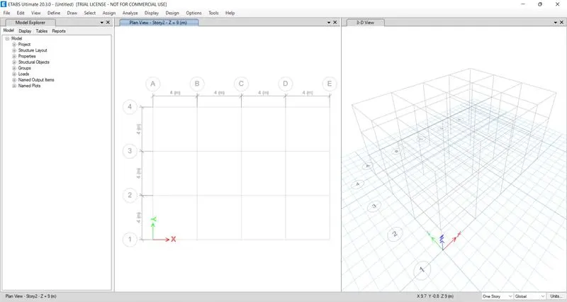
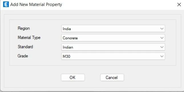
-Select Define>Select Material properties>Select Add new material>Slect Concrete with M30
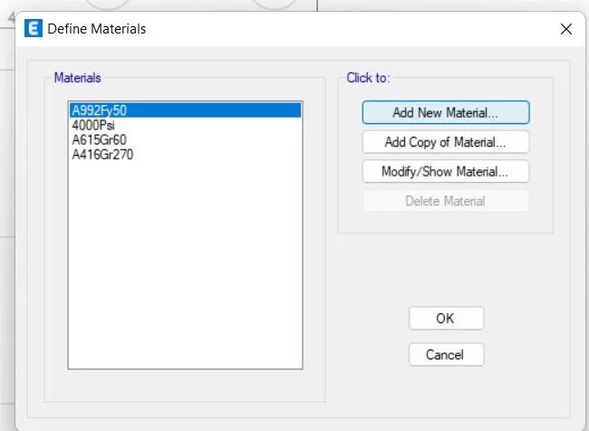
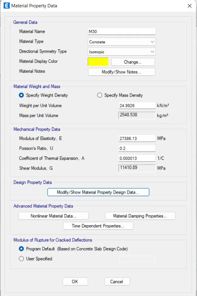
-To give material Select Define>Select material>Selet Add new material>Add rebar 415>Ok>Property window shows set as below>Ok
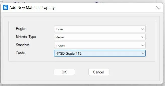
-Now add sections
-Select Define>Select section properties>Select frame section>Select Rectangluar section>Set beam first as name B300x400>give property as shown below>Ok
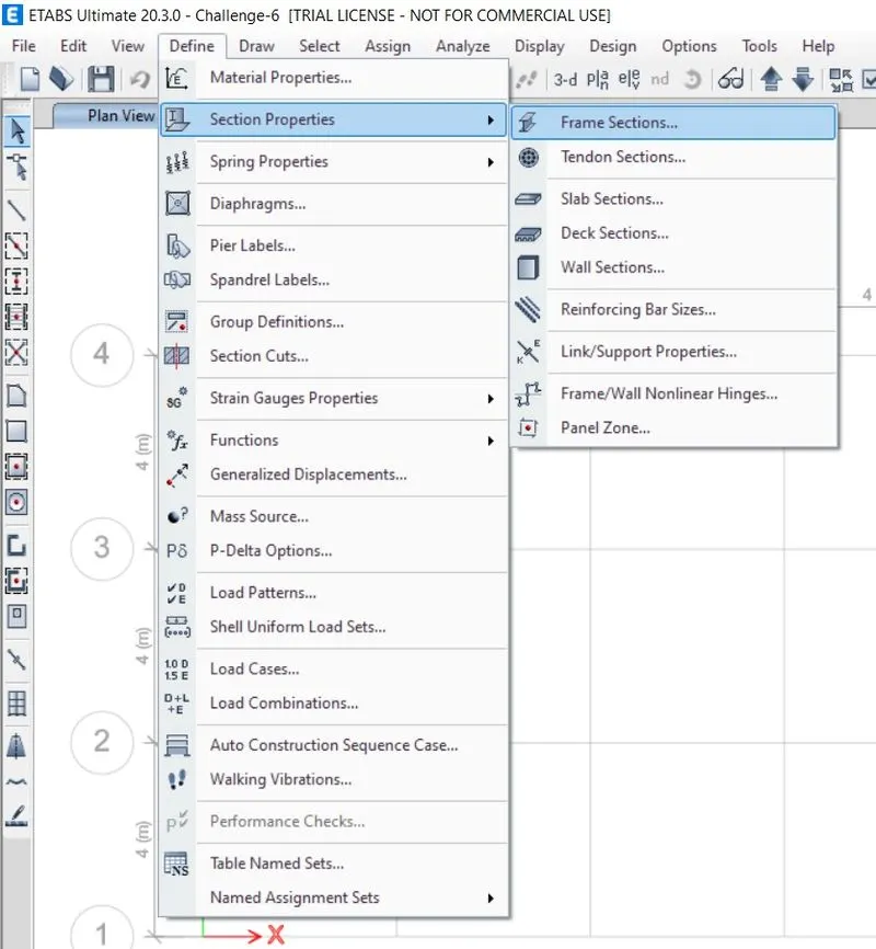
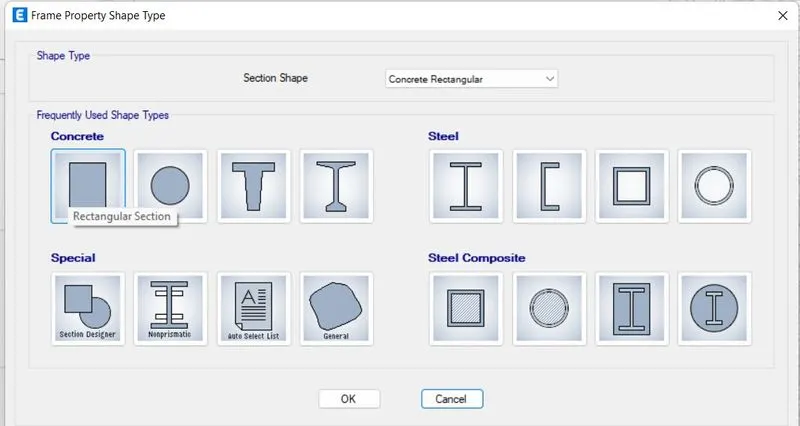
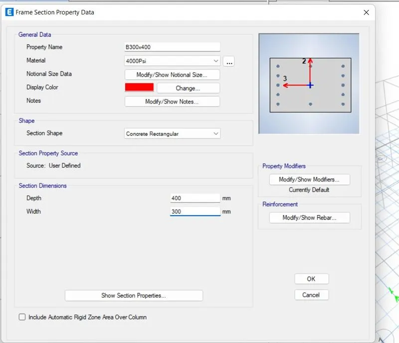
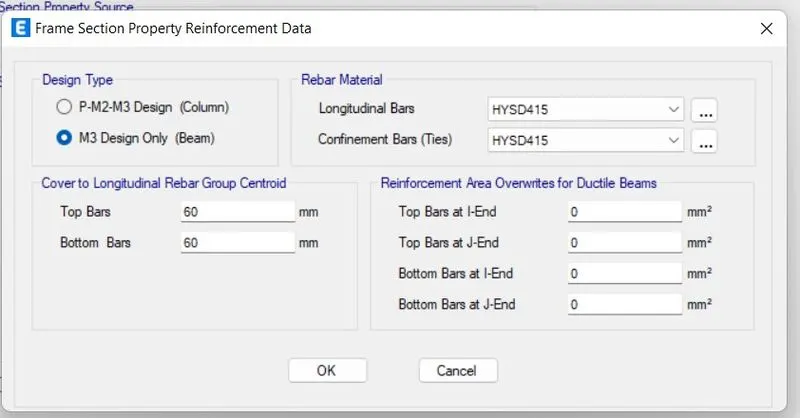
-Select Reinforcement modify>Set grade as 415
-Again add new property as column
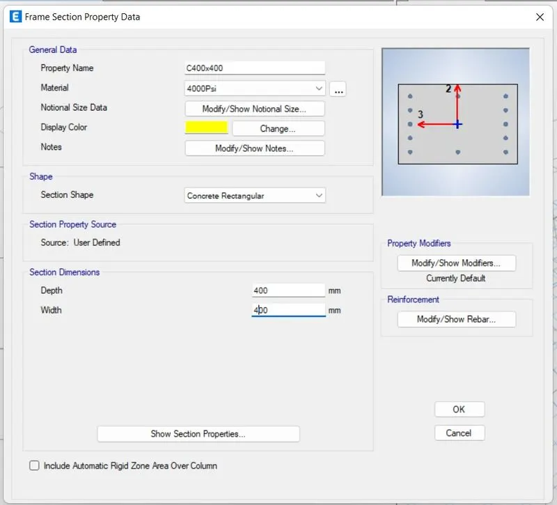
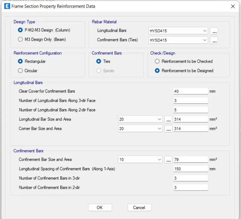
-Select Reinforcement modify>Set grade as 415
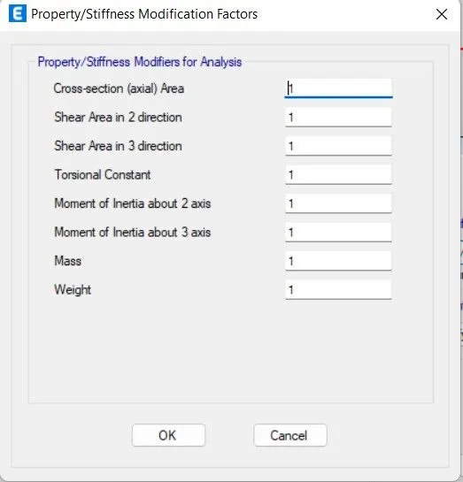
-Select property modifier modify option for now there is no changes
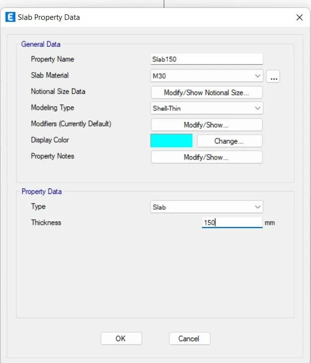
-To add slab section
-Select Define>Select slab section>Select add new slab section with name slab 150>Give thickness 150>ok
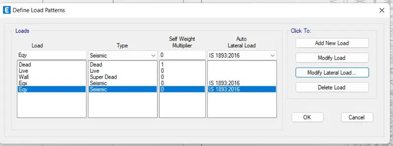
-Add Load
-Select Define>Select Load pattern>there is Dead and Live load already present add wall load and Eqx, Eqy seismic load
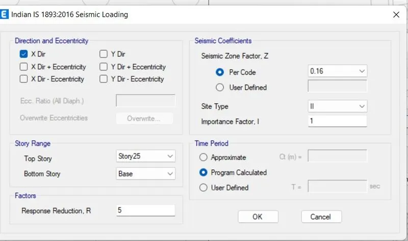
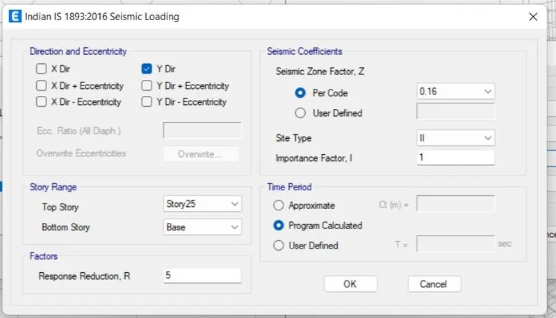
-Now select Eqx>Seelct modify lateral load>Set as given below
-Now select Eqy>Seelct modify lateral load>Set as given below
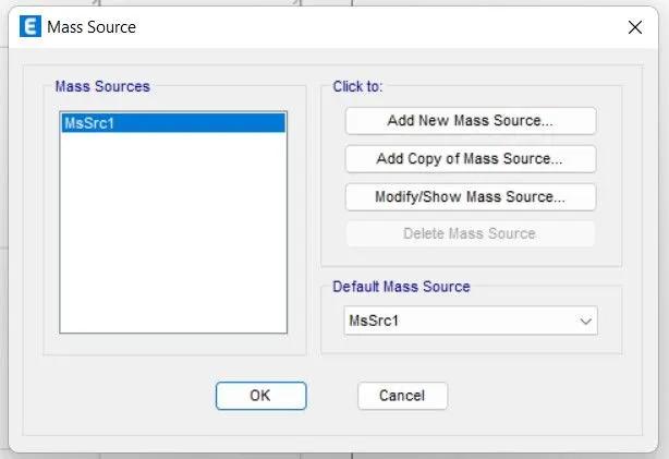
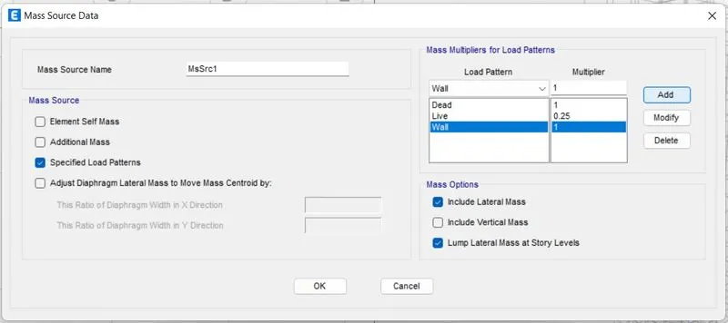
-Select Define>Select mass source>Select present source msrc1>Select modify option>Selection option select and add load with factors respectively>ok
-Now draw column, beams, and slab
-On left hand side select Quick draw column option and select size that we created earlier
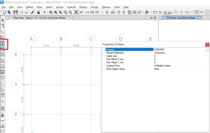
-Draw column at intersection of grids
-First draw column at horizontal then
-Select it and go to Edit>Select Replicate option in dy=-3 and number=3
-On left hand side select Quick draw beam option and select size that we created earlier
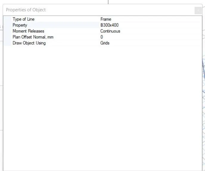
-Start drawing beams by selecting grids and then after selecting beams use Edit>Replicate option
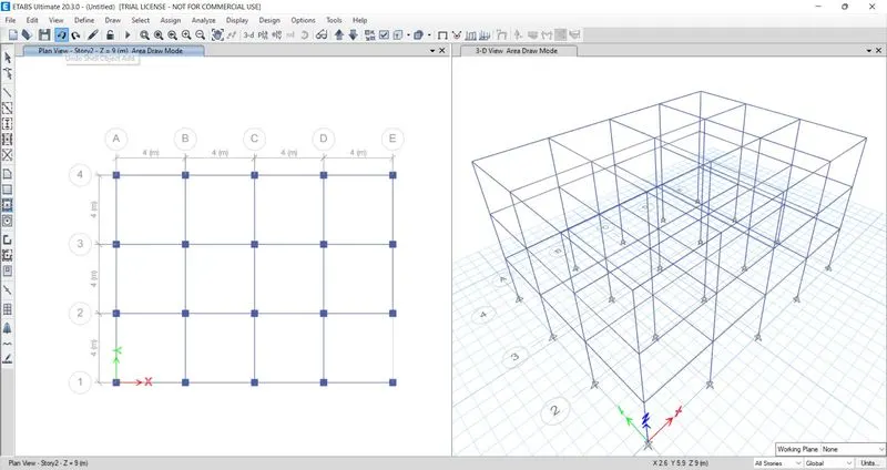
-On left hand side select Quick draw floor option and select size that we created earlier
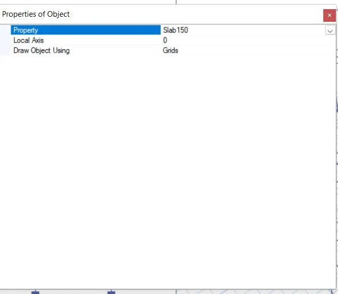
-Click anywhere between particlualr grids and draw slab
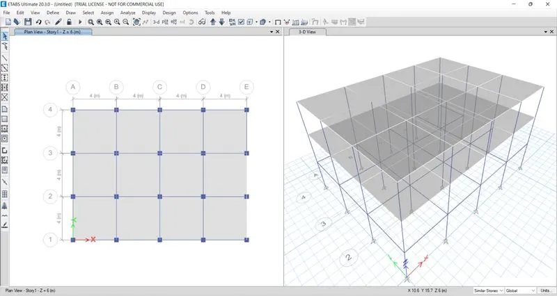
Now assign load to it
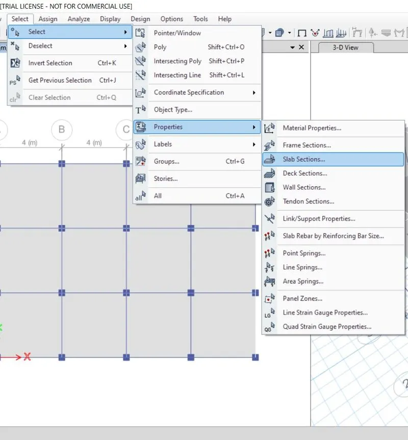
-Go to Select>Select Properties>Select slab section of 150
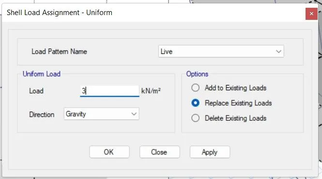
-Go to Assign>Select shell load>Select unifrom>Select live load of 3
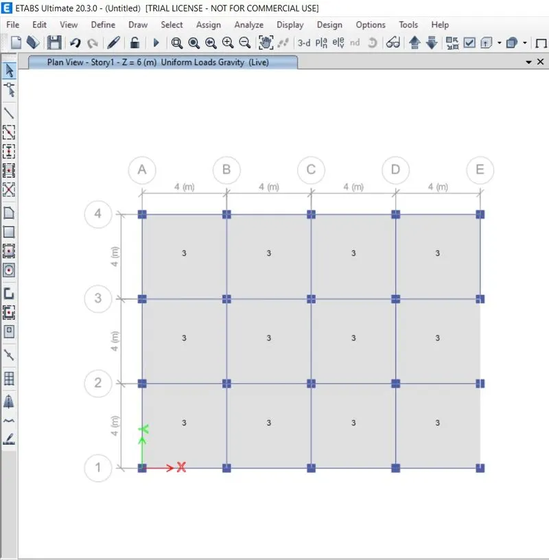
-Now select
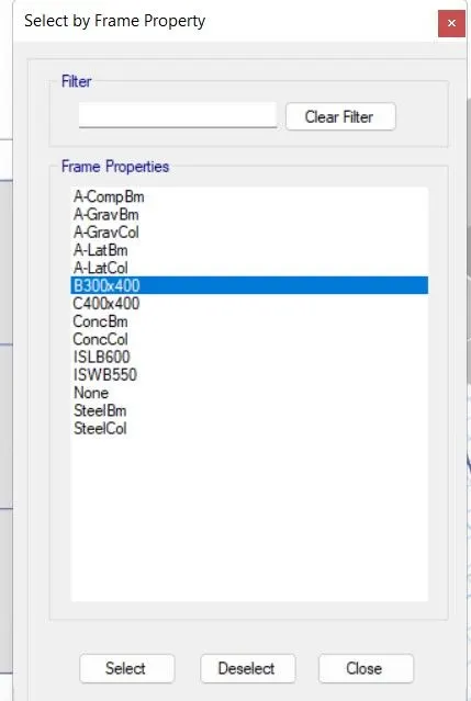
-Go to Select>Select properties>Select frame sections>Select beam
-Go to Assign>Select Frame load>Select Distributed
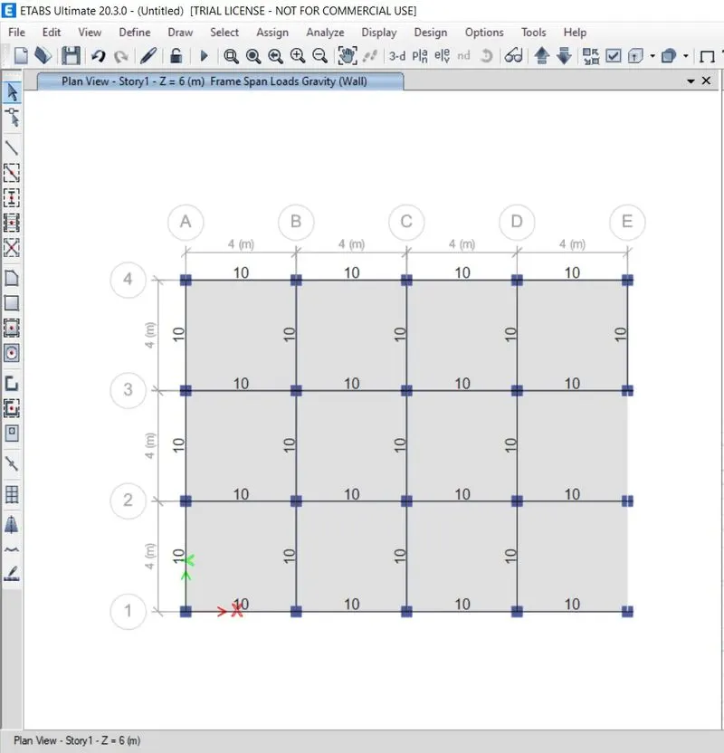
-Go to Select>Select Properties>Select slab section of 150
-Go to Assign>Select shell>Select Diaphgram
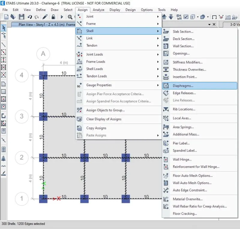
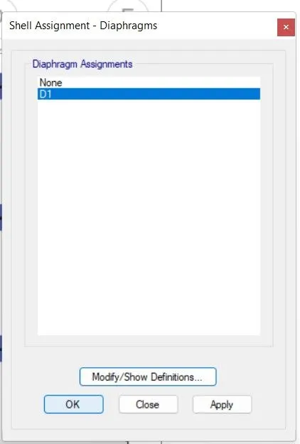
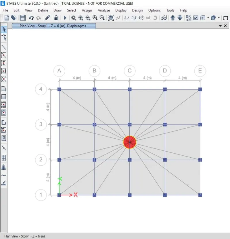
-Now Run Analysis
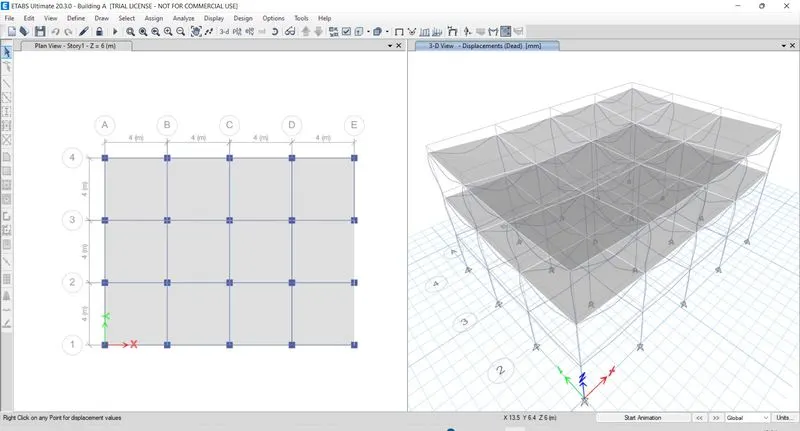
BUILDING-B
-Continue with building A
-Save it as a BUILDING-B
-Here difference is stories are 5 so,
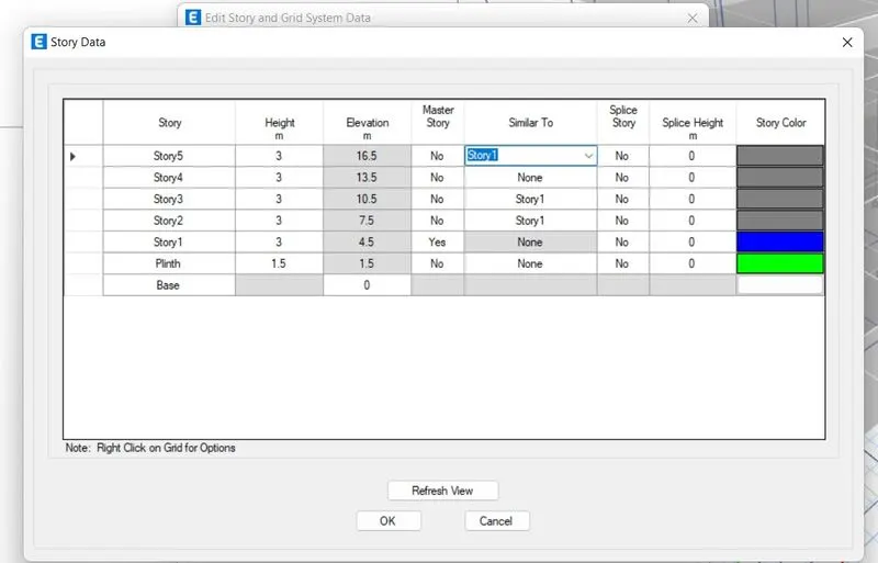
-Go to Edit>Selet edit stories option>Add 3 more stories
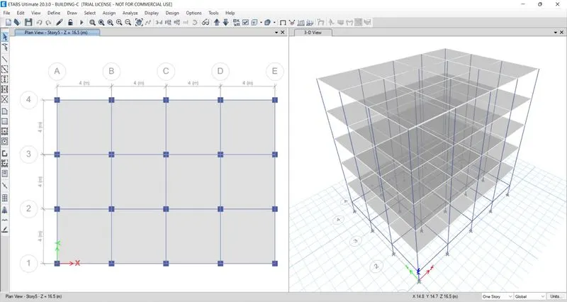
-Check for Frame load and shell load
-Go to Select>Select Properties>Select slab section of 150
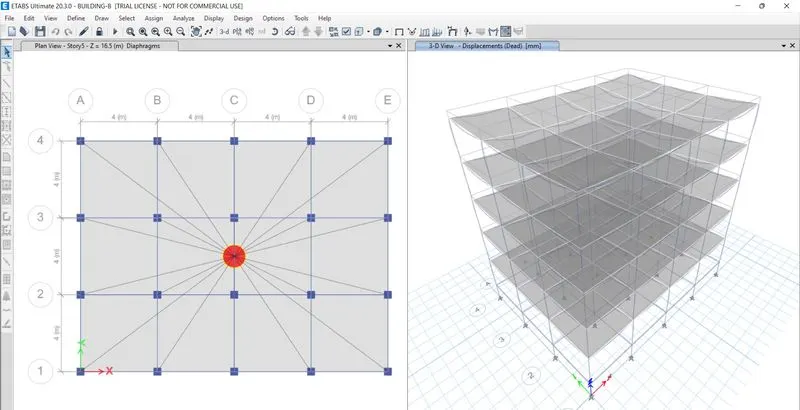
-Go to Assign>Select shell>Select Diaphgram
-Run Analysis
BUILDING-C
-BUILDING-B Save it as BUILDING-C
-Here difference is column size is change
-First select column
-Go to Select>Select properties>Select column
-Go to Define>Select Section properties>Select column>Select modify>Change column size
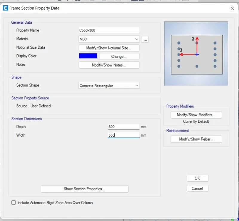
-Now change column orientation
-Go to Select>Select properties>Select column
-Go to Assign>Select frame>Select Local Axes>Change Angle 0 to 90
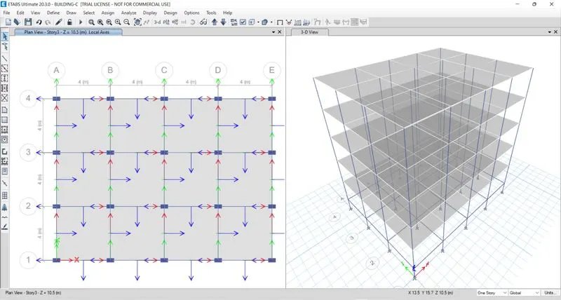
-Go to Select>Select Properties>Select slab section of 150
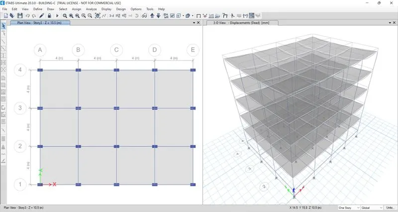
-Go to Assign>Select shell>Select Diaphgram
-Run Analysis
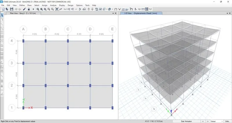
BUILDING-D
-BUILDING-C is save it as BUILDING-D
-Here only change is chnage of angle
-Go to Select>Select properties>Select column
-Go to Assign>Select frame>Select Local Axes>Change Angle 90 to 0
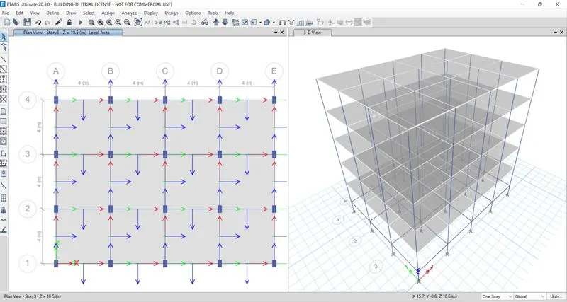
-Go to Select>Select Properties>Select slab section of 150
-Go to Assign>Select shell>Select Diaphgram
-Run Analysis
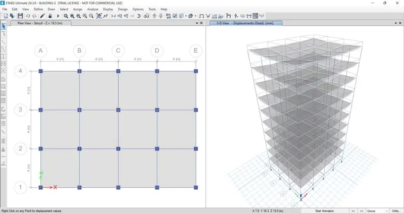
BUILDING-E
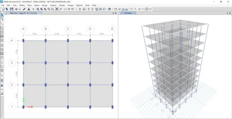
-Building D save it as Building E
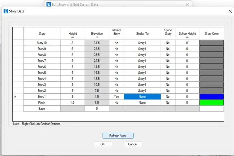
-Here add 5 more stories as building is 10 strory
-Go to Edit>Select Edit stories option>Select modify story>Add 5 story with keep existing height>Refresh view>Ok
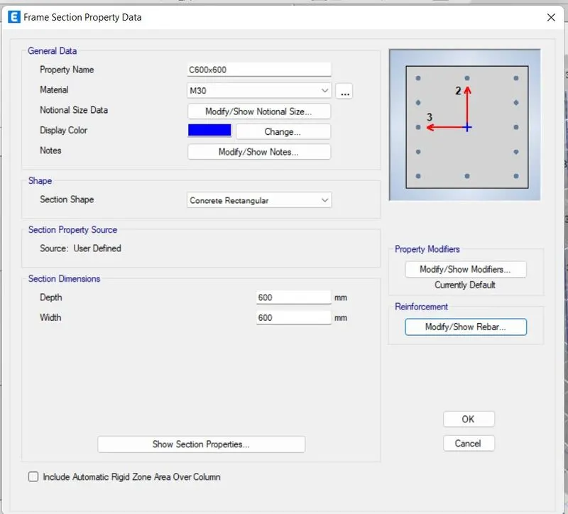
-Change column size
-Go to Select>Select properties>Select column
-Go to Define>Select Section properties>Select column>Select modify>Change column size
-Now add new column
-Go toDefine>Select section property>Select new property>Select rectangular shape>Add name C400x400, add grade 415
-Click on refinforcement modify>Select column>Select 415
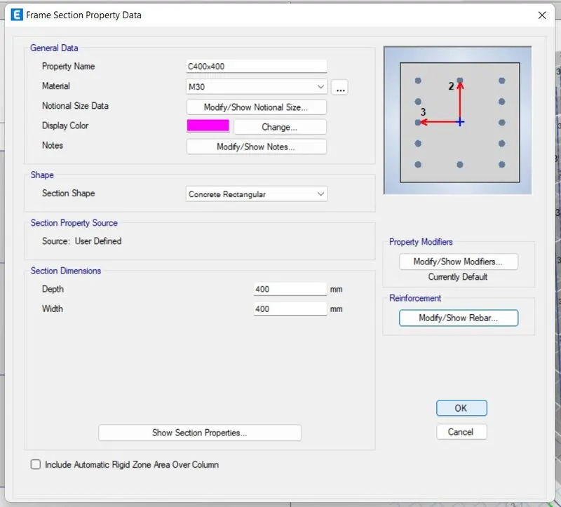
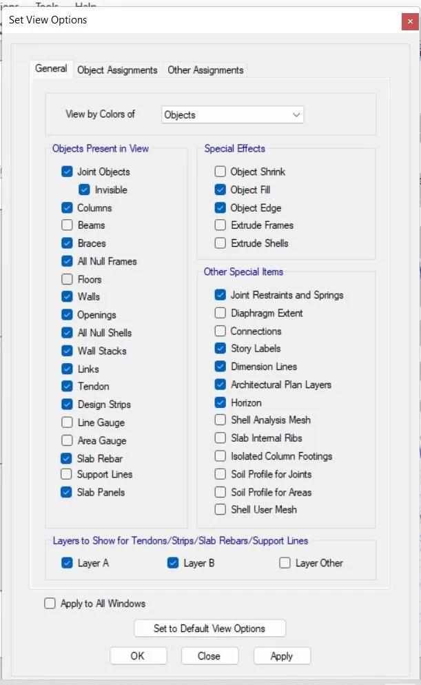
-Now hide beam and floor
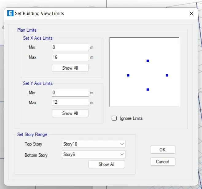
-Go to View>Select set building view option>Set base as story as 6 and top story as 10
-Now select all coliumn present in this view
-Go to Assign>Select Frame>Select section property>Select column 400x400
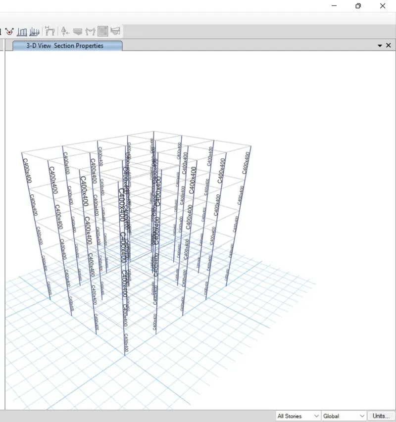
-Now set view as previous and unhide beam and floor
-Go to Select>Select Properties>Select slab section of 150
-Go to Assign>Select shell>Select Diaphgram
-Run Analysis
BUILDING-F
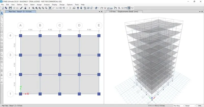
-BUILDING-E save it as BUILDING-F
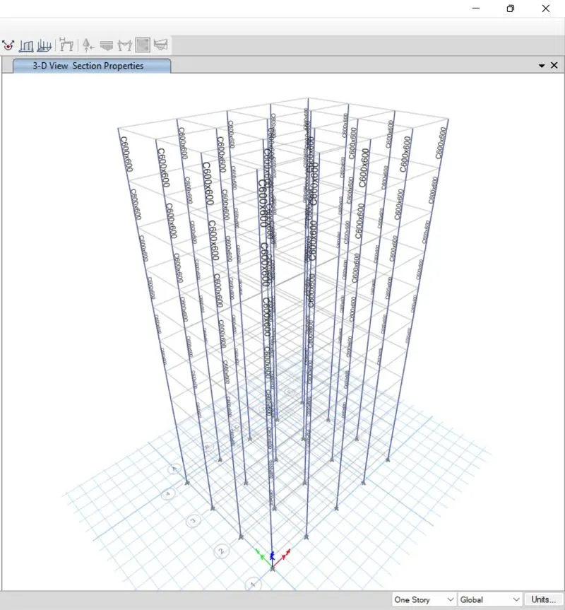
-Here the only change is all columns of 10 story are same size
-Now hide beam and floor
-Go to View>Select set building view option>Set base as story as 6 and top story as 10
-Now select all coliumn present in this view
-Go to Assign>Select Frame>Select section property>Select column 800x800
-Now set view as previous and unhide beam and floor
-Go to Select>Select Properties>Select slab section of 150
-Go to Assign>Select shell>Select Diaphgram
-Run Analysis
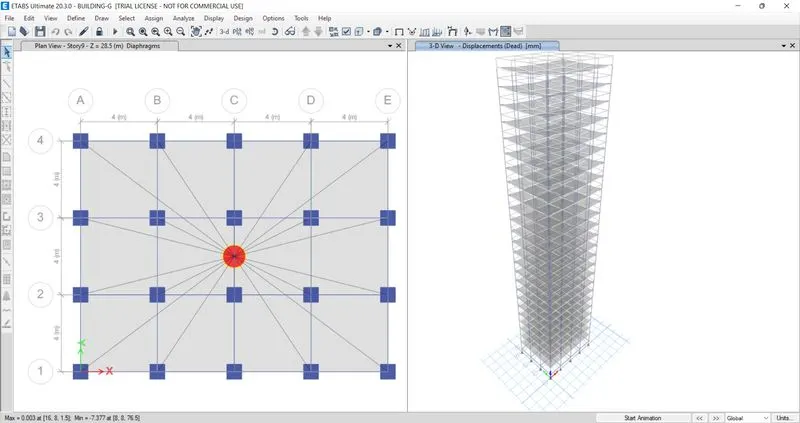
BUILDING-G
-BUILDING-F save it as BUILDING-G
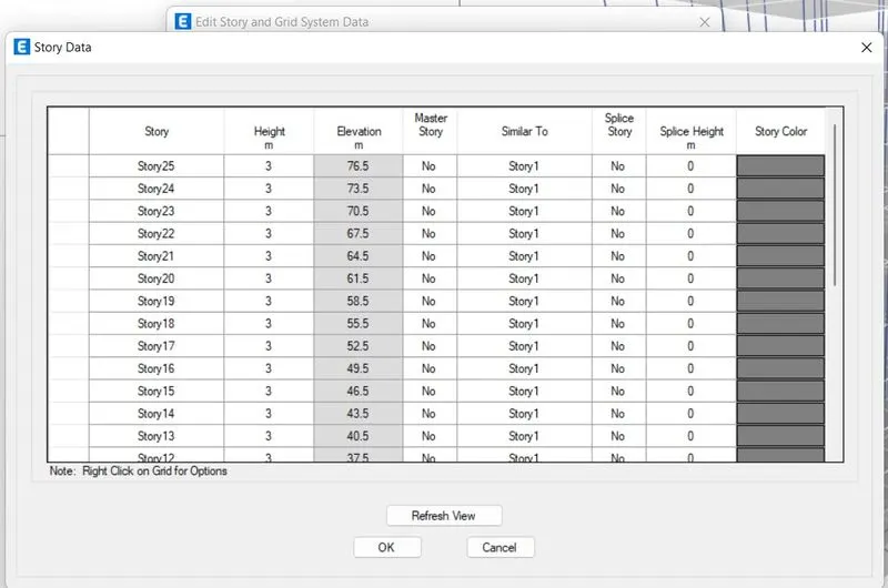
-Here add 15 more stories as building is 25 strory
-Go to Edit>Select Edit stories option>Select modify story>Add 5 story with keep existing height>Refresh view>Ok
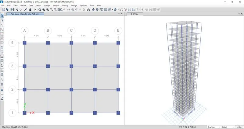
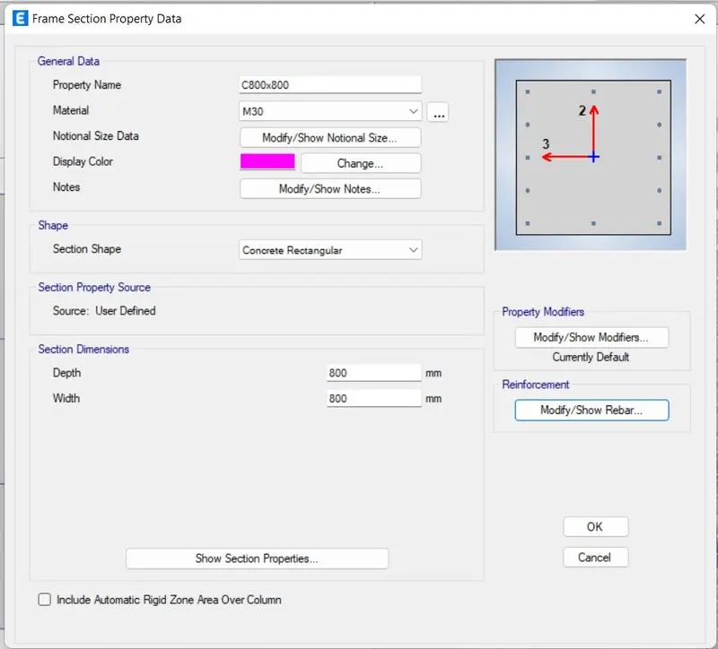
-Now add new column
-Go toDefine>Select section property>Select new property>Select rectangular shape>Add name C400x400, add grade 415
-Click on refinforcement modify>Select column>Select 415
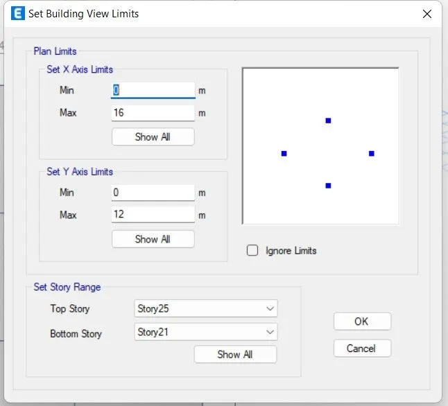
-Now hide beam and floor
-Go to View>Select set building view option>Set base as story as 21 and top story as 25
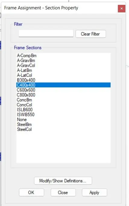
-Now select all coliumn present in this view
-Go to Assign>Select Frame>Select section property>Select column 400x400
-Go to View>Select set building view option>Set base as story as 11 and top story as 20
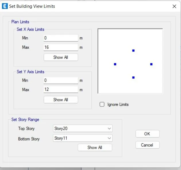
-Now select all coliumn present in this view
-Go to Assign>Select Frame>Select section property>Select column 600x600
-Go to View>Select set building view option>Set base as story as base and top story as 10
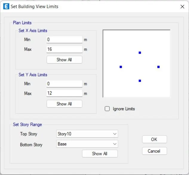
-Now select all coliumn present in this view
-Go to Assign>Select Frame>Select section property>Select column 800x800
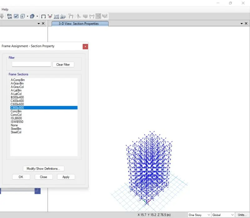
-Now set view as previous and unhide beam and floor
-Go to Select>Select Properties>Select slab section of 150
-Go to Assign>Select shell>Select Diaphgram
-Run Analysis
BUILDING-H
-BUILDING-G save it as BUILDING-H
-Here the only change is all columns of 25 story are same size
-Now hide beam and floor
-Go to View>Select set building view option>Set base as story as base and top story as 25
-Now select all coliumn present in this view
-Go to Assign>Select Frame>Select section property>Select column 800x800
-Now set view as previous and unhide beam and floor
-Go to Select>Select Properties>Select slab section of 150
-Go to Assign>Select shell>Select Diaphgram
-Run Analysis
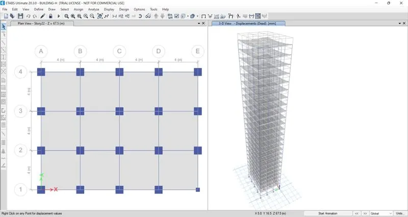
BUILDING-J
-BUILDING-H save it as a BUILDING-J
-Here imposed mass is 10% greater than BUILDING-H
-Go to Select>Select properties>Select slab>Select slab150
-Go to Assign>Select shell load>Select live change it 3.3
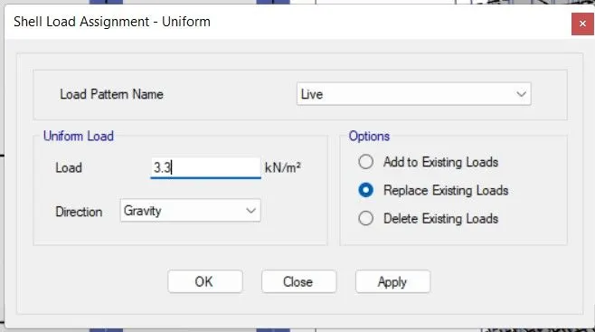
-Apply load
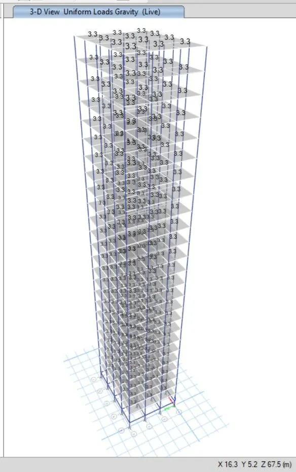
-Run Analysis
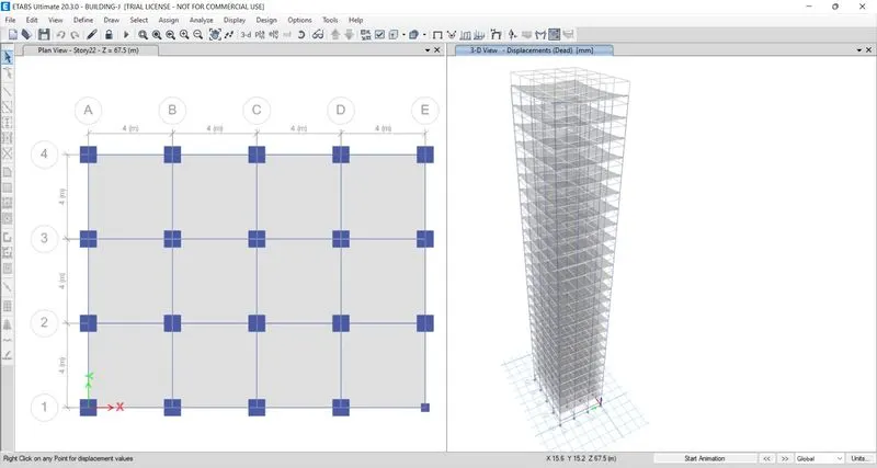
BUILDING-K
-BUILDING-J save it as a BUILDING-K
-Here imposed mass is 10% greater than BUILDING-H
-Go to Select>Select properties>Select slab>Select slab150
-Go to Assign>Select shell load>Select live change it 3.6
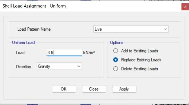
-Apply load
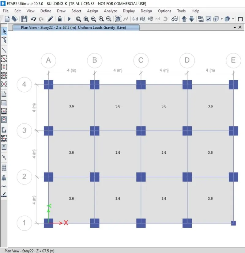
-Run Analysis
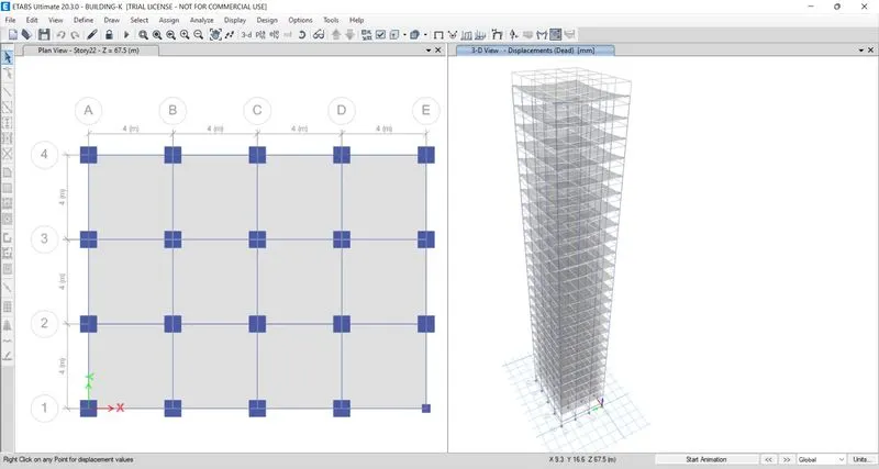
Result-
We created all the given 10 models in ETABS.
We noted down the Time periods of all the models.
We compared the Analysis results for each of the criteria.
Identified the reasons for the influences and reported in tabulation form.
Factors influencing the Natural Period of a building
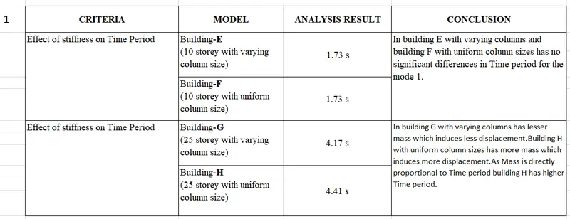
- Effect of stiffness on T:
- Compared fundamental natural periods of buildings E & F as well as G & H.
- We observed and noted down what could be the factors affecting for the differences in the Time period.
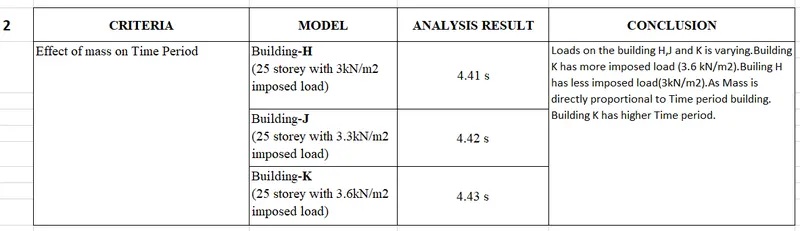
- Effect of mass on T:
- Compared fundamental natural periods of buildings H, J and K.
- We noted down observations about buildings become more flexible or stiff due to change in mass.
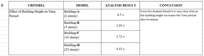
- Effect of Building Height on T:
- Compared fundamental natural periods of buildings A,B,F and H.
- We observed and noted How fundamental natural periods of Buildings A, B, F and H change with change in building height
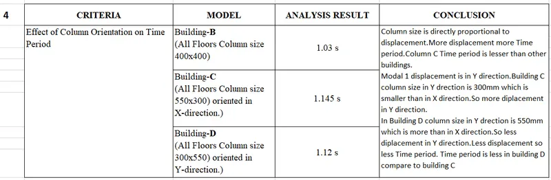
- Effect of Column Orientation on T:
- Compared fundamental natural periods of buildings B,C and D.
- We observed and drawn conclusion about change in the fundamental natural periods of Buildings B, C and D with change in column orientation
Factors influencing the Mode shape of oscillations
- Effect of Flexural Stiffness of Structural Elements on mode shapes:
- Compared fundamental mode shape of Building B in two situations when flexural stiffness of beams relative to that of adjoining columns is very small versus when it is large.

- Effect of Axial Stiffness of Vertical Members on mode shapes:
- Compared fundamental mode shape of Building H in two situations when axial cross-sectional area of columns is very small versus when it is large.

- Effect of Degree of Fixity at column bases on mode shape:
- Compared fundamental mode shape of Building B in two situations when base of columns is pinned versus when it is fixed.
