Project 1_Comparative study of different storey buildings for Seismic forces
AIM
Comparative study of different storey buildings for Seismic forces
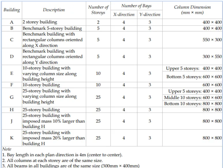
INTRODUCTION
ETABS is an engineering software that is used for multi-story building analysis and design. Modeling tools and templates, code-based load prescriptions, analysis methods and solution techniques, all coordinate with the grid-like geometry unique to this class of structure.
Here we are modeling and analyse different storey building using ETABS
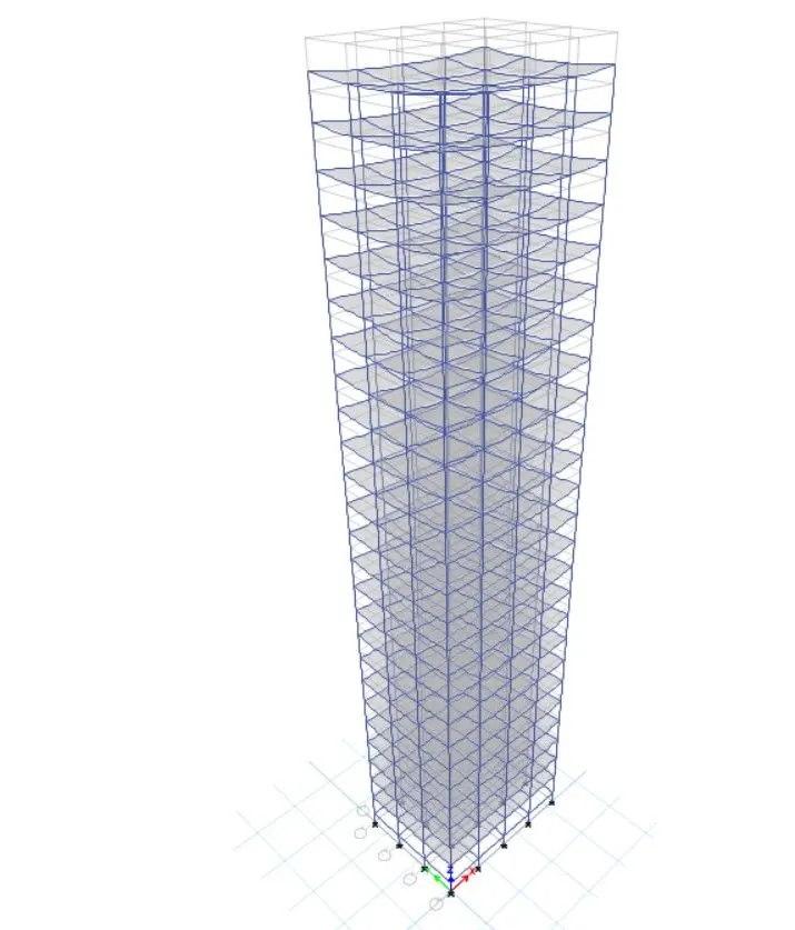
Here we are modelling 2,5,10 and 25 story building with different column sizes.The editing of the modelled building using editing options in the ETABS
We are finding
Factors influencing the dynamic characteristics of a building
Factors influencing the Natural Period of a building
Factors influencing the Mode shape of oscillations
PROCEDURE
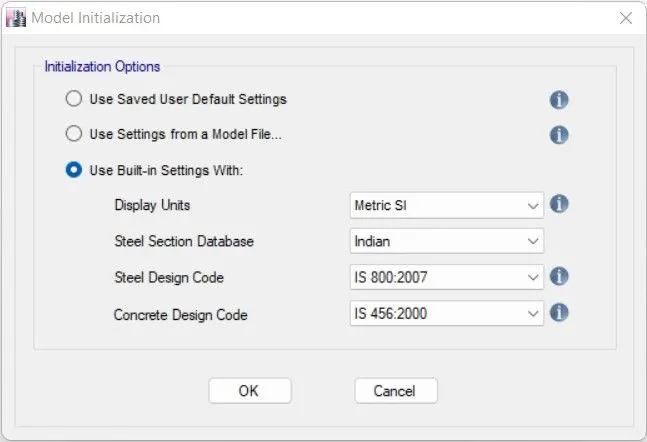
Step 1:Open ETABS software
Open a new model
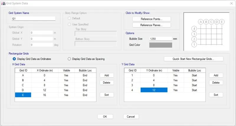
Step 2:Select Custom grid spacing
Select ‘edit grid data’
Step 3:Select story data
Select edit story data
Step 4:Select story 3, Delete the story
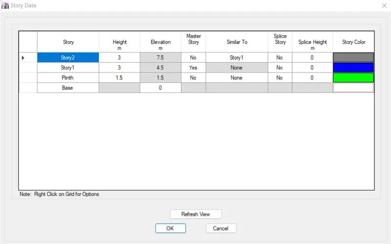
Step 5:Select story 1 make it master story
Make all other stories similar to story 1
Step 6:From define tab select material property
Add M30 concrete and HYSD415 rebar
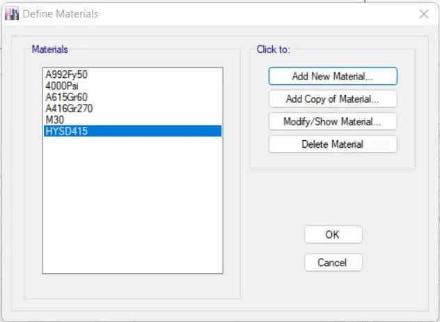
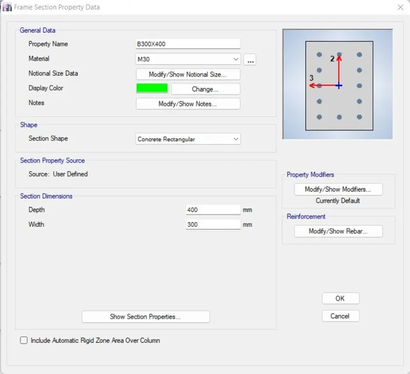
Step 7:From define tab select section properties
Then select Frame sections -Add new sections
Add columns and beam
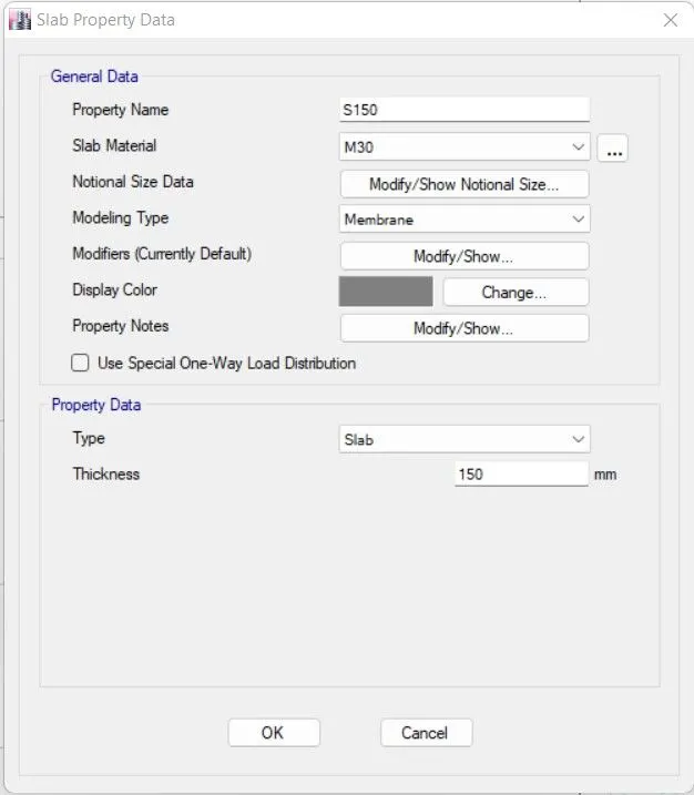
Step 8:From define tab select section properties
Select slab sections
Add new property
Add slab properties
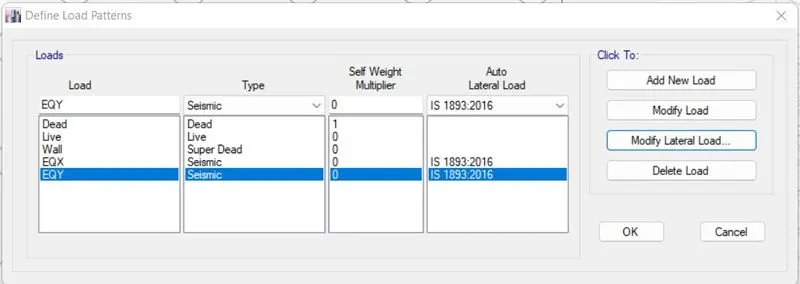
Step 9:Select define
Select load patterns
Add load patterns
Step 10:Select define
Select mass sources
Add mass and mass multipliers
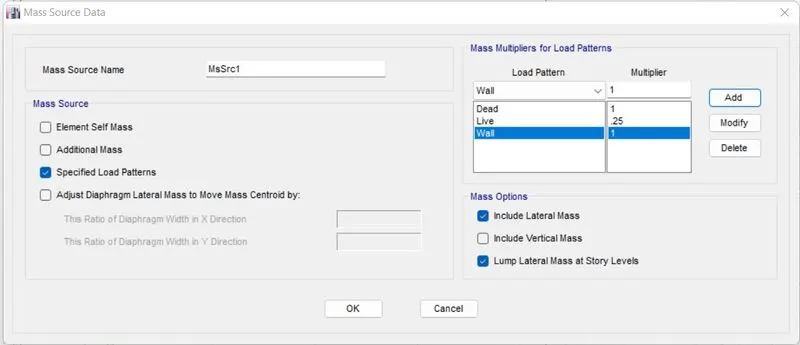
Step 11:From define select load cases
Step 12:From define select load combinations
Add load combinations
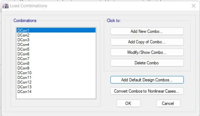
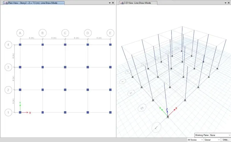
Step 13:Select quick draw columns
Select all stories
Select the column size
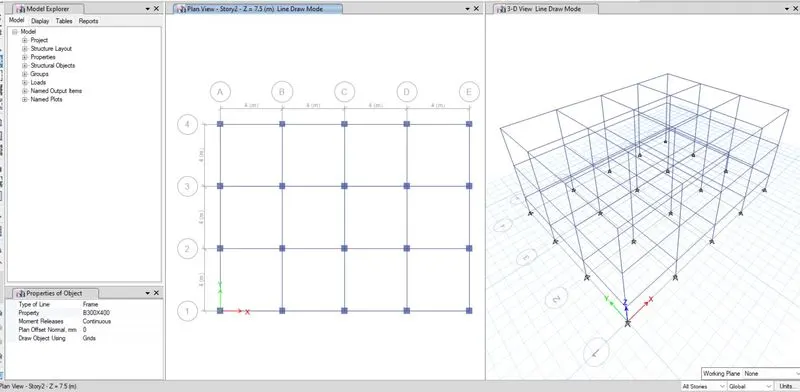
Step 14:Select quick draw beams
Select all stories
Select the beam size
Step 15:Select the master story(story 1)
Select similar story
Select Quick draw floor
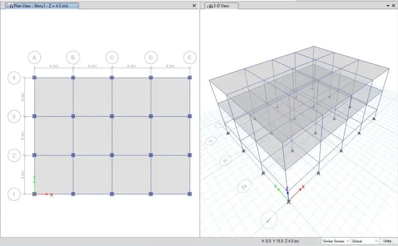
Step 16:From select option-properties-select beam
Select all beams

Step 17:From assign tab-select frame load-distributed
Assign load to beams
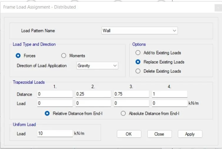
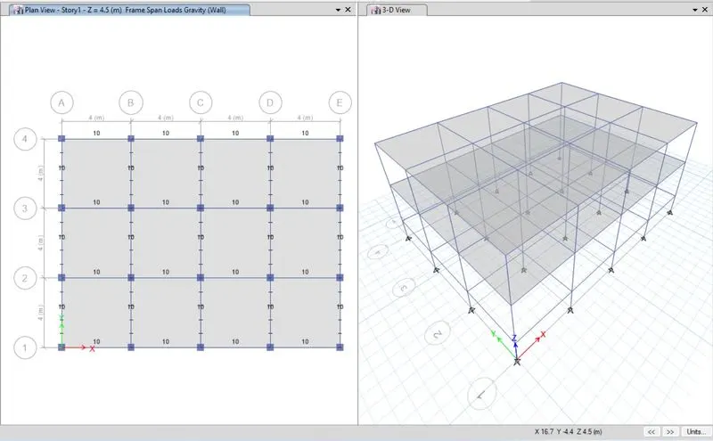
Step 18:Assign -select shell load -select uniform
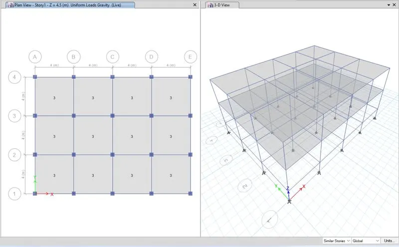
Step 19:Select all slabs
Assign-shell-Diaphragms
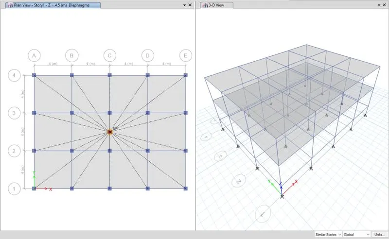
Step 20:Select ‘Run analysis’
Save it as model A
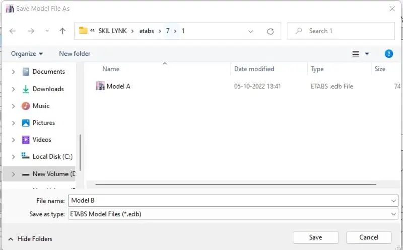
Step 21:Save the file as Model B
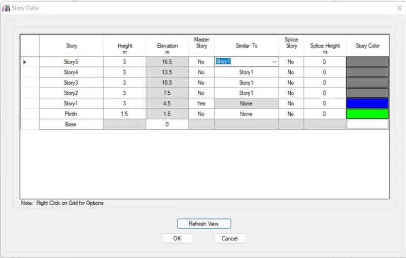
Step 22:From edit
Select edit stories and data
Click on modify
Modify the stories to 5 story
Step 23:Run analysis
Step 24:Save the file as Model C
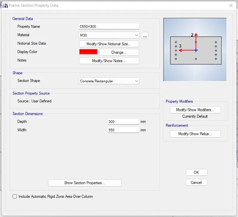
Click on define
Section properties -frame sections
Select column c400x400
Edit the column to c550x300
Step 25:Select the column
Assign -frame-local axes
Set angle to 90 degree
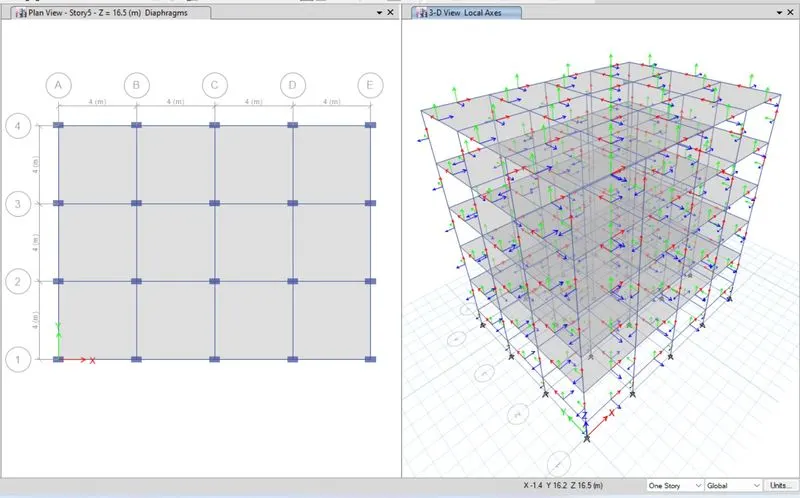
Step 26:Run analysis
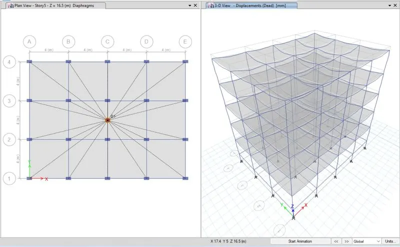
Step 27:Save the file to model D
Step 28:Select the column
Assign -frame-local axes
Set angle to 0 degree
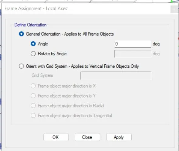
Step 29:Run analysis
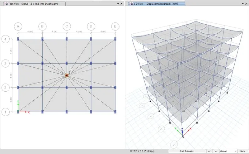
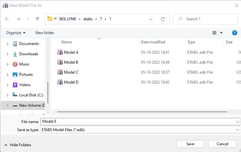
Step 30:Save the file as model E
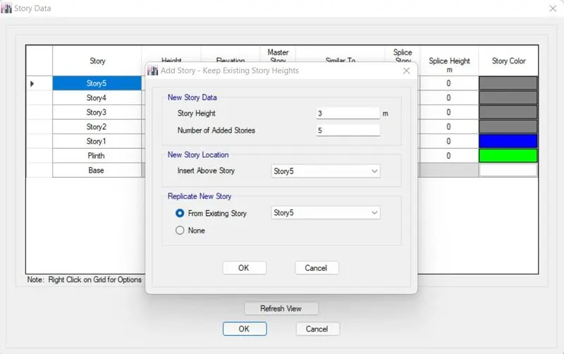
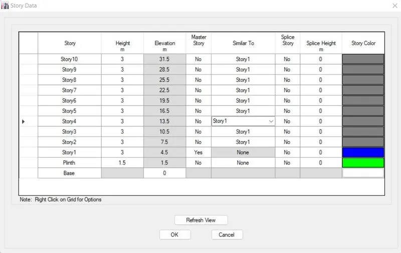
Step 31:From edit
Select edit stories and data
Click on modify
Modify the stories to 10 story
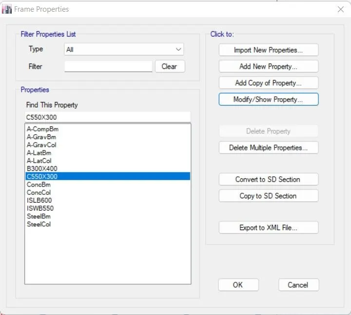
Step 32:Click on define
Section properties -frame sections
Select column C550x300
Edit the column to C600x60
Add 400x400 column
Step 33:Click on set display option
Unselect beam and floors
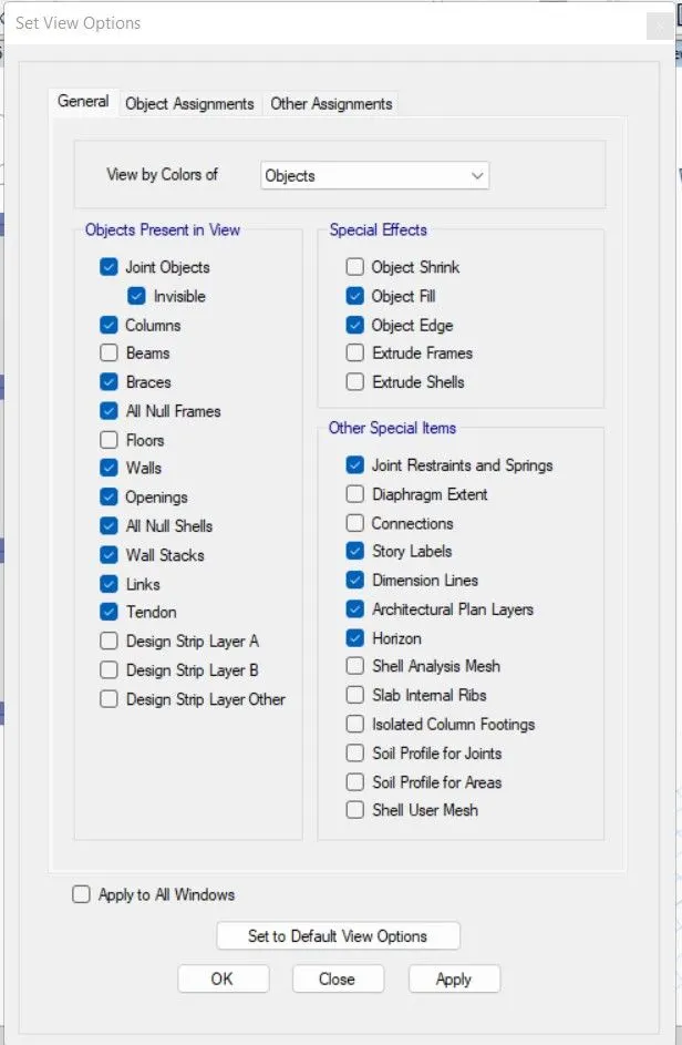
Step 34:Select the view
Select set building view
Select bottom story as story 6
Step 35:Select all columns in the view
assign -Frame-section property
Select 400x400 column
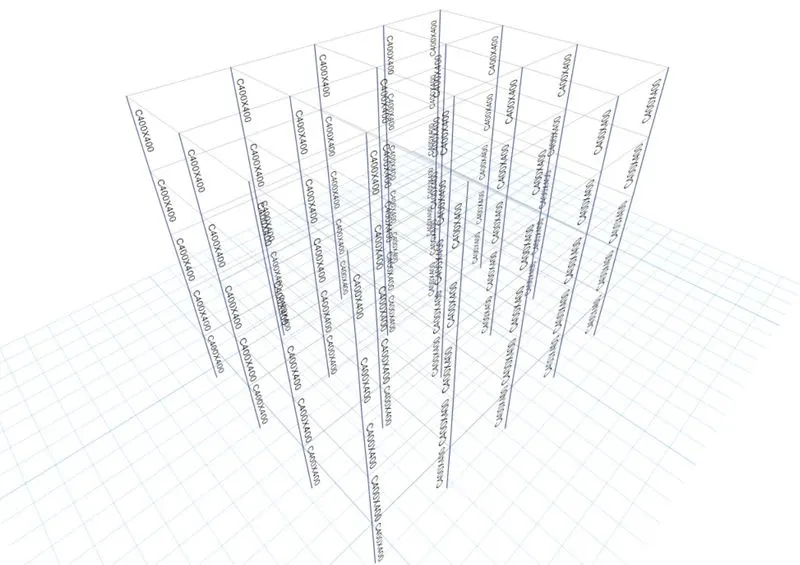
Select the view
Select set building view
Select bottom story as base
Step 36:Run analysis
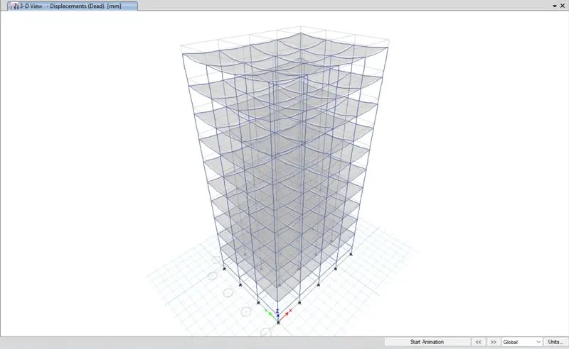
Step 37:Save the file as model F
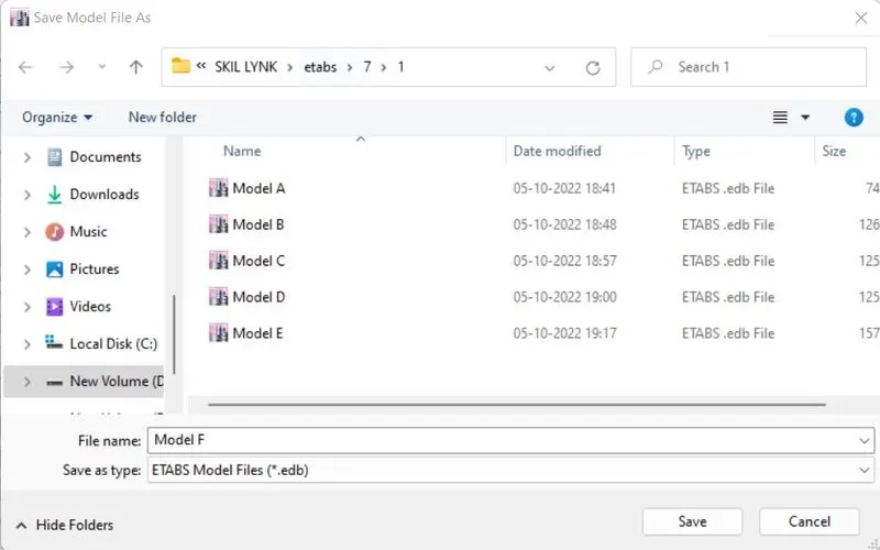
Step 38:Click on set display option
Unselect beam and floors
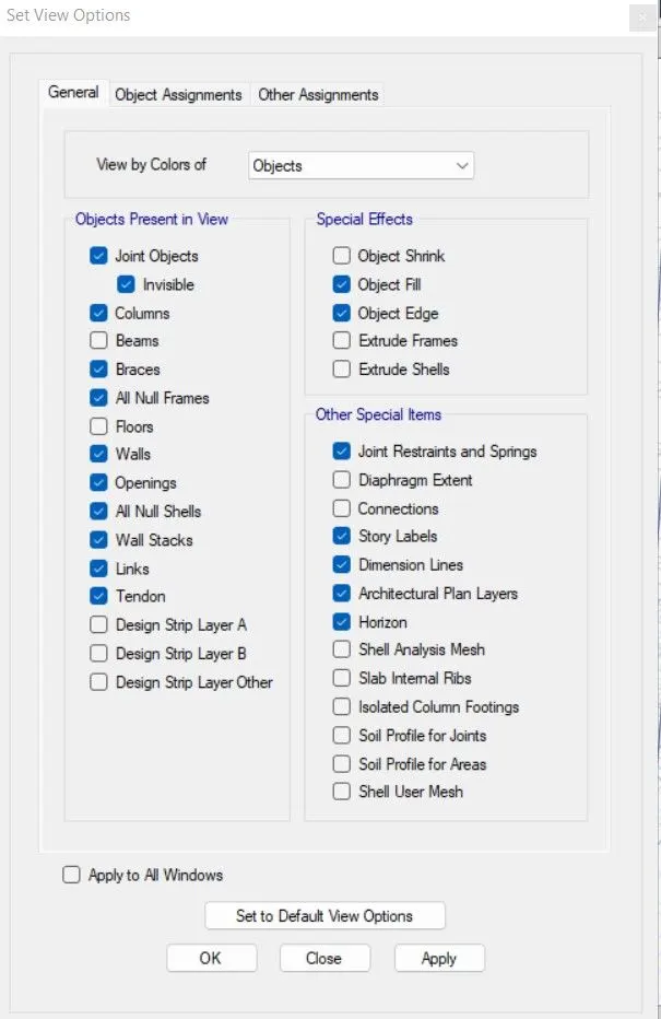
Step 39:Select the view
Select set building view
Select bottom story as story 6
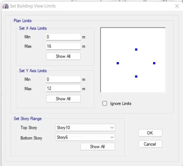
Step 40:Select all columns in the view
Assign -Frame-section property
Select 600 x 600 column
Step 41:Select the view
Select set building view
Select bottom story as base
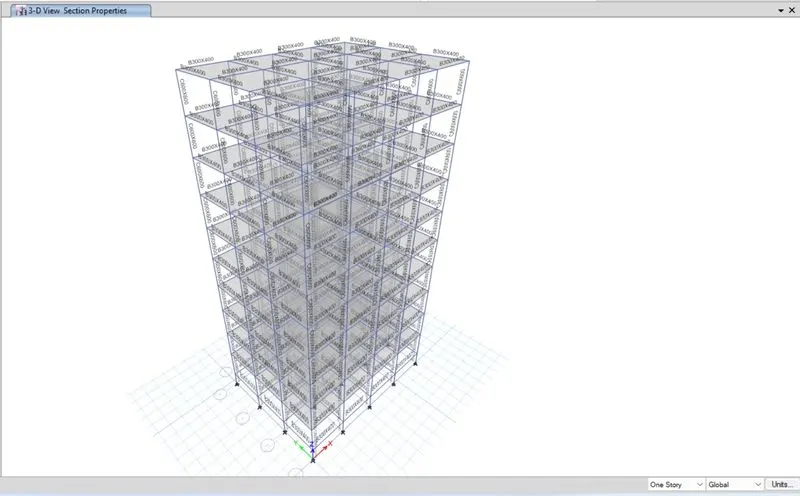
Step 42:Run analysis
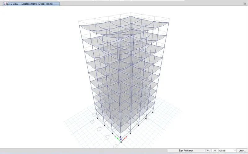
Step 43:Save the file as model G
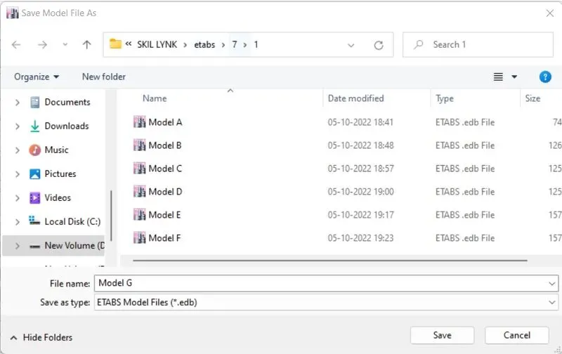
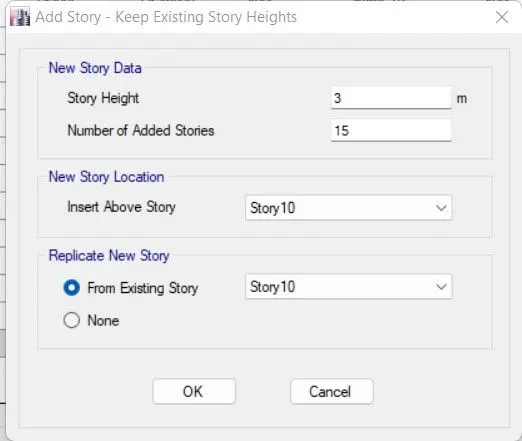
Step 44:From edit
Select edit stories and data
Click on modify
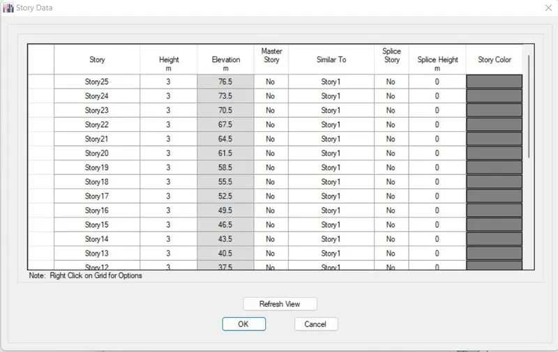
Modify the stories to 25 story
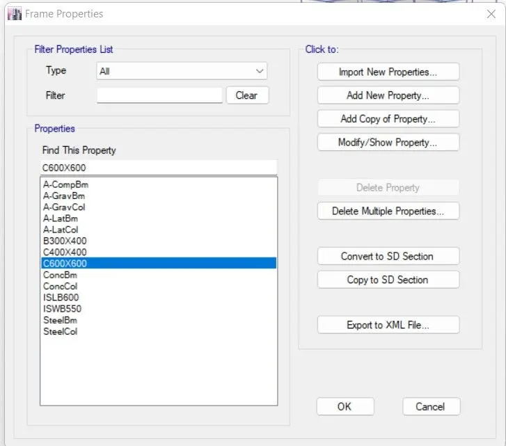
Step 45:Click on define
Section properties -frame sections
Select column C600x600
Edit the column to C800x800
Add 600x600 column
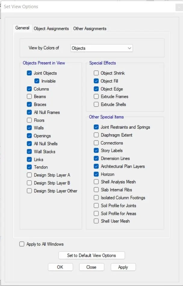
Step 46:Click on set display option
Unselect beam and floors
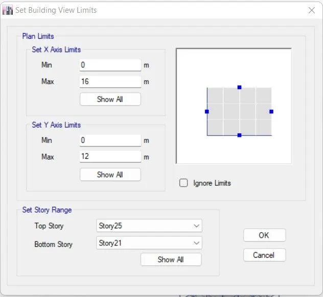
Step 47:Select the view
Select set building view
Select Top story as 25
Bottom story 21
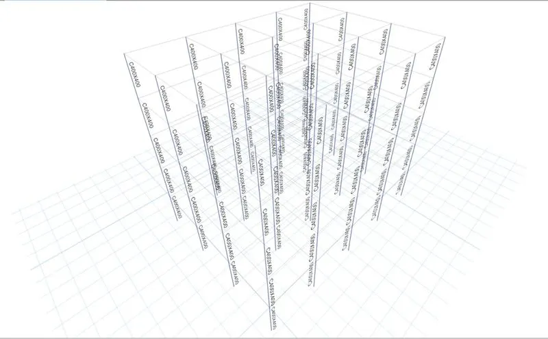
Step 48:Select all columns in the view
Assign -Frame-section property
Select 400 x 400 column
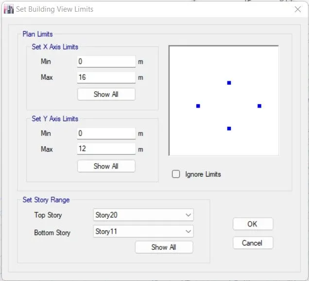
Step 49:Select the view
Select set building view
Select Top story as 20
Bottom story 11
Step 50:Select all columns in the view
Assign -Frame-section property
Select 600 x 600 column
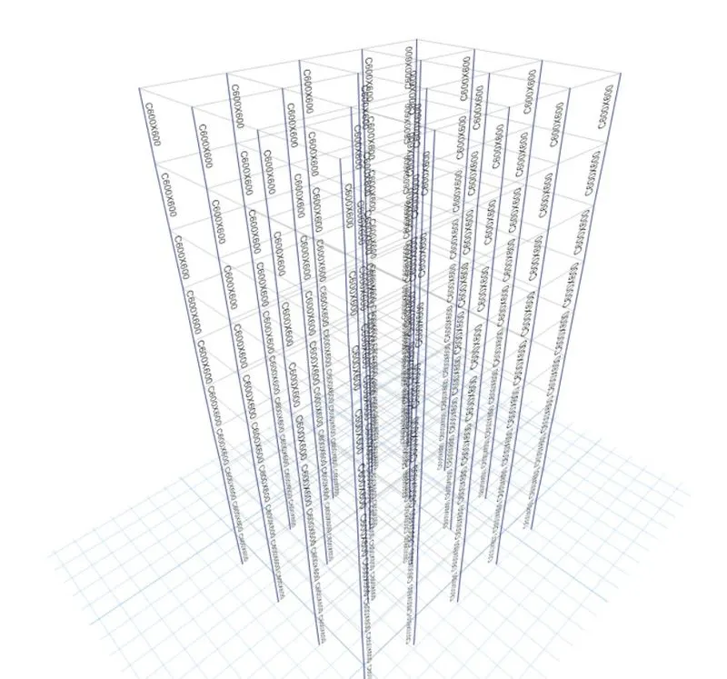
Step 51:Run analysis
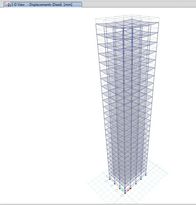
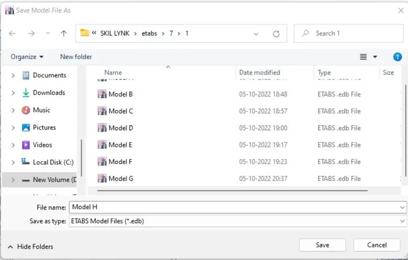
Step 52:Save the file as model H
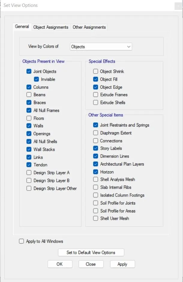
Step 53:Click on set display option
Unselect beam and floors
Step 54:Select all columns
Assign -Frame-section property
Select 800 x 800 column
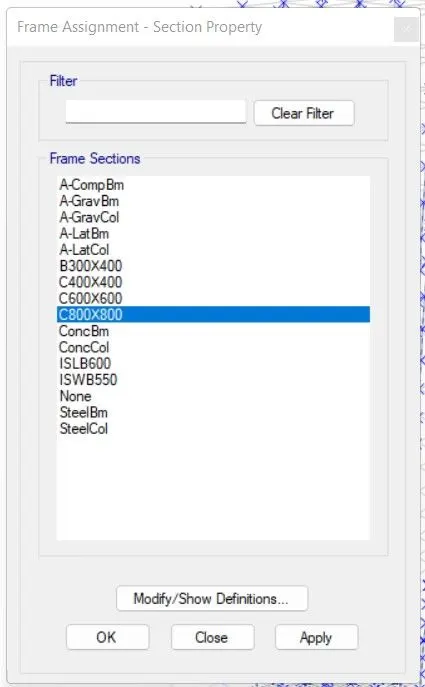
Step 55:Run Analysis
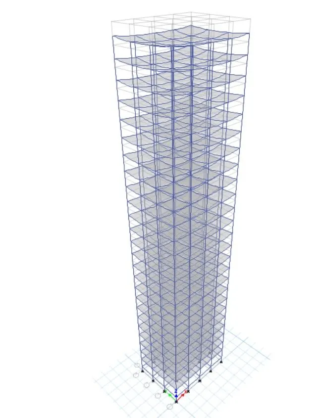
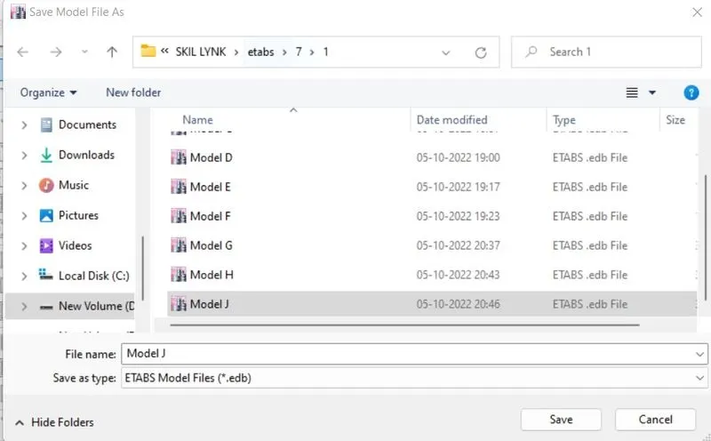
Step 56:Save the file as model J
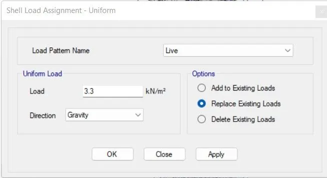
Step 57::Assign -select shell load -select uniform
Select Live load
Add the value as 3.3
Step 58:Run Analysis
Step 59:Save the file as model K
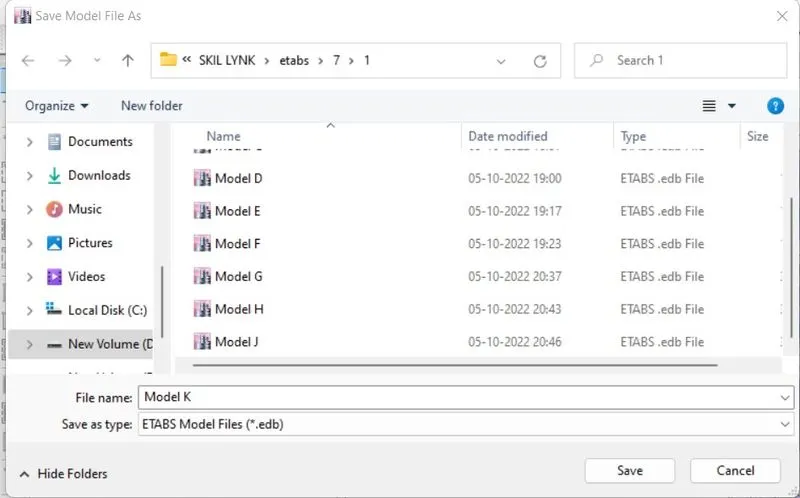
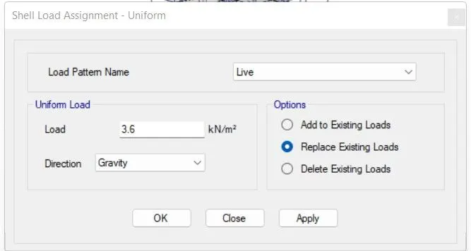
Step 60::Assign -select shell load -select uniform
Select Live load
Add the value as 3.6
Step 61:Run Analysis
RESULTS
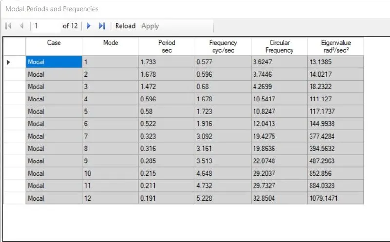
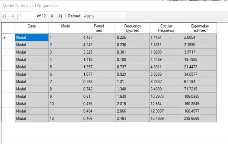
1)Model period and frequencies of
Building E,F,G,H
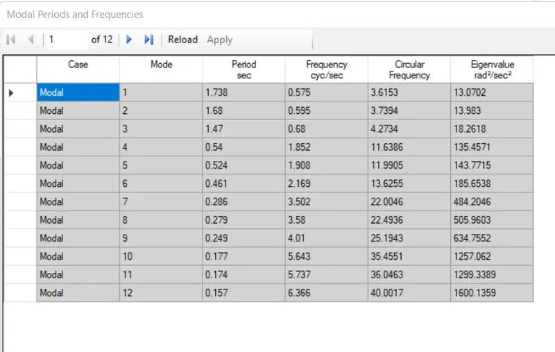
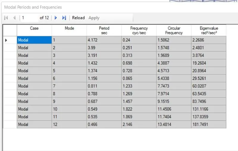
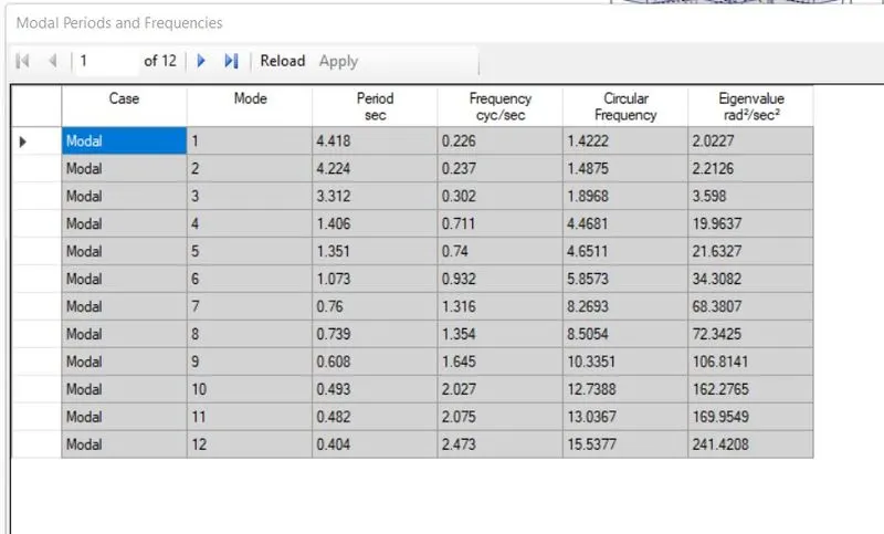
|
Criteria |
Model |
Analysis result |
Conclusion |
|
Effect of stiffness on time period |
Building-E (with varying column size) |
1.73 s. |
Here the uniform column size and varing column size have no significant difference in their fundamental time period But for higher stories varing column size is more stable than uniform column size |
|
Building-F (10 story with uniform column size) |
1.73 s. |
||
|
Building-G (25 story with varying column size) |
4.17 s. |
||
|
Building-H (25 story with uniform column size) |
4.41 s. |
2)Model period and frequencies of
Building H,J,K
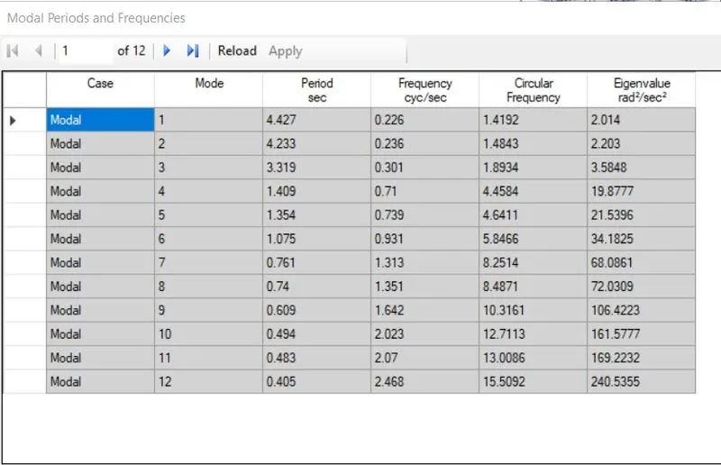
|
Criteria |
Model |
Analysis result |
Conclusion |
|
Effect of mass on time period |
Building-H (25 story with uniform 3.0kN/m2 imposed load) |
4.41 s. |
There is no significant change in time period.For change in the imposed load, but mass dirctly propotional to the lateral force |
|
Building-J (25 story with uniform 3.3kN/m2 imposed load) |
4.42 s. |
||
|
Building-K (25 story with uniform 3.6kN/m2 imposed load) |
4.43 s. |
3)
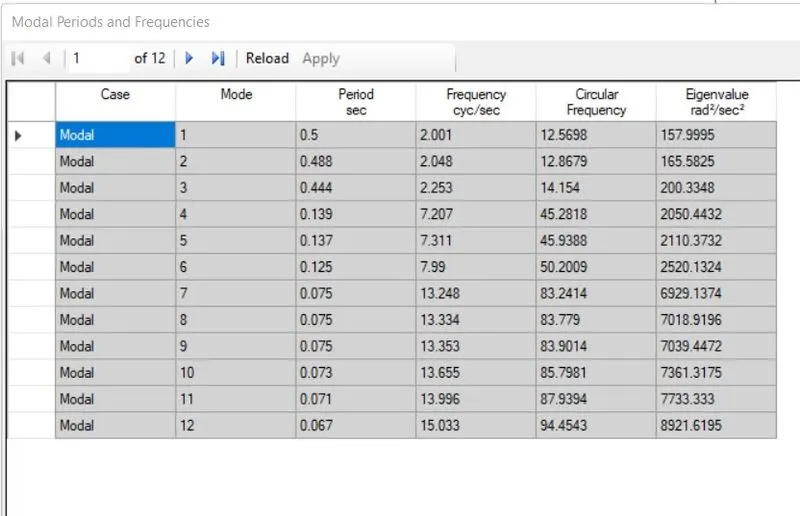
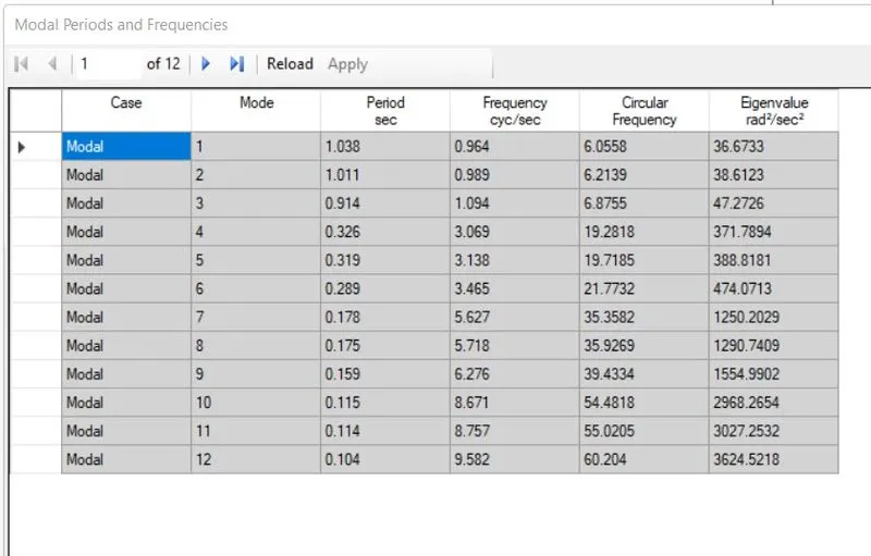
Model period and frequencies of
Building A,B,F,H
|
Criteria |
Model |
Analysis result |
Conclusion |
|
Effect of building height on time period |
Building-A (2 story) |
0.50 s. |
It is clear that time period varying according to the height of the building. The time period is directly proportional to the height of the building. |
|
Building-B (5 story) |
1.03 s. |
||
|
Building-F (10 story) |
1.73 s. |
||
|
Building-H (25 story) |
4.41 s. |
4)
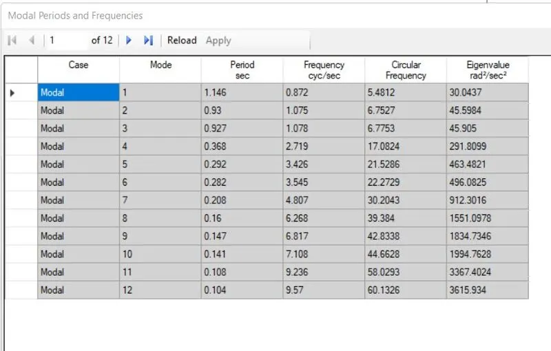
Model period and frequencies of
Building B,C,D
|
Criteria |
Model |
Analysis result |
Conclusion |
|
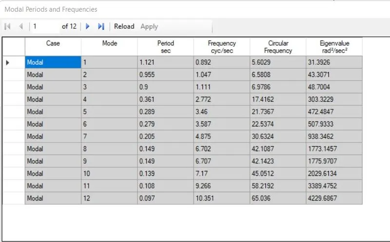
Effect of column orientation on time period |
Building-B (All floors column size C400X400) |
1.03 s. |
The deflection of building D will be higher in X direction than Y The deflection of building C will be higher in Y direction than X |
|
Building-C (All floors column size C550X300 while oriented in X-direction. |
1.14 s. |
||
|
Building-D (All floors column size C300X550 while oriented in Y-direction. |
1.12 s. |
5)
Model period and frequencies of
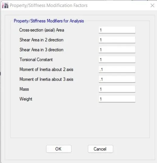
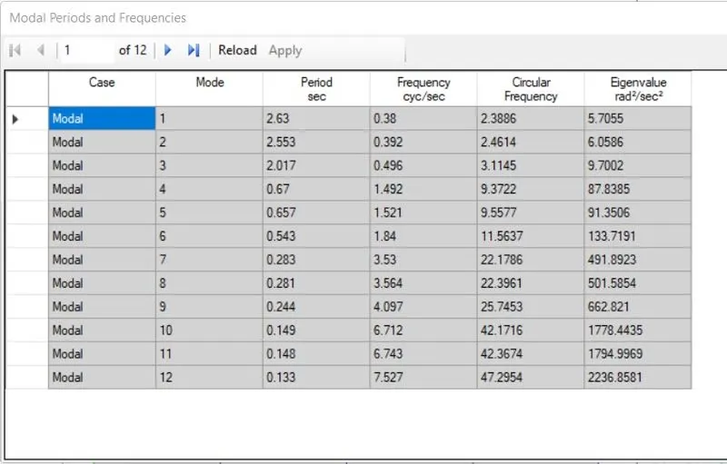
Building B and Building B with Flexural stiffness of beams close to nil (Zero inertia)
Select Define-section properties-Frame sections
Select the beam section and modify the section
|
Criteria |
Model |
Case |
Analysis result |
Conclusion |
|
Effect of Flexural Stiffness of structural elements on mode shapes. |
Building-B |
Flexural stiffness of beams close to nil (Zero inertia) |
2.63 s. |
It is clear that Flexural stiffness play a significant role in time period,as it changes the value is doubled |
|
Full Flexural stiffness of beams (regular) |
1.03 s. |
6)
Model period and frequencies of
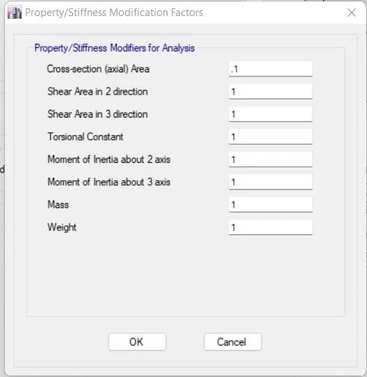
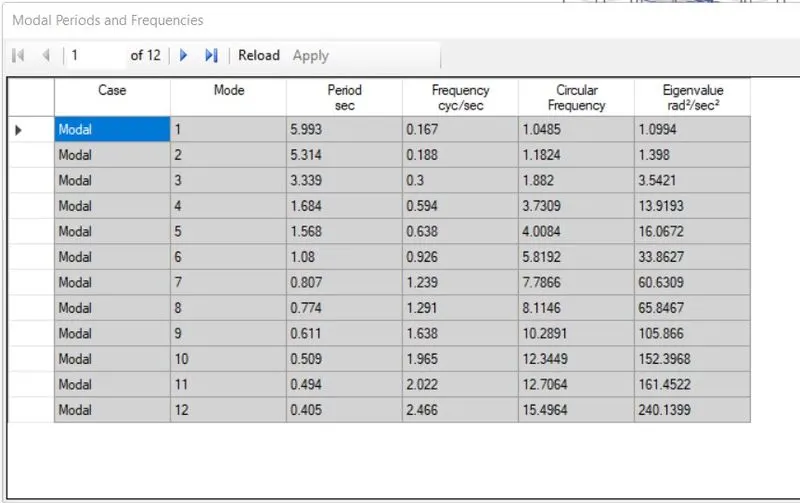
Building H and Building H with Axial cross section for columns is close to nil (Zero axial area)
Select Define-section properties-Frame sections
Select the beam section and modify the section
|
Criteria |
Model |
Case |
Analysis result |
Conclusion |
|
Effect of Axial Stiffness of vertical members on mode shapes. |
Building-H |
Axial cross section for columns is close to nil (Zero axial area) |
5.99 s. |
It is significant that the Axial Stiffness have a vital role in the time period of the building |
|
Full axial cross section for columns (Regular) |
4.41 s. |
7)
Model period and frequencies of
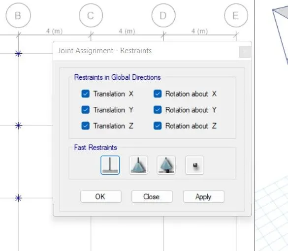
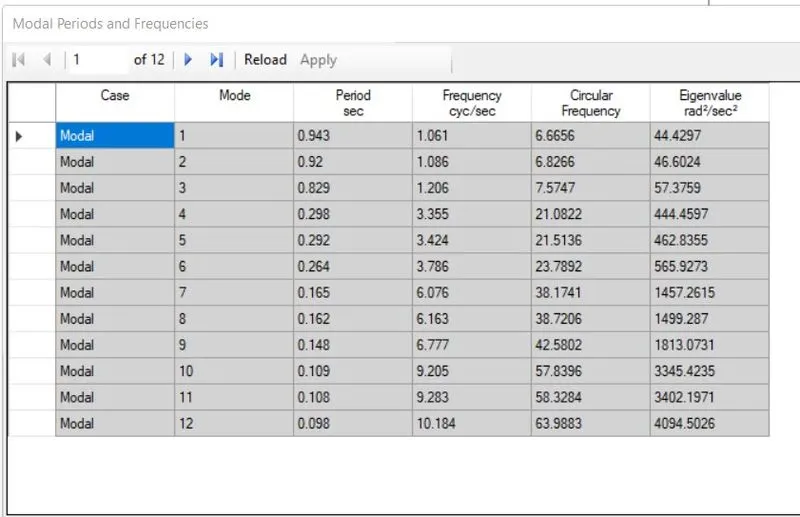
Building B and Building B with Fixed column support
Go to plan view -Select Base
Select the all the joint-Select Assign
Select joint -Select Restraints
select the fixed-Then Analyse
|
Criteria |
Model |
Case |
Analysis result |
Conclusion |
|
Effect of degree of fixity at column base on mode shape. |
Building-B |
Column support pinned (regular) |
1.03 s. |
The time period have significant change in pinned and fixed conditions The more the fixity of the column the lesser it gets difflected |
|
Column support Fixed. |
0.943 s. |