Project 1 : CFD Meshing for Tesla Cyber Truck
Aim:
To check and solve all geometrical errors and assign appropriate PIDs. Perform meshing with the suitable Target length and element Quality criteria.
Objective:
Target lengths for the different parts of a model can be decided by your own. Finer mesh will give good results and will compromise with the longer processing time.
To Identifying & clean-up all the topological errors in the given Tesla Cyber Truck Car model.
To create a surface mesh.
To Create a wind tunnel around Tesla Cyber Truck Car.
To create a volumetric mesh to perform an external flow CFD analysis simulation.
Step 1:
First step we can start with the topo clean-up by removing the single and unnecessary triple cons. We should click on the topo and box select the entire to identify
or joins any unjointed single cons or triple cons so that we can identify the required clean-up.
Here, the main aim is to create whole car inside part as one as one volume, here tyres are inserted into the body but not attached.
As we seen that the given geometry has several topological errors, missing faces which are indicated by single cons & triple cons, but for the CFD analysis only the double cons
are preferred not even the triple cons are acceptable because it may lead to forming a local volume over there.
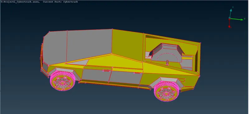
We have to check what are all the errors are there in our geometry by using geometry check-up. It will show lot of single, triple, convex, concave, cons.
we should clear this kind of errors then only we can move meshing part. NOT option is used to hide the surface and easily to separate the required surface.
Using single, double, triple con tools enable is easily identify the errors.
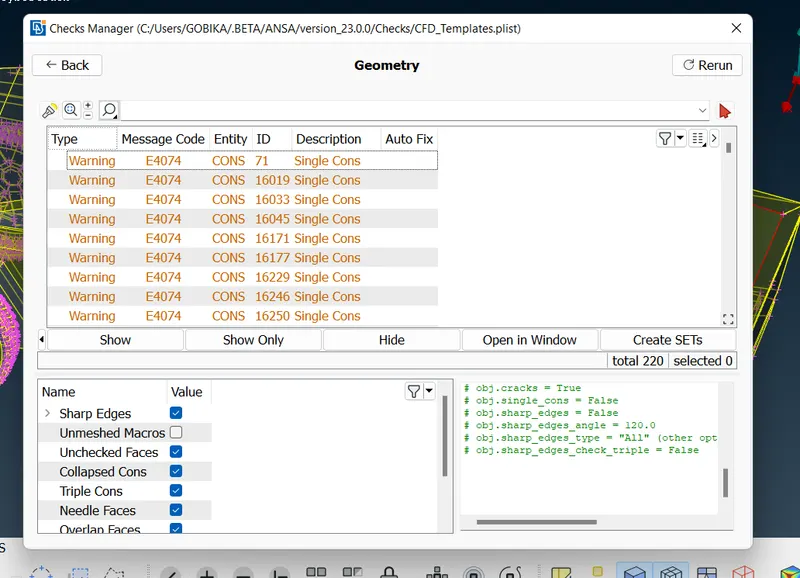
Here, we can go with two approaches either we can delete the common extra part and perform topo and make the whole cars and tyres as one volume or we can delete the
common part and close the holes such that only car forms one volume and as tyres are not attached, then each of them forms one volume means 4 tyres 4 volumes.
So, we delete all other volumes and keep the final volume as we ae doing external flow analysis. Initially, there were many errors, each of them should be rectified systematically by
one after other.
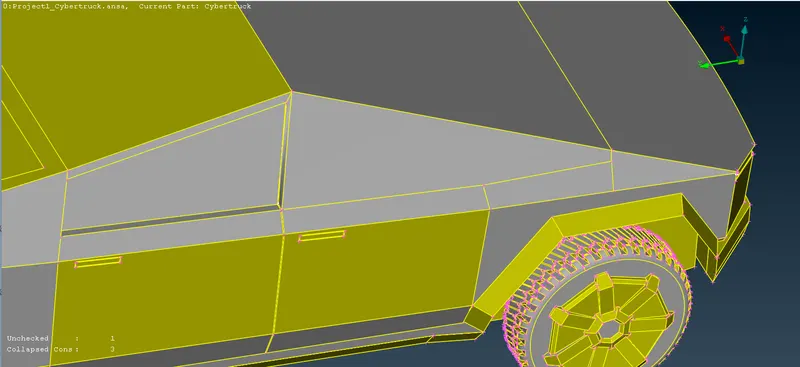
Here, also we are much concerned about outside features of the car and not about inside features. We, have to modify all the features such that we get whole car inside part as one volume.
So, to have the whole model as single volume we should have only double cons and even with double cons we should not have a feature closed on all sides, it may lead to form a separate
local volume over there
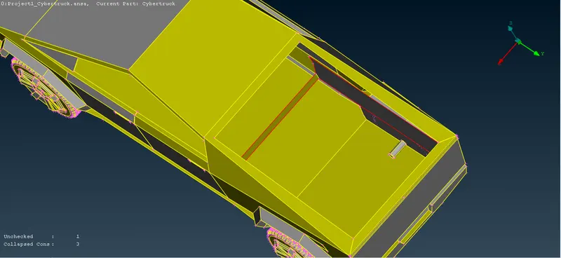
Also, when you find any small surface delete it and its neighbour surface and create a large surface such that we don’t have any quality criteria error while meshing.
So, we will delete the surfaces which are not necessary and causing an error or leading to cause a local volume. The topo clean-up process we cleared the errors almost next step
we should check the geometry check-up.
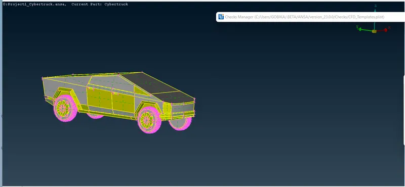
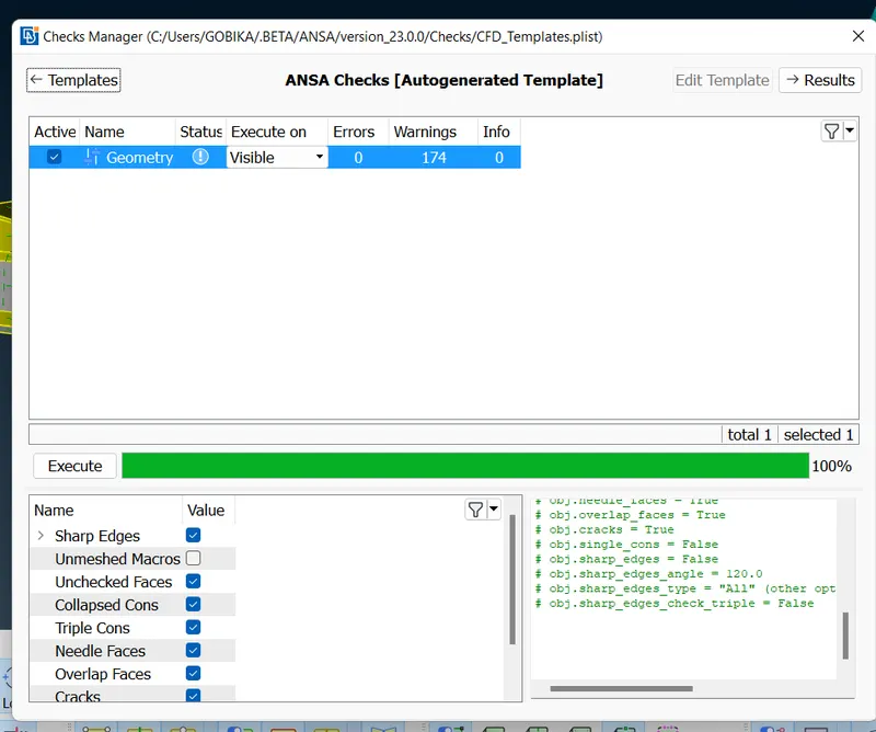
After topo clean-up we should check the geometry check-up. The geometry check-up shows the zero errors and 174 warnings. warning is not an issues so we can move the
next meshing process.
Step 2:
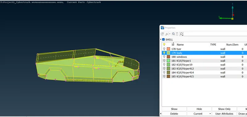
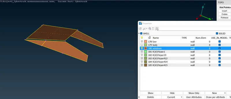
Before meshing process, we should assign the PID'S by using PID manager. We have to delete the unwanted PID'S and we should create the three PID's there are body,
rims and tyres, windows. Totally we have to assign the three PID's. And the we have to apply the particular parts.
Create NEW - SHELL PROPERTY - NAME - APPLY this is the step by step proceger to create PID'S
Step 3:
Next step we have to go mesh and choose target length, quality criteria and perimeters to smoothen the sharp curves of the car and give it a fine look. After that we have to
create wind tunnel and then we should generate the mesh for wind tunnel.
In this project we have to assign the target length Rims and Tyre = 2mm, Body = 3mm, Windows = 4mm
Meshing parameter, we should give 2mm for tyres and then quality criteria min length is 1mm and max length is 3mm for tyres. After that
we should give Mesh - length - perimeter - 2mm - macros - 2mm - mesh generation - shell mesh These all are the step-by-step procedures.
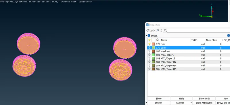
Meshing parameter, we should give 3mm for tyres and then quality criteria min length is 1mm and max length is 5mm for tyres.
After that we should give Mesh - length - perimeter - 3mm - macros - 3mm - mesh generation - shell mesh These all are the step-by-step procedures.
As well as we should give the windows target length is 4 mm the same procedure is follow for windows. After that
we should give Mesh - length - perimeter - 4mm - macros - 4mm - mesh generation - shell mesh These all are the step-by-step procedures for windows.
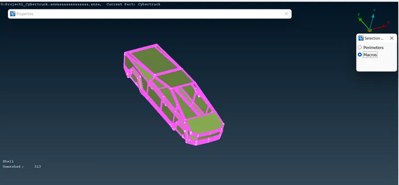
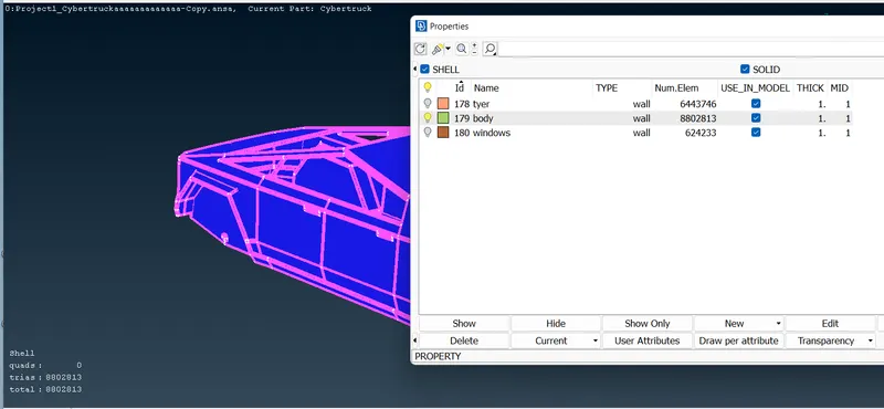
Each and every mesh process we should freeze the mesh because we assigned the difference mesh length so if we not freeze the mesh and while unhide the parts the mesh
will gone the join part. So the freeze option is used to freeze the mesh for separate part. And the below image is identify the three PID's.
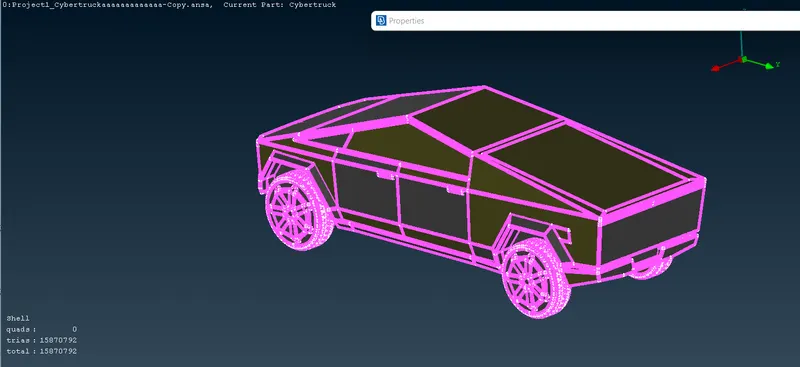
Below the image is represent the final mesh generation process.
Step 4:
After completing the meshing process the next process is to create wind tunnel.
Create the first point as reference to make sure that ground is lower than the tyre. To create a point below tyre surface, select RELATIVE option.
(TOPO DECK - POINTS - RELATIVE). Give a distance of 650 mm in negative Z direction.
Distance from front of the car to rear of the car = x = 6000 mm.
flow domain length height width
flow domain dimensions 66000*12800*7500
car dimensions 6000*3200*2100
These all are the wind tunnel parameters
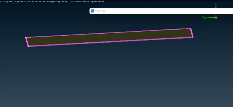
Bottom Wall = 50 mm.
Top Wall = 200 mm.
For side, inlet and outlet, we will be using variable meshing along the vertical length.
select SPACING option. (MESH DECK - PERIMETERS - SPACING).
Spacing input we should give factor value 1.1. Dstart 50mm, Dlimit 100mm.
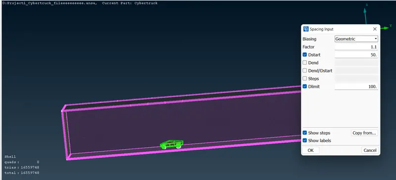
Once we create the wind tunnel after that we should assign the PID'S finally the total number of PID'S are 8.
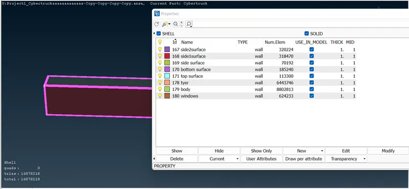
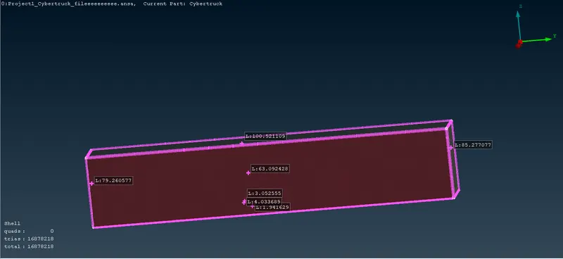
Finally, we created the wind tunnel after that we have to save the measurements for required parts.
Final look of the wind tunnel is given below.
Final Outcomes:
Topo clean-up the geometry using different tools.
Assigned respective PIDs.
Performed part wise meshing.
Creation of wind tunnel and its meshing.
Conclusion:
Finally, we completed the topo clean-up after that completed the meshing process and finally we created
the wind tunnel and wind tunnel meshing creation.
Drive link: https://drive.google.com/file/d/1ovqvgjEmMXU_SSB5SEmUb0iGn2AUPdP8/view?usp=sharing