CFD Meshing for Tesla Cyber Truck
OBJECTIVE:
The objective of this project is to do a basic geometric check and the do a Surface & Volumetric mesh using ANSA, on the given Tesla Cybertruck model.
TOOLS Used:
- Checks:
Checks is basically used to checks the errors in the model.
Tools used under Checks:
Checks manager`rarr`Geometry checks`rarr`Execute.
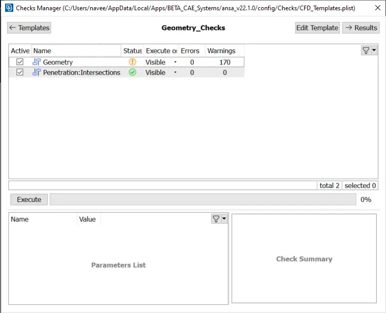
By clicking checks command a new pop up will appear, in that by clicking checks manager we can get a pop up window with diiferent types of checks that can be performed. In that by clicking Geometry_Checks and from the obtained pop up we can select geometry and penatration command and then execute. Then ansa will do the geometry check and will give the results.
- Topo:
Faces:
Delete(to delete the unwanted faces). New (to create the required faces).Intersect(to intersect required cons with faces).
Curves:
Create (to create required curves). Delete(to delete unwanted curves or unwanted created curves)
Hot Points:
Insert (to insert hot points if needed) Intersect (to intersect created curves & faces).Delete(to delete unrequired Hot points). Project(to project an exisiting hot point on a con)
CONS:
Fill hole(to fill holes).Project(to project cons on faces)
Points:
New(To create new points), Relative(To create a relative point to a exisiting Nodes or points).
- PID Selection:
To define PID's specifically.
PID(from the lists from the top)`rarr`create New PID`rarr`name the PID`rarr`Apply(select the particular PID).
- Utilities:
TransformCopy(copy the surface to be transformed)Entities(select the entities to be copied)Symmetry(to do symmetry of the entities)Mirror 3 points plane(select the points to symmetry the selected entities).
Measure`rarr`Nodes(to measure the nodes)or Cons(to measure the cons).
Compress(to compress the unwantedly created PID's).
Mesh Parameters(to define the required mesh parameters).
Quality Criteria(to define the quality of the required mesh).
- MESH:
In this we are going to use CFD mesh.
Perimetes`rarr`Spacing`rarr`Auto CFD`rarr`Perimeters(select the perimeters)`rarr`Macros(Select the macros).
Mesh generations`rarr`CFD`rarr`Visible(to mesh all the models that are visible) or Select(to mesh a particular PID).
Shell Mesh:
Recontruct(to reconstruct the created mesh to avoid off elements).Smooth(to smooth the PID's)
- Volume Mesh:
Volume`rarr`Define`rarr`Whole db(select the required volume to be meshed i.e. the volume between the outer part of the car body and the inner part of the wind tunnel).
Procedure:
Given Model,
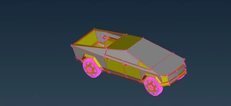
We can see that there are a lot of single cons in our model, we can just do a TOPO to clean them.
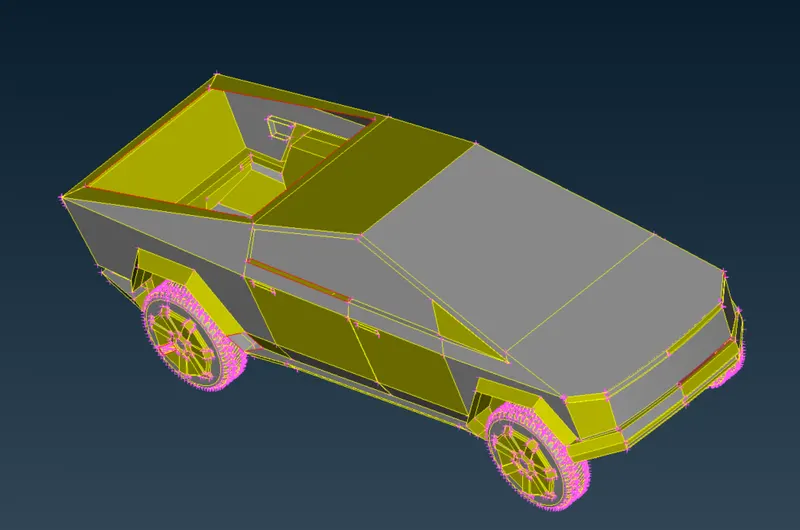
After TOPO some of the single cons are changed into double cons,
We can cut the model in half to performe geometry checks in a simple manner then we can symmetry it since the other half is exactly the same.
Selecting the part that we are about to delete,
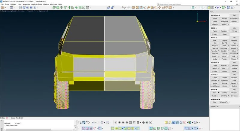
Seleted part deleted,
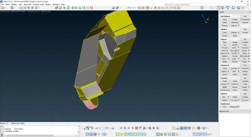
Then lets do a geometry check,
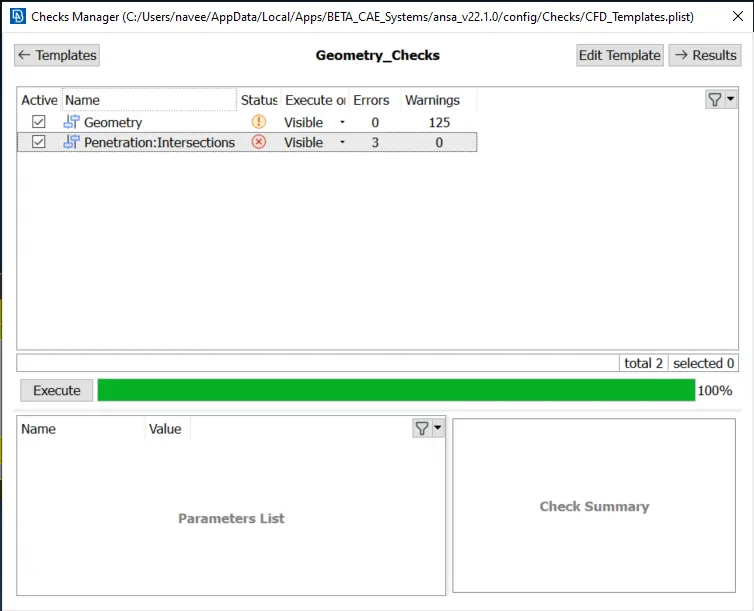
We can see there are some penetration issues, we have to try and solve those issues. After checking and performing topo-clean up for the entire half car model. We should do a final geometry checks to find if there are any remaning small cracks are unchecked faces which is not good for the geometry,
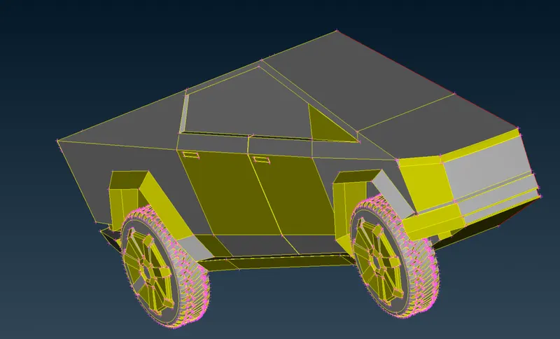
Model after geometry clean up,
Geometry check to find any remaining errors,
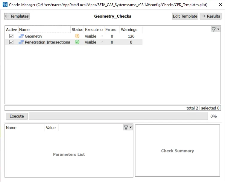
As we can see there are no errors remaning, so we can go with assining the PID's and then meshing.
Assining PID's:
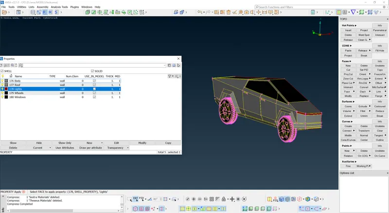
MESHING:
Here we perform all the three tasks ,defining the element size or length and setting the mesh parameters, selection of meshing type and generating surface mesh on the model and resolving the errors in the surface mesh. Before meshing we have to give quality criteria and mesh parameters, We have different PID's so we will use different quality criteria for different PID's, we will change mesh length as per our surface complexity and surface size. If surface is small we have to use smallest target length, if larger we use accordingly .We set the element lengths accordingly.
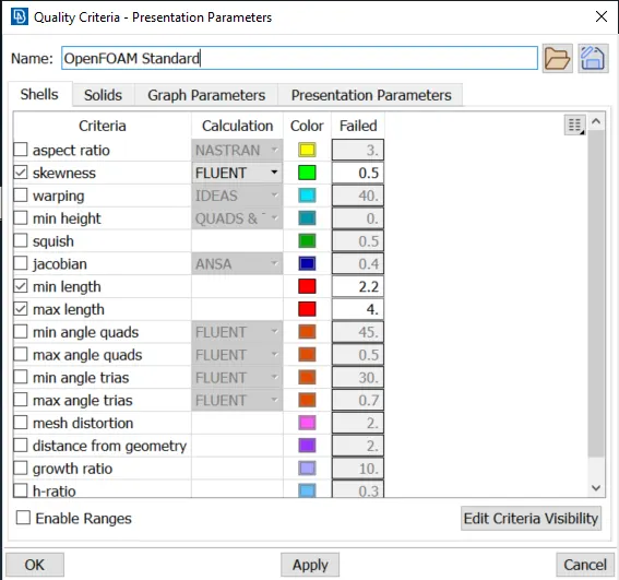
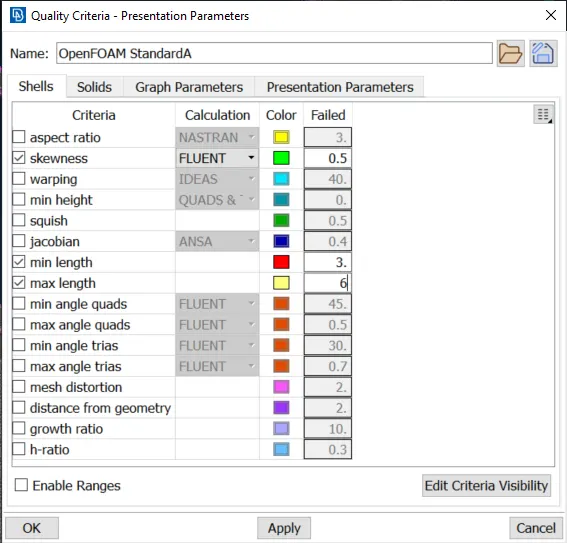
Assuming different quality criteria (min length and max lenth ) for different PID's:
| S.No | PID's | Target length(mm) |
|---|---|---|
| 1 | Body | 5 |
| 2 | Roof | 4 |
| 3 | Lights | 2 |
| 4 | Wheels | 3 |
| 5 | Windows | 4 |
LIGHTS:
Quality criteria and mesh parameters:
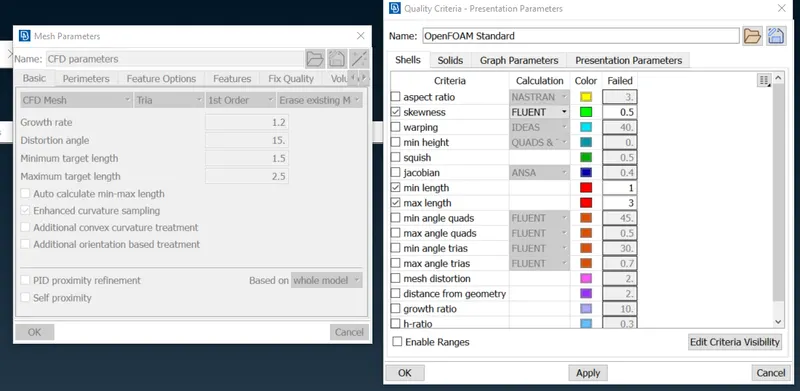
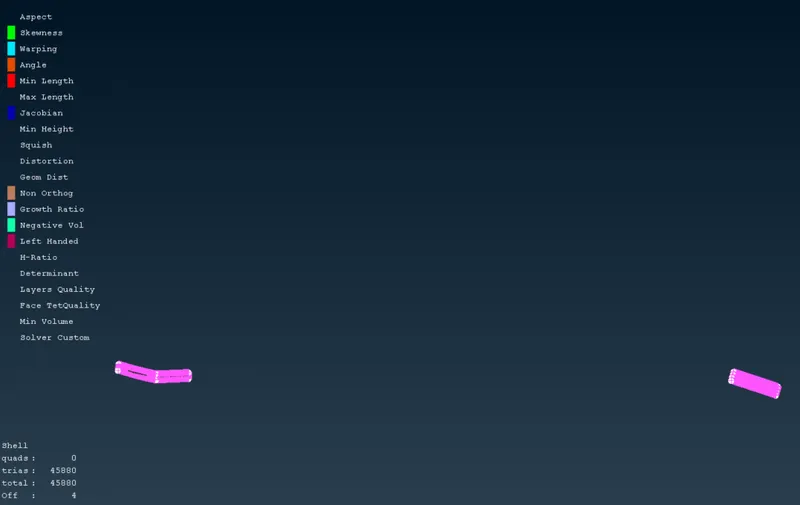
After meshing we can see there are a lot of off elements, we can rectify them by doing some geometry clean up and reconstructing the mesh.
from the above image we can see the off elements are rectified and a fine mesh is obtained by recontructing the mesh.We should follow the same procedure for rest of the PID's
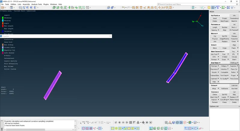
we can see there are no off elements after recontruction of the mesh.
Wheels:
Quality criteria and mesh parameters:
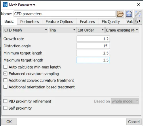
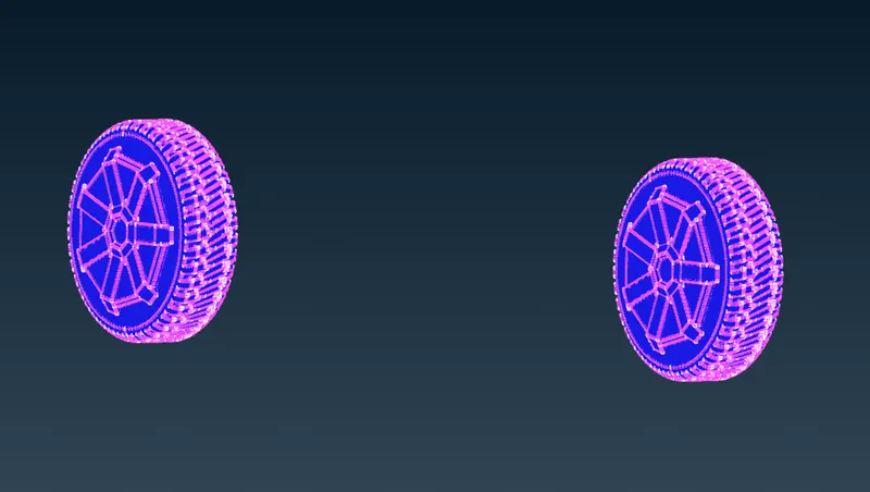
The tires are fully meshed without any errors.
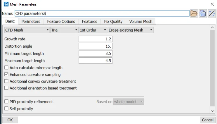
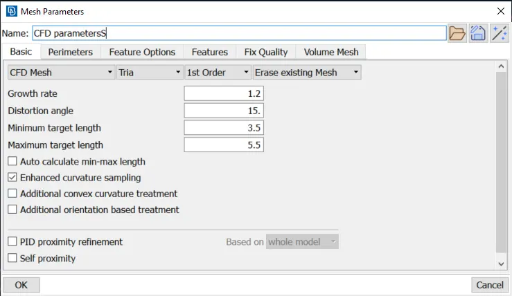
Quality criteria and mesh parameters(4mm):
Roof:
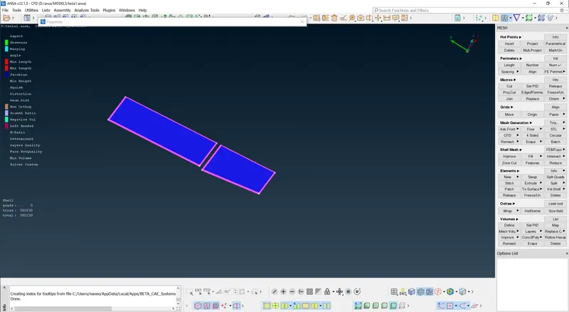
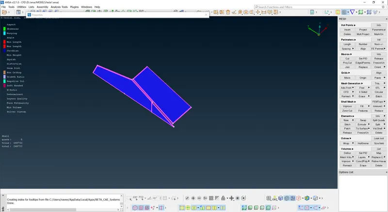
Windows:
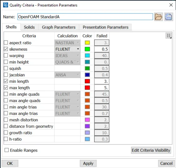
Quality criteria and Mesh Parameters(5mm):
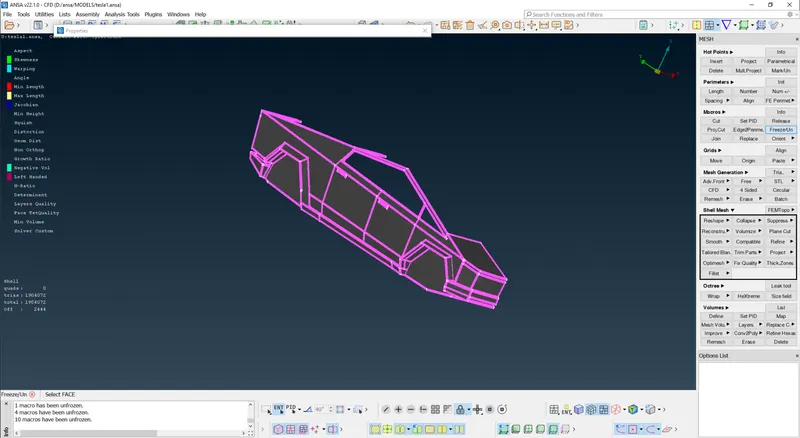
There will some off elements at the point of interaction, the off elements on the surface of the body are rectified, the off elements at the point of interaction are ignored.
Since the whole half of the car is meshed, we can just simply transform the model to create a whole car model.
To get the whole car model we are doing transform and then symmetry with respect to three point plane. And then doing a final geometry check.
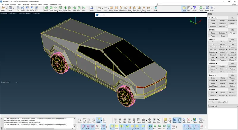
Fully assembeled car model:
Final geometry check:
WIND Tunnel:
Data for wind tunnel are as follow:
The wind tunnel dimensions are, if x is the lengths of car then
Front of wind tunnel is 4X from the car.
Rear of wind tunnel is 6X from the car.
Top of wind tunnel is 3X from the car.
Side walls of wind tunnel are at X from the side portion of the car
Bottom of wind tunnel is in close proximity of wheels
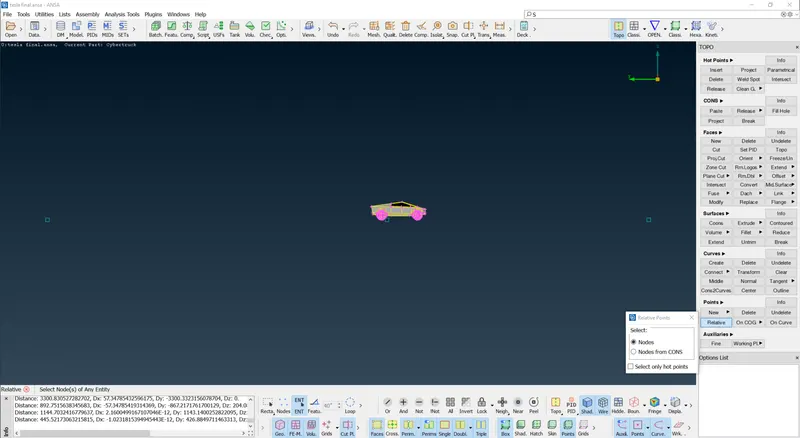
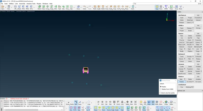
Points are created by using 'Reative option' in points of Topo Deck.
- Total length of the car 5906mm.
- Inorder to create a Wind tunnel, first create a point at a distance of 400 mm at the bottom .
- By taking that point as reference, we create anotheer point to front of car at a distance of 4914+4* 5906 = 28538 mm(4194 mm is distance from the created relative point to the front point of the car).
- Then we create another point at the back at a distance of 1590+6* 5906 = 37026 mm (1590 mm is distance from the created relative point to the rear most point of the car).
- Then we create top face by using offset at a distance of 3* 5906 = 17718 mm.
- Then the side wallls can be created at a distance of 5906 from the reference point.
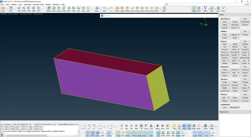
- Now using these two surfaces we create new surfaces on all sides and close the volume , such that it forms a wind tunnel .
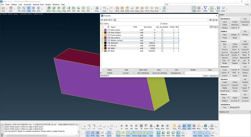
- Now we create and assign PID's for the wind tunnel walls.In the below image we can see that PID's are created and assigned .
Creating a reference point at the bottom:
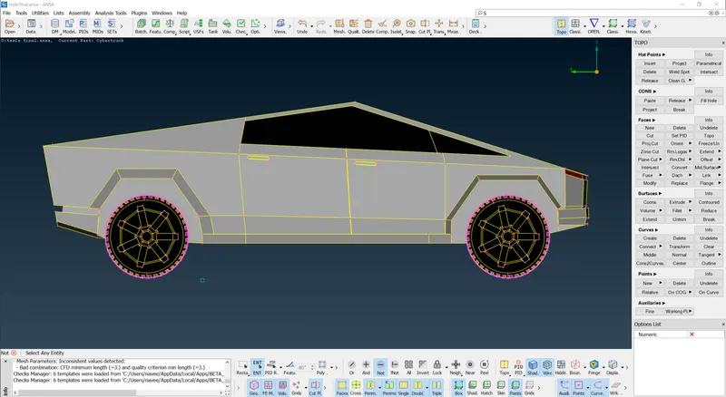
With the help of the reference point creatimg a point at front and rear:
Then similarly creating points at top and then sides:
Then we have to connect the points using curve option to create the walls.
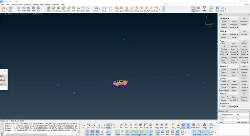
We can offset the bottom surface at the top to create the top suface and we can delete the unnessary points and deleting the created curves. Then with the top and bottom surface as reference we can create the side walls.
Defining the PID's for the wind tunnel:
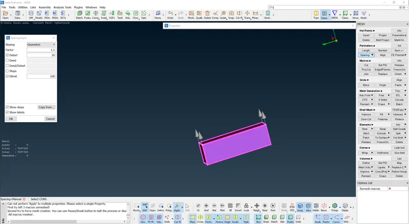
As the analysis of what happens over the surfaces of car is of importance so the bottom of wind tunnel should have good resolution as compare to the top portion as it relatively at larger distance than botttom. So mesh length of 20 is taken at bottom and 100 for top portion.
As the front and rear of car are connected with the top and bottom surfaces then the mesh length for this surfaces should vary from 20 to 100 from bottom to top portion. This gradual variation can be achieved using Spacing option from the perimeters section of Mesh deck.
Perimeters- Spacing -Geometric -factor of 1.1 and d-min of 20 successful application of this will be indicated by upward pointing arrows.
Meshing of the walls:
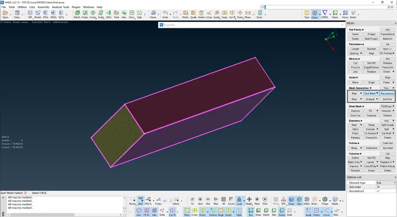
Fully meshed tunnel:
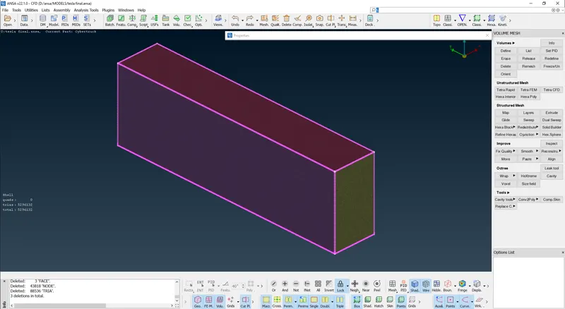
The final mesh:
Since performing volumetric mesh required 2-3 days so we are not performing it.
Learning Outcomes:
- Got familiar with more complicated and advance ANSA tools
- Learnt about volumetric meshing along with 2D meshing.
- Selection of volumes for volumetric meshing
- Different mesh length sizes tend to give errors at the contact regions of 2 different mesh length regions, therefore mesh ranges can be given to avoid erasing of mesh.
- Learnt how to create a wind tunnel and Using spacing option in surface meshing helps in having varying mesh lengths along the surfaces.
- Learnt how to clear any off elements created while meshing using reconstruct option.
- Got familiar which types of off elements are justifieble.
- Using the mesh modifying tools like move, split and smooth options.
Results:
Complete car model with wind tunnel ANSA file:https://drive.google.com/file/d/1mTu6AZ9oPu8igbV_TzWxf0MG4inZ5URa/view?usp=sharing
Learning outcome:
In this process of working on this project we have learned how to,
- Identifying & cleanup of the topological / geometry errors .
- Geometry check-up and setting-up of relevant PID's and defining the element size or length .
- Setting the mesh parameters and quality criteria, selection of meshing type and generating surface mesh of the CAD model .
- Use Quality criteria tool & also learnt various options under the shell parameters such as Skewness, min length, max length , max angle &min angle, etc.
- Resolving the errors such as skewness, min & max lengths using various tools.
- Set-up Wind Tunnel as per given dimensions for external flow CFD analysis and surface mesh of wind tunnel .
Conclusion :
- The imported CAD model of Tesla cyber truck is Topologically Cleaned & Corrected all the feasible surface errors to perform external aerodynamic analysis.
- Surface mesh is generated with the required element size.
- Reconstructed the mesh as per the mesh quality required at Corners & at Intersection of edges.
- Worked with the errors occured in the Mesh.
- Created a wind tunnel For external aerodynamic analysis.