Project 1 : CFD Meshing for Tesla Cyber Truck
Tesla cybertruck
Objective :
- To Identifying & cleanup all the topological errors in the given Tesla Cyber Truck Car model.
- To create a surface mesh.
- To Create a wind tunnel around Tesla Cyber Truck Car .
- To create a volumetric mesh to perform an external flow CFD analysis simulation.
Introduction :
ANSA :
- ANSA is a Computer-aided engineering tool for Finite Element Analysis and CFD Analysis widely used in the automotive industry. It is developed by BETA CAE Systems. The software is distributed world wide by a number of BETA CAE Systems subsidiaries and business agents.
- ANSA maintains the association between CAD geometry and the FE mesh. This means that the FE meshes are better representations of their geometric parents. Also it is easy to maintain and update any changes in the geometry by simply reworking the updated area instead of recreating the FE from scratch.
- It carries several proprietary algorithms for meshing suitable for both CFD and structural models. ANSA was initially standing for 'Automatic net generation for structural analysis' , but the software has gone beyond that very quickly. ANSA has broadly six menus which are used to do various activities those are: TOPO MESH, VMESH ,DECK-SOLVER, MORPH ,HBLOCK.
Different type of modules in ANSA :
- TOPO - Set of tools for Geometry clean-up and for setting up of PIDs.
- MESH - Tools to generate Surface Mesh or 2D Mesh.
- VOLUME MESH - To generate solid or 3D Mesh.
- SOLVER DECKS - Tools based on different solvers such as ABAQUS, RADIOSS ,ANSYS etc.
- MORPH - Advanced tool to capture geometry more accurately while meshing.
Solution procedure :
- For solving we follow the below procedure ,
- Import the CAD model.
- Identifying & cleanup of the topological / geometry errors .
- Geometry check-up.
- Setting-up of relevant PIDs.
- Defining the element size or length.
- Setting the mesh parameters , selection of meshing type and generating surface mesh of the CAD model .
- Resolving the errors in the surface mesh.
- Creating the wind tunnel for external flow CFD analysis and surface mesh of wind tunnel.
- Generating volumetric mesh.
- Let us start solving one by one by following above steps :
1) Importing CAD the model :
- To import the CAD model we follow below steps,
Go to file -> open -> browse the location of the CAD model -> select it click on open.
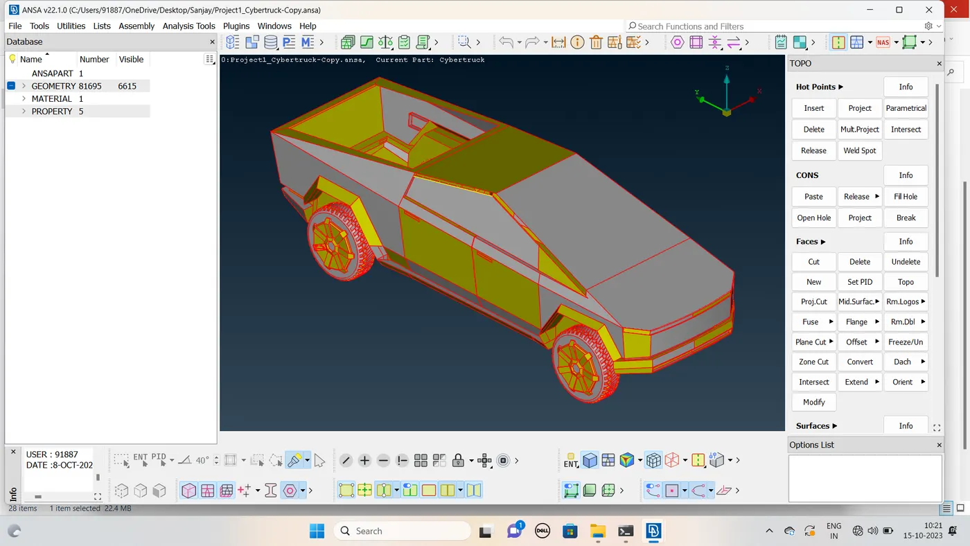
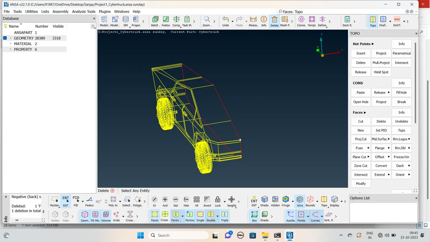
- Here in the above image we can seeonly single cons , let us do topo for whole model , then we can get clear idea of model and actual single cons .In the below image you can see the model after performing topo .
- The model which we have imported opened in ENT mode , we can see the PID mode by selecting PID mode in the bottom layout.The below image is the PID mode of our Tesla cybertruck Car model .
- In the wireframe mode of our model model we can see the errors like single cons . Let us clear the topo errors one by one.
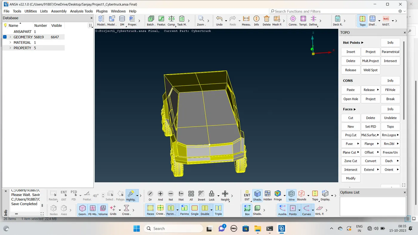
Symmetry:
- Cut the half of the model
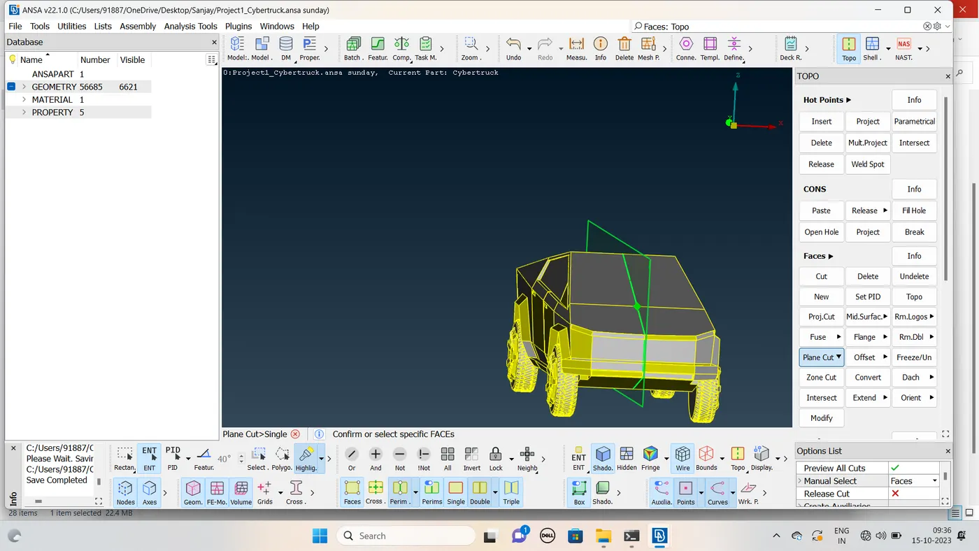
- Start the topo cleanup
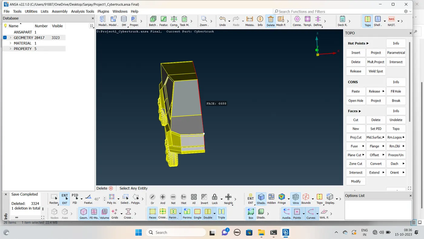
Check the Geometry all cons present in double.
Final Geometry
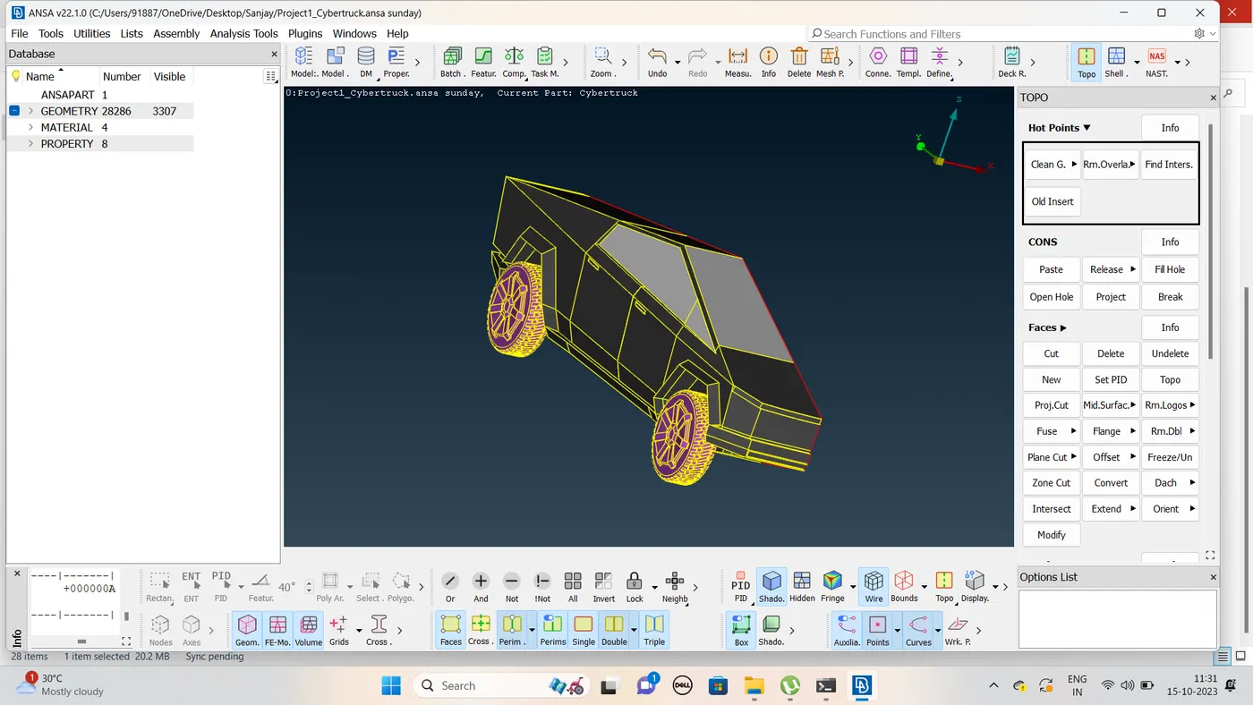
-
2) Identifying & cleanup of the topological / geometry errors :
- Before performing any topo clean up , you can observe that the resoution of compenents are not very much good . So to have a better resolution let us first go to mesh deck and decrease the mesh length by selecting the whole model and giving 1mm mesh length .Now you can observe that in the below image the resolution of car is pretty much good .
- As we seen that the given geometry has several topological errors, missing faces which are indicated by single cons & triple cons, but for the CFD analysis only the double cons are preferred not even the triple cons are acceptable because it may lead to forming a local volume over there.
- Here , the main aim is to create whole car inside part as one as one volume,here tyres are inserted into the body but not attached .Here we can go with two approches either we can delete the common extra part and perform topo and make the whole cars and tyres as one volume or we can delete the common part and close the the holes such that only car forms one volume and as tyres are not attached , then each of them forms one volume means 4 tyres 4 volumes . Here we follow the second approach it will be much better . And with these 5 volumes another volume forms between car and wind tunnel ,which is the volume we needed .So we delete all other volumes and keep the final volume as we ae doing external flow analysis .
- Initially, there were many errors , each of them should be rectified systematically by one after other. The errors are being corrected by selecting the individual features of the car like lights, wheels, windshield , body etc., seperately.
- Here, also we are much concerned about outside features of the car and not about inside features .We have to modify all the features such that we get whole car inside part as one volume .
- So to have the whole model as single volume we should have only double cons and even with double cons we should not have a feature closed on all sides ,it may lead to form a seperate local volume over there .
- Also when you find any small surface delete it and its neighbour surface and create a large surface such that we dont have any quality criteria error while meshing .
- So we will delete the surfaces which are not necessary and causing an error or leading to cause a local volume .
- If you are not clear about the selection always zoom in and select the right surface . Also use wireframe mode for proper selection (Cntrl + shift or directly turn off shadow mode ) .
- Here we always shift between PID and entity mode depending upon the suitability to solve particular problem .
- Here in all the cases , depending on the situation we use any one of the tools like project , extend ,cut , topo ,new coons etc. to clear topo errors .
- So by following above points , let us select one by one and clear topo errors .
- Let us first start cleaning topo errors for body part and then let us go with wheels .
-
Setting-up of relevant PIDs :
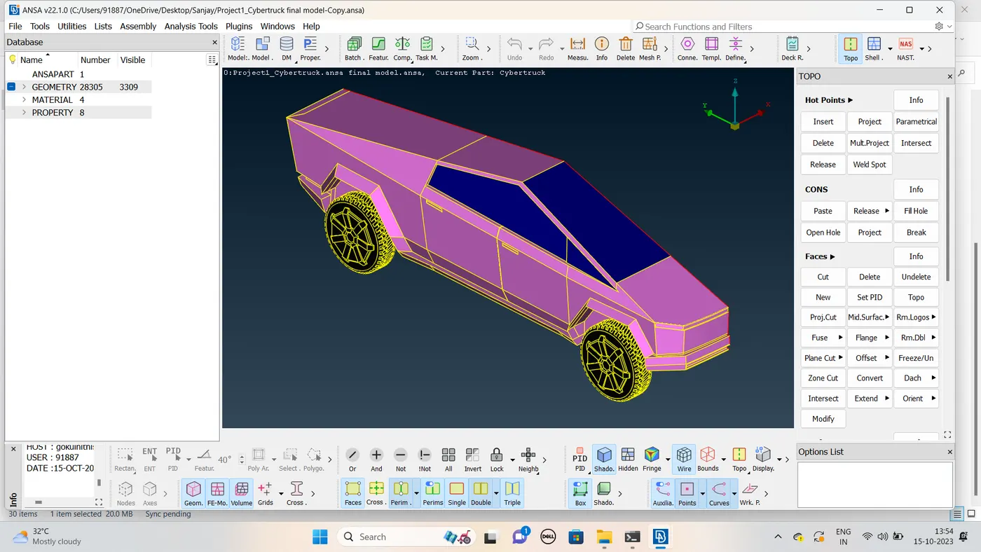
- Transform the model other end
- Again the topological cleanup
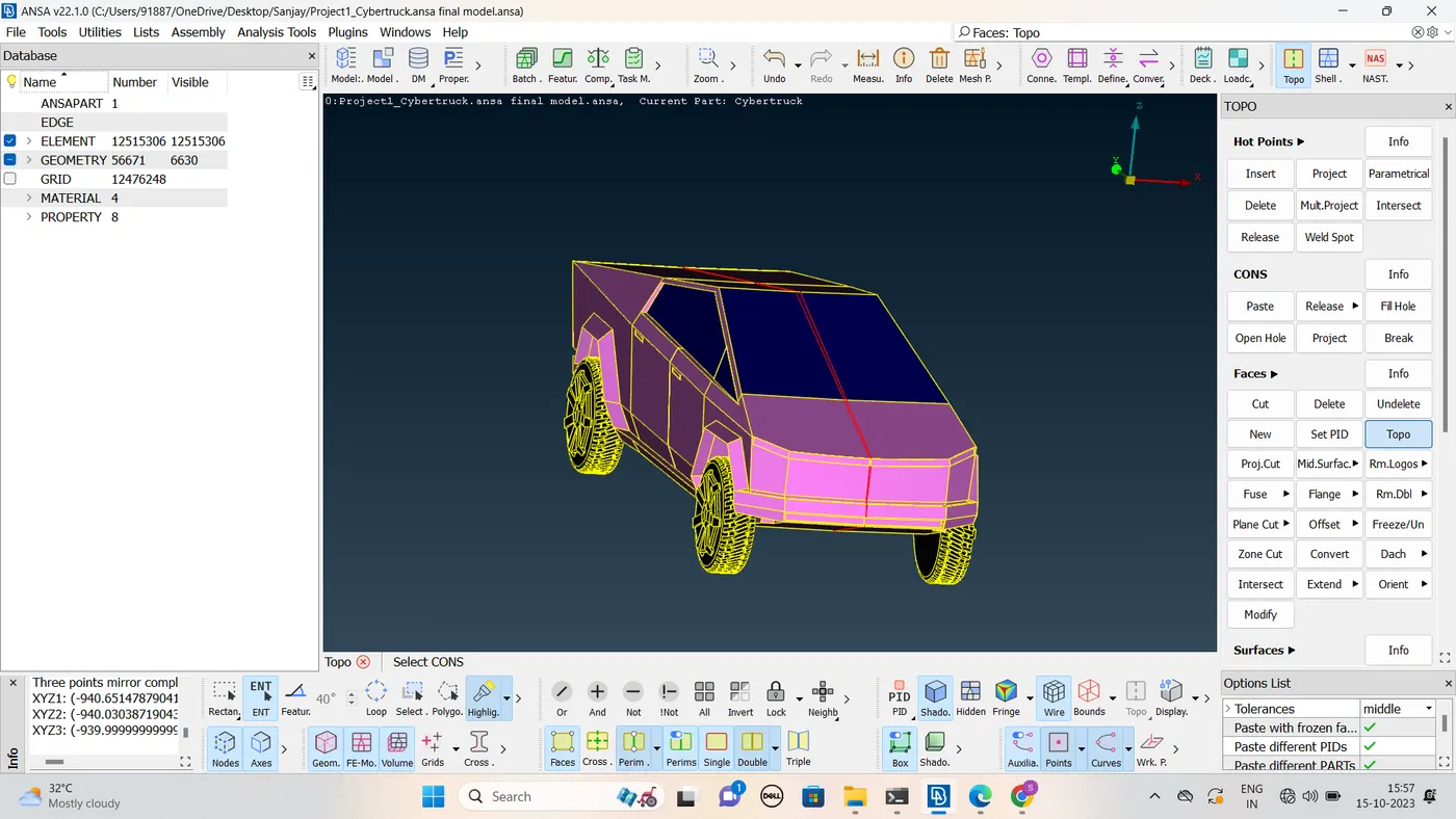
Final transform geometry
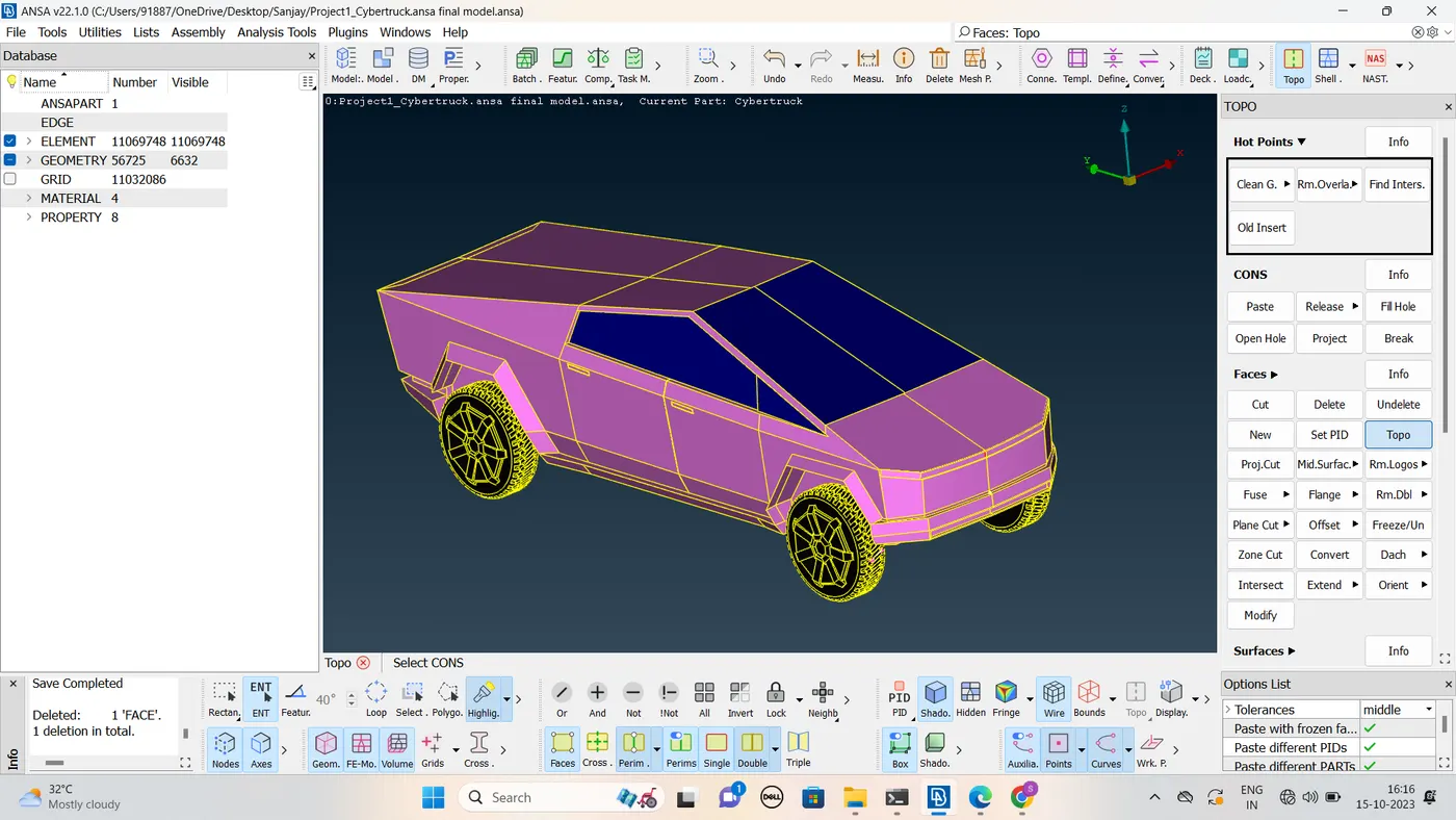
- Topological cleanup done
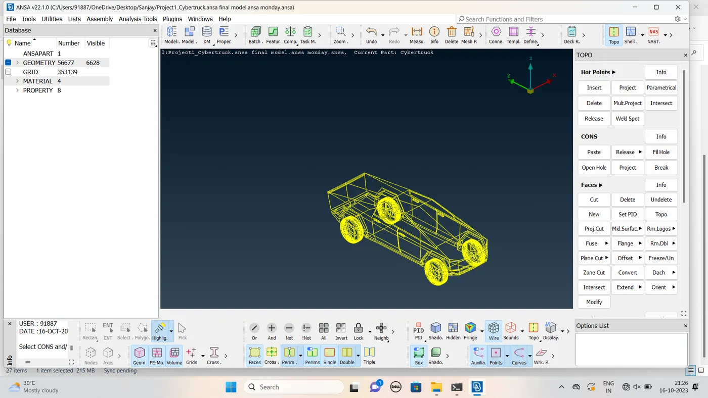
-
- In this step we assign the PID for different parts and give a name and colour to differentiate between the components and ease up the working on the components individually.This is also done to specify names to different boundary conditions for various parts.We need to activate cross hatches before setting-up PIDs.
- If you open properties manager at the top , you will have some default PID's which are assigned. We have to create new PID's to assign for our components. Inorder to create new PID , right click on properties manager -> click new -> then select pshell -> then again select pshell -> then give name in the popup box -> then ok .You can change the colour by double clicking on the colour box -> then ok .
- In the similar way create PID for all the components.
- Let us also add transperancy for windows to be more realistic in the colour box .
- Then next thing is assign these PID's to the components of the geometry .
- To apply , we select /click on the PID to apply in the PID manager -> then right click on it -> then click on apply -> then in the geometry select the cross hatch of the surface you want to assign -> then middle click . In the similar way we have to apply PID's we have created . To give the PID we select with the different type of selection available to select the exact surface needed.
- Then after assigning the PID , delete the empty orginal PID's which has no components assigned by using compress .
- In the below image you can see that list of PID's that we have assigned.
- Meshing
- We start meshing from smallest component to larger component one by one .
- We mesh the body PID last because as it is attached to lot of other PID's if you mesh it first and mesh other PID attached to it later it may lead to erase of mesh of body at that location .For this reason we mesh the body PID last .
- We isolate each component/PID and give above quality criteria(target, min and max length ,skewess etc. ) in quaity criteria and then in mesh parameters .We also select skewness and give value as 0.5 for all the PID's and also min angle trias as 0.7 .You can see the quality criteria given in the below image , we change only min length and max length based on the PID.We give the values for quality criteria as in the above table .
- Here then we will select the Meshing algorithm and then finally we perform meshing.We follow below steps for that ,
-
Go to Mesh Generation -> spot Mesh -> tria -> drag and select the required model -> click on the scroll button/ middle mouse button on mouse to mesh (or) we can directly select visible under drop down menu of spot mesh instead of drag and select the entire model after seperating them by using NOT .
- After meshing we remove the off elements of that particular PID byselecting the hidden mode .
- In the hidden mode you can see the off elements with the colour you have selected for that quality criteria in the quality criteria menu .
- After meshing we will see some off elements , we can remove most of them by using reconstruct under shell mesh ,and further if you have any off elements we have to go the location individually and clear that off element .
- When you have off elements , you can go to topo mode to see clearly. If possible to do it in mesh mode do it ,so that you will not loose mesh .
- If you want to remove any con it's better to remove it in the mesh mode ,so that mesh will not erase .If you go to topo mode and remove any con or surface or create a new surface the mesh will be erased .So if possible it's better to remove it in the mesh mode .
- We can remove the remaining off elements by removing mesh improvement tools . we can use split , smooth ,paste etc.We have to use mesh improvement tools depending on the situation .You can view better by using neighbour 1st level .
- We have to use move grid only if necessary , by using it may lead to change in shape of geometry as we move boundary grids.
- By following above steps start we start meshing with rearlights and then clear off elements ,such that the off element count goes to zero (0).
- In the below image we can see the lights PID with no off elements .So let us mesh another PID .
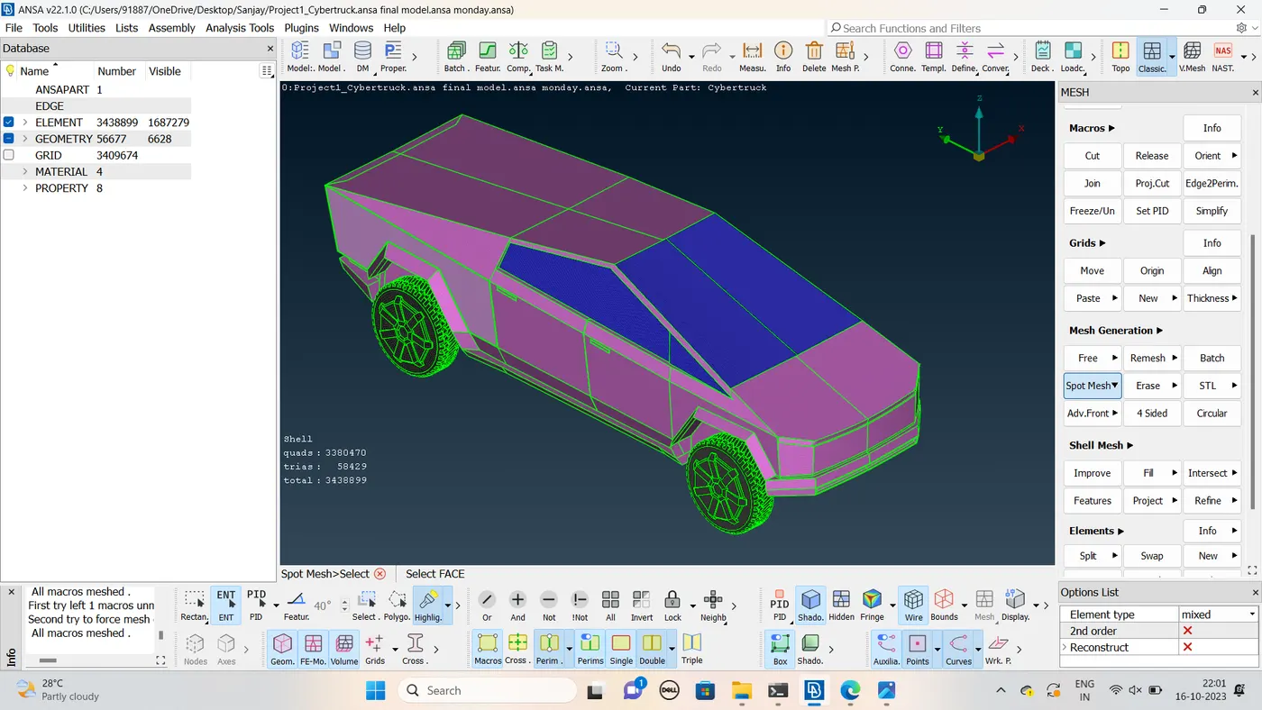
Mesh the Cybertruck
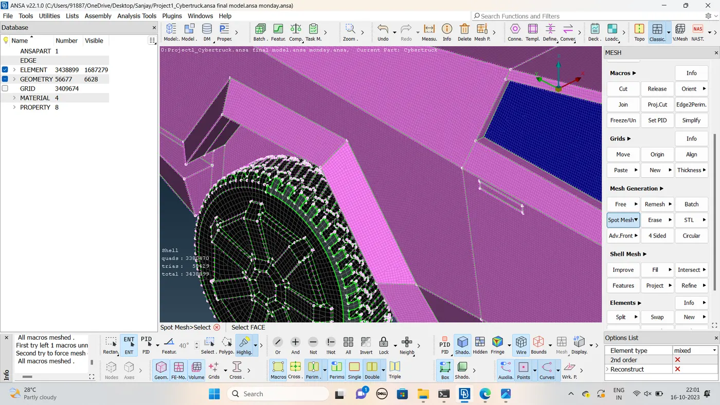
Elemnets count -3438199
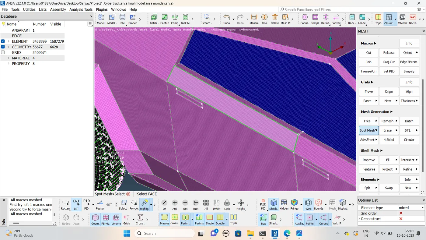
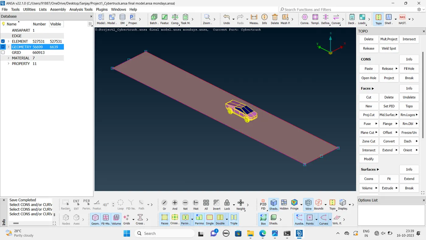
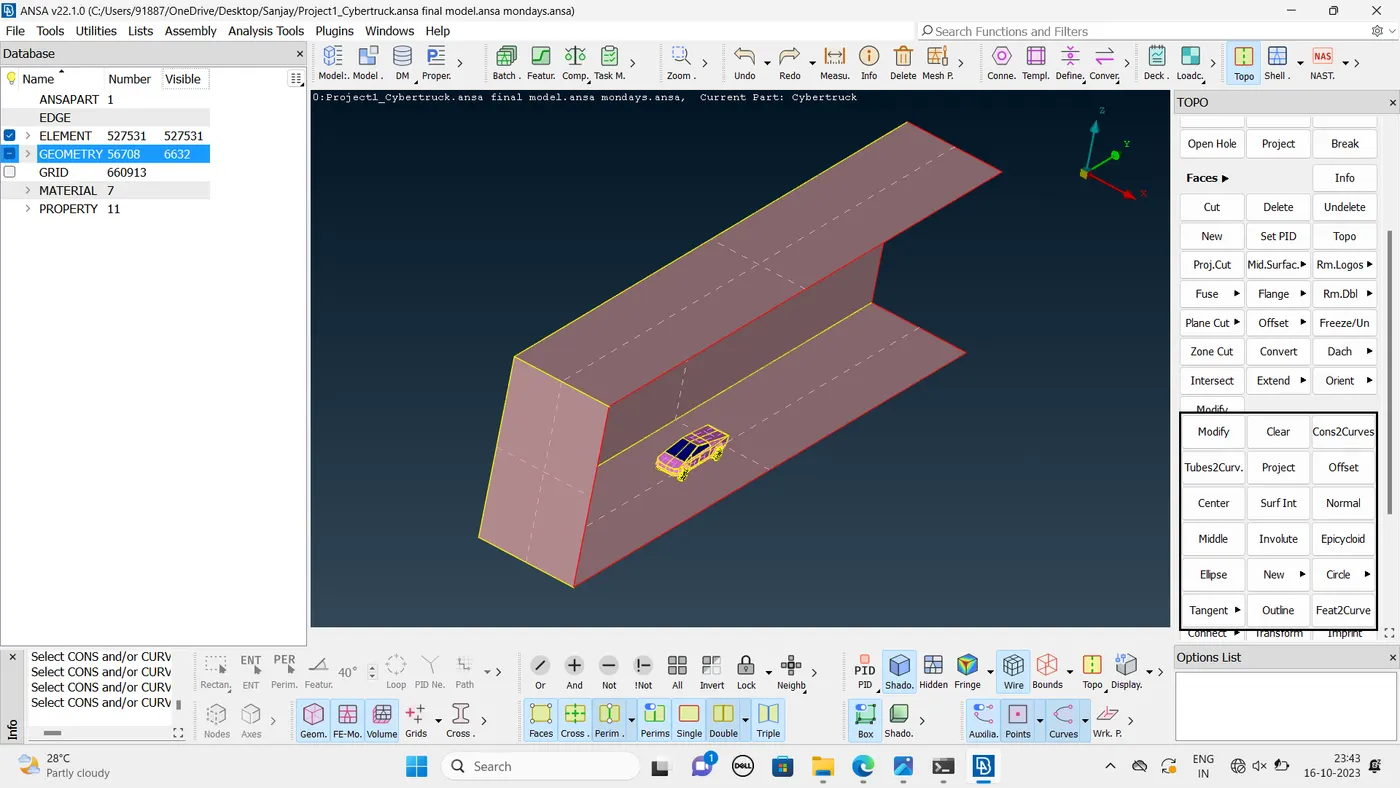
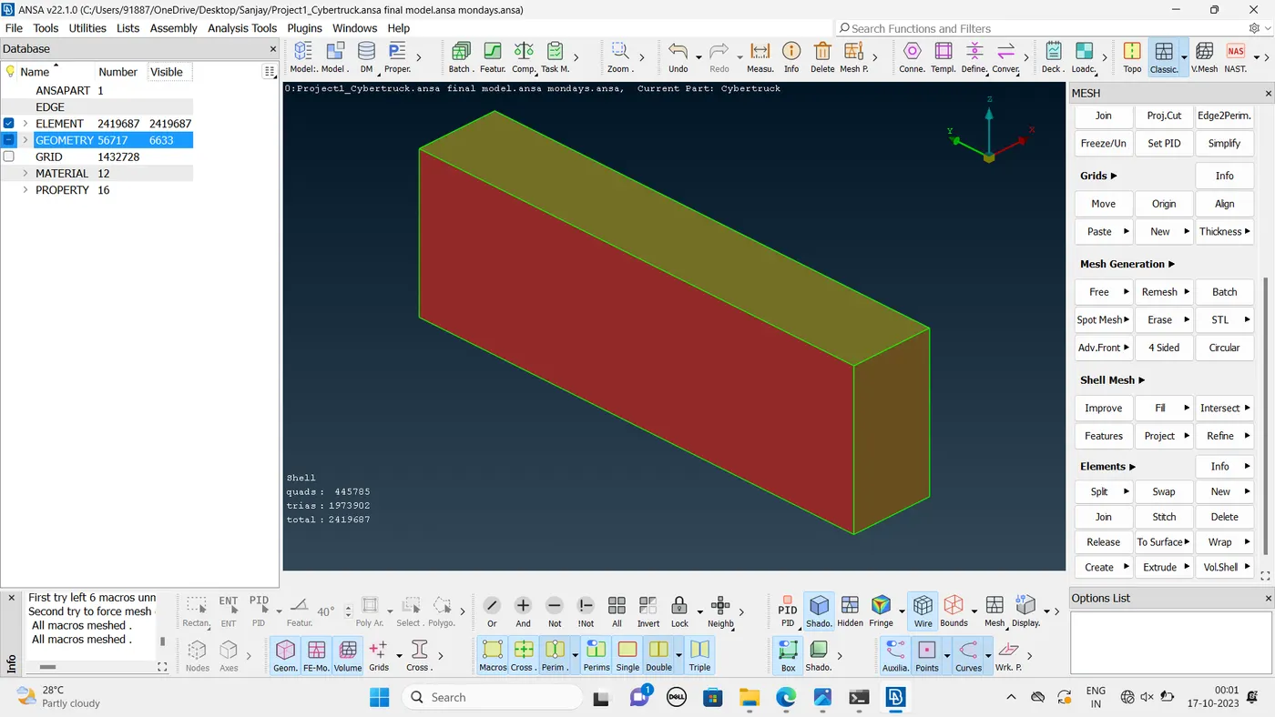
Wind tunnel
- Create the wind tunnel Depend upon of the model
- Front portion 4*car length
- back portion 6*car length
- Finally create the wind tunnel
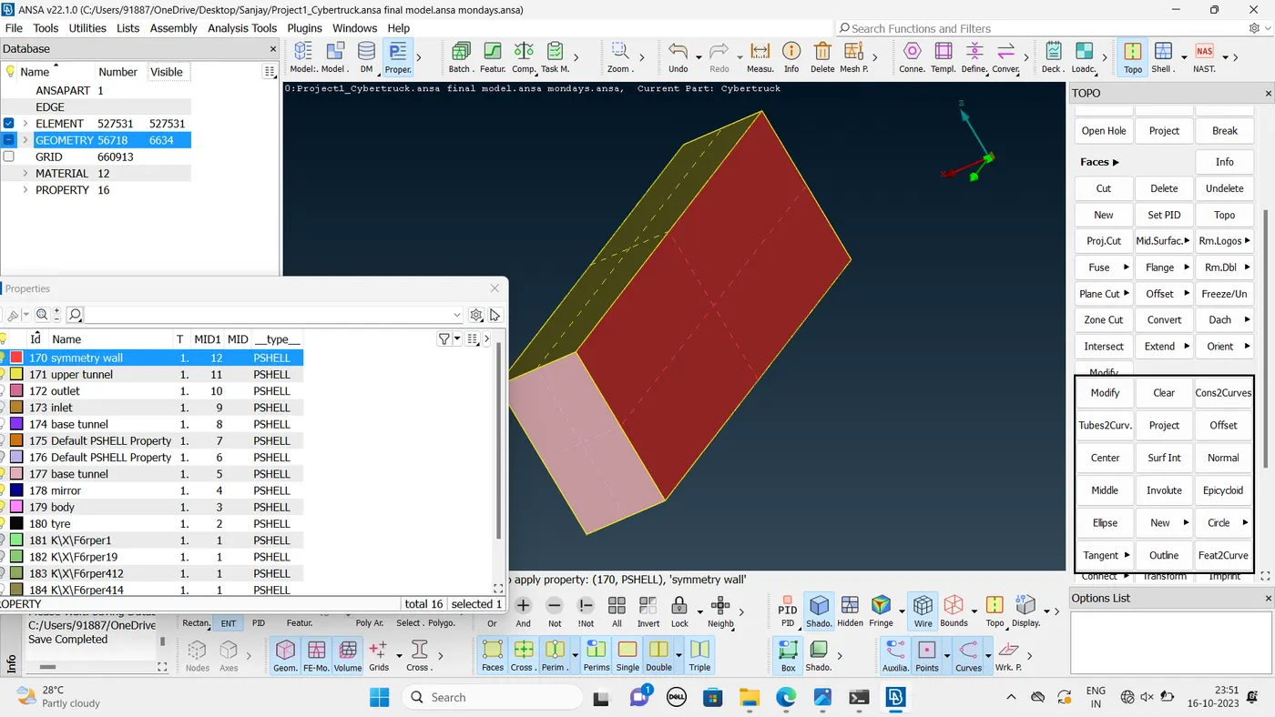
Create the PID mode to the wind tunnel
like Inlet ,Outlet,Symmetry wall,Upper wind tunnel ,Base wind tunnel.

Start the meshing of the model wind tunnel.
Learning outcome:
In this process of working on this project we have learned how to,
- Identifying & cleanup of the topological / geometry errors .
- Geometry check-up and setting-up of relevant PID's and defining the element size or length .
- Setting the mesh parameters and quality criteria, selection of meshing type and generating surface mesh of the CAD model .
- Use Quality criteria tool & also learnt various options under the shell parameters such as Skewness, min length, max length , max angle &min angle, etc.
- Resolving the errors such as skewness, min & max lengths using various tools.
- Set-up Wind Tunnel as per given dimensions for external flow CFD analysis and surface mesh of wind tunnel .
Conclusion :
- The imported CAD model of Tesla cyber truck is Topologically Cleaned & Corrected all the feasible surface errors to perform external aerodynamic analysis.
- Surface mesh is generated with the required element size.
- Reconstructed the mesh as per the mesh quality required at Corners & at Intersection of edges.
- Worked with the errors occured in the Mesh.
- Created a wind tunnel For external aerodynamic analysis.