Project 1 : CFD Meshing for Tesla Cyber Truck
About ANSA :
- ANSA is a CAE tool for Finite Element Analysis and CFD Analysis used in the automotive industry.
- ANSA maintains the association between CAD geometry and the FE mesh.
- It use has different tools that are present in different modules.Some are listed below.
1. TOPO module: Helps in fixing the topology of the model.
- Insert:It creates hot points on cons or 3d curves.
- Topo: This function automatically creates topological conditions between selected adjacent CONS.
- Project: It defines a new hot points or new cons as the projection of existing hotpoints or cons.
- Parametric:Defines new hot point on a existing curve or con parametrically.
- Multi-Project: It defines a multiple new hot points as the projection of existing hotpoints at a time.
- Cut: splits or joins existing faces.
- Intersect: Used to define the intersection between two surfaces penetrating each other.
- Create new surface
- Coons: This is an easy way to define a new surface by its boundary curves.
- Fitted: The FITTED option is used for the definition of a non-planar Face. The created Face fits to the selected boundaries.
- Conc2Curve: This function defines 3D-curves from existing CONS, shell/solid edges, Line Elements end Cross-sections.
- Relative: This function creates new 3D-points that lie on a given relative position from a number of selected points.
- Orient: It sets a uniform orientation direction to all visible Faces according to the orientation of the majority of the Faces.
2. Mesh module : Helps in meshing using different mesh algorithm and mesh tools.
- Length: Helps in setting the element length on selected perimeters or macros.
- Spot mesh: It creates automatic mesh for macro and finite element shell mesh areas by using special meshing method for macro areas and gives better result than free mesh in case of weld joints.
- Reconstruct: Performs re-meshing after examining existing mesh to correct problematic areas and optimize the overall quality of the mesh according to the mesh parameters.
- Spacing: Manual control of nodal spacing and distribution on perimeter segment. It can be used when there are varying mesh lengths.
- Split: It helps in spliting quadrilateral and triangular shell elements into smaller ones.
- Move:Help to mode nodes.
- Orgin: This function moves the selected grid points to their original position
3.V. Mesh module: Has tools for volumetric mesh.
- Volume>Define: It automatically defines multiple volumes using already meshed macros or FE-model mesh.
- List: Activates list function.
4. Set PID: This function assigns selected Faces, Shells or Groups of entities to an existing or new PID.
5.Universal Delete: The delete option is used to delete all the entities which are selected.
6. Loop: Helps to select multiple cons connected to each other at a time.
7. Fill Holes: Fills the holes and holes present in the model.
8. Compress: Compress files size by removing unwanted and unused entities.
9.Wire: To see model in wire frame mode.
10. These tools are used to see entities or hide entities and are very useful while inspecting then model for errors.
Not tool: Use to hide a surfaces or PID.
And tool: Helps to find the neihbouring surface belonging to selected con or PID.
!Not tool: Help in isolating multiple surfaces and PIDs.
Or tool: Isolating a surface or a PID.
Lock tool: To lock isolated PIDs or surfaces.
Neighbour: To see the neighbouring surfaces or PIDs.
11.Cross-Hatches: Activate and deactivate cross hatches on the model surfaces.
12.PID properties: It is helpful to name the PIDs present in the model and facilitates property management.
13. Compress Tool: To remove alll unnecessary PIDs in PID manager.
14. Measure tool: Helps to measure distances and dimension lengths.
15.Transform Tool: It is used to Translate, Rotate, Transform, Scale, Symmetry or Mirror selected entities (Faces, Points, Elements etc).
16.Cut Plane: It helps to cut the plane as per required orientation.
Meshing quality criteria :
These are used to evaluate the accuracy and reliability of a computational mesh, which is a discretized representation of a domain used in numerical simulations, such as finite element analysis (FEA), computational fluid dynamics (CFD), and other engineering and scientific applications. High-quality meshes are important for obtaining accurate and reliable simulation results.
Element Shape Quality:
Aspect Ratio: The ratio of the longest side of an element to the shortest side. High aspect ratios can lead to poor accuracy.
- Skewness: Measures the deviation from an ideal shape (e.g., equilateral triangle or regular quadrilateral). High skewness can cause numerical instability.
Element Size and Distribution:
- Element Size: The size of individual elements in the mesh. Smaller elements are required in regions with high gradients or complex geometries.
- Mesh Density: The distribution of elements across the domain. Adequate mesh density is essential for capturing variations in the solution.
Element Connectivity:
- Node Connectivity: Proper connection of nodes in elements ensures accurate representation of geometry and physics.
- Element Distortion: The distortion of element shapes due to meshing. Excessive distortion can lead to inaccurate results.
Boundary Conformity: The alignment of mesh edges with geometric boundaries. Proper boundary alignment reduces interpolation errors.
Orthogonal Quality: Measures the angle between adjacent mesh edges. High angles (close to 90 degrees) are desired for accurate simulations.
Jacobian Ratio: The determinant of the Jacobian matrix, which relates the physical space to the parametric space. Low values indicate element degeneracy.
AIM:
- To check and solve all geometrical errors and assign appropriate PIDs.
- To perform surface meshing on the tesla car model.
- To create wind tunnel and mesh the tunnel.
- to do volumetric mesh with tetra elements.
SOLUTION:
Model Given:
Cybertruck
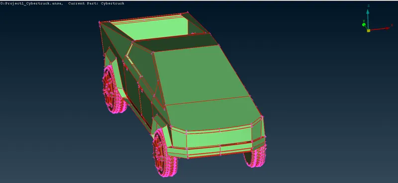
1. TOPOLOGY CLEANUP:
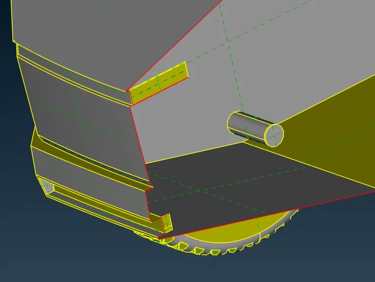
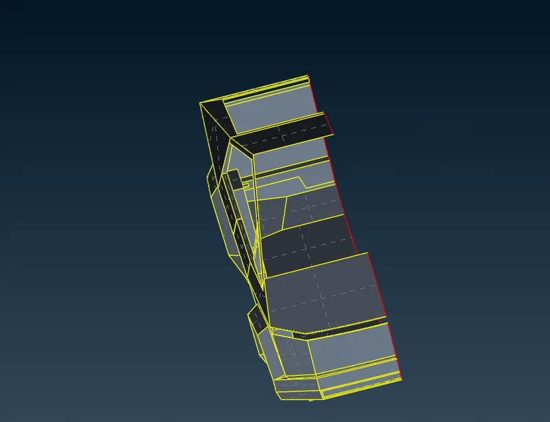
(a) A lot of single cons can be seen in form of red lines evenif there are two surfaces present.
Use topo tool to reduce the single cons and form double cons: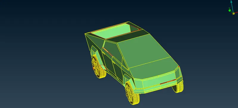
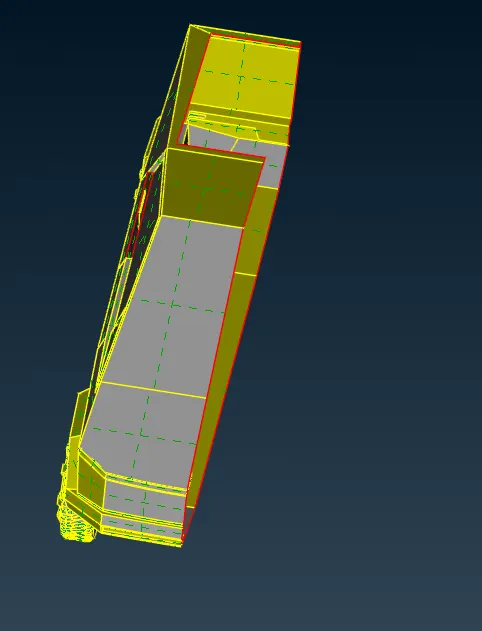
(b) As the model is symmetrical, it is recommmended to remove half of the model having more topological errors using Plane cut tool and delete tool in front view.
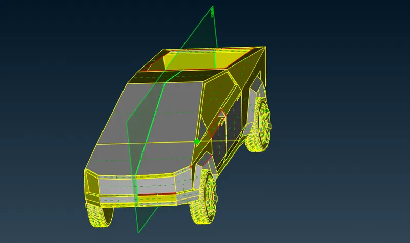
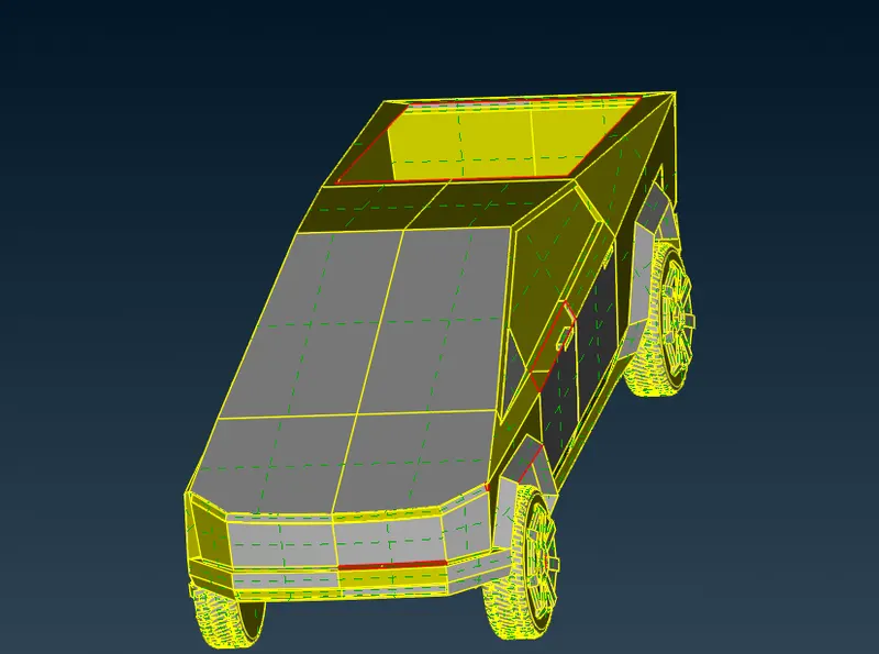
Left half :
(c)Deleting extra surfaces at the plane cut:
After clean up:
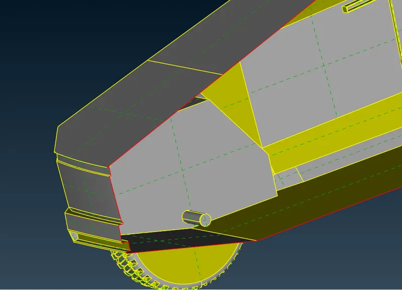
(d) Fixing all the single cons cons present except the the single cons present at the symmetrical cut:
All the single cons are formed due to missing surfaces, thus use fill hole tool to create new faces
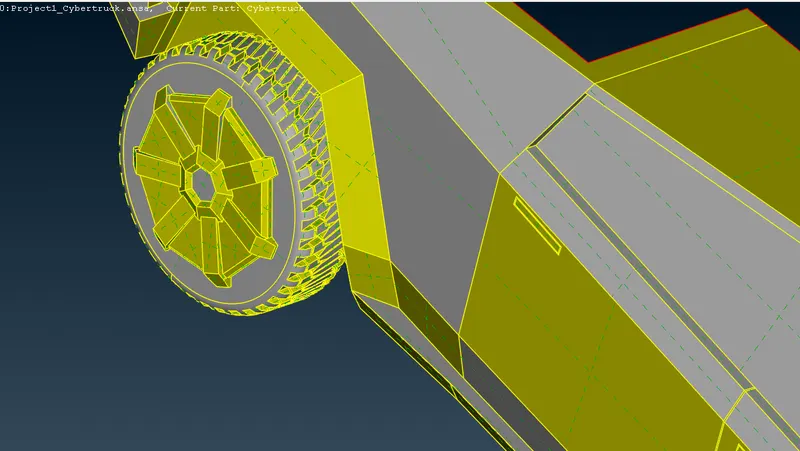
(e) Creating new surface for the rear wind shield:
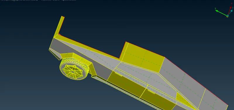
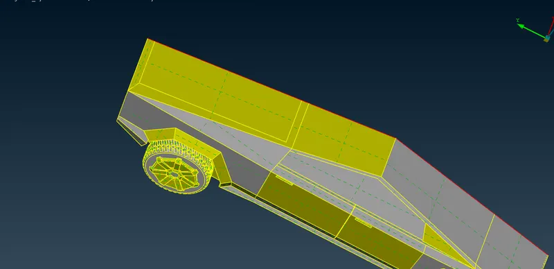
Use Faces>New>Coons tool:
(f) Cleaning the interior of the model to form a single voulume of car body and removing unnecessary voulmes and surfaces:
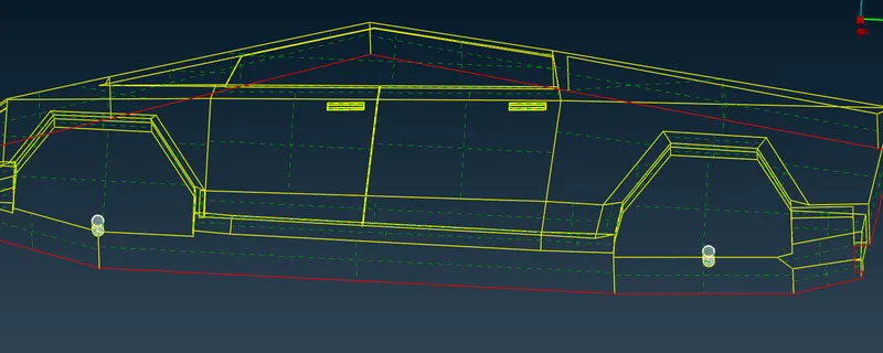 =
= 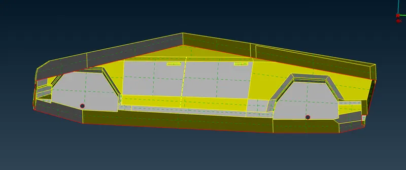
Patching the surface with fill hole.
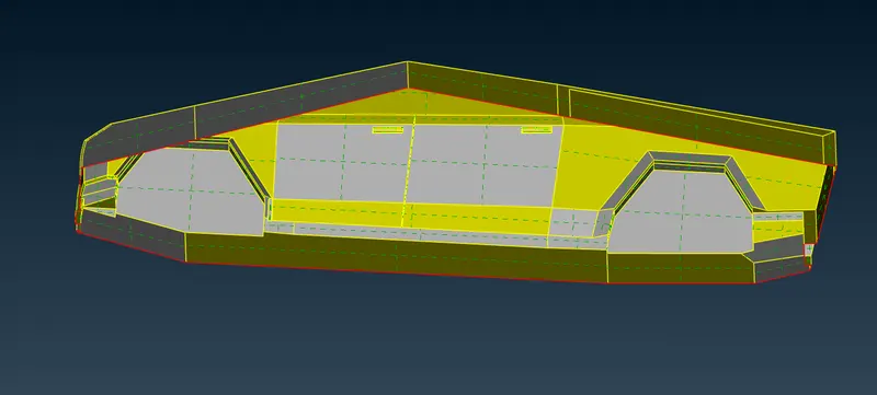
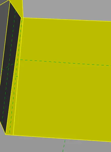
(g) On further checking overlapped surfaces were found.
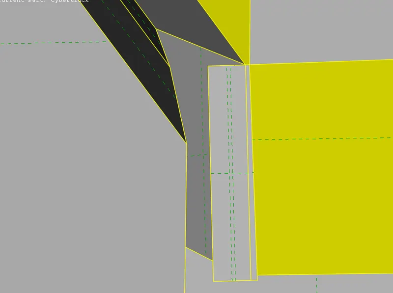
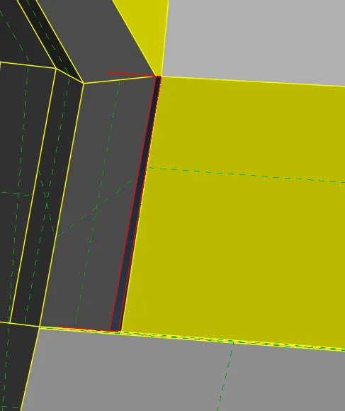
Two cross hatches are found but they are forming double cons, resolved by delete tool, cut and Faces>new>coons tool:
 =
= 
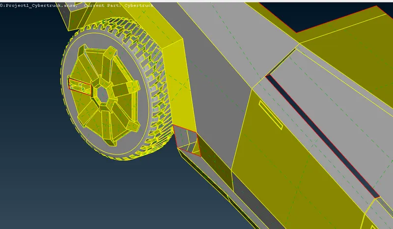
(h) On further inspecting model, a intersecting surface was found near the front wheel area:
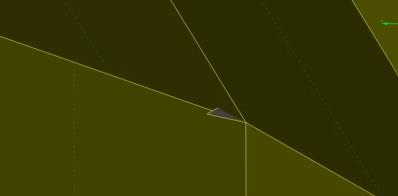
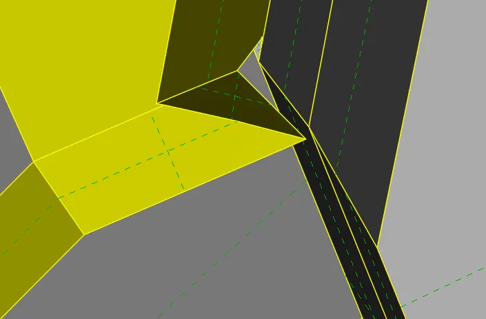
after resolving using Intersect, cut, delete and coons tool:
(i) Checking for more errors using geometry check:
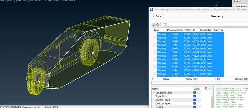
Errors are present as the wheels have holes.
(j) Isolate wheels and resolve errors:
Use !Not tool to isolated wheels and lock them:
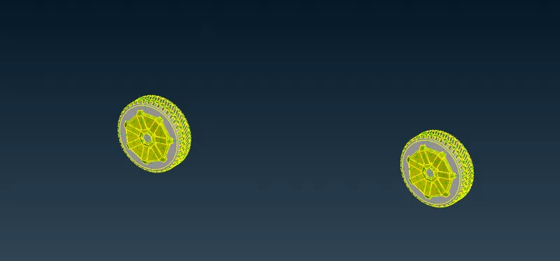
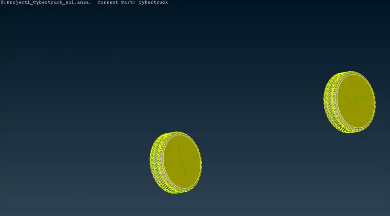
Fill the holes using Fill hole tool:
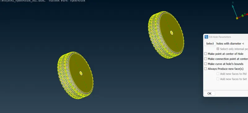 =
= 
(k) Recheck for errors:
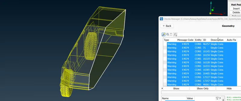
No errors found except the necessary single cons.
2. ASSIGNING PIDs:
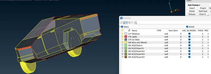
Create New PIDS:
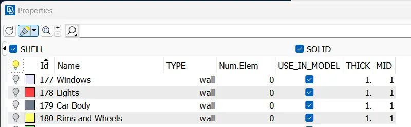
Assign PIDs-
Windows:
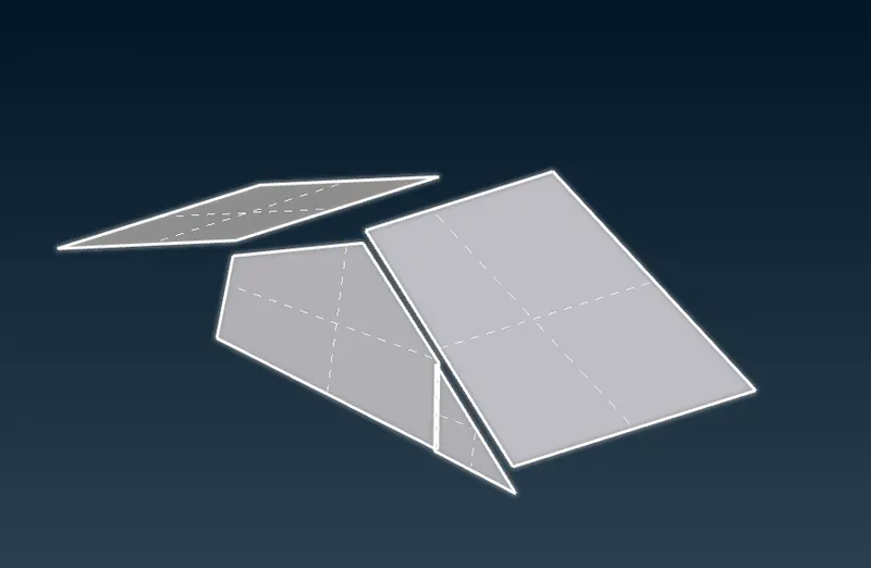
Lights:
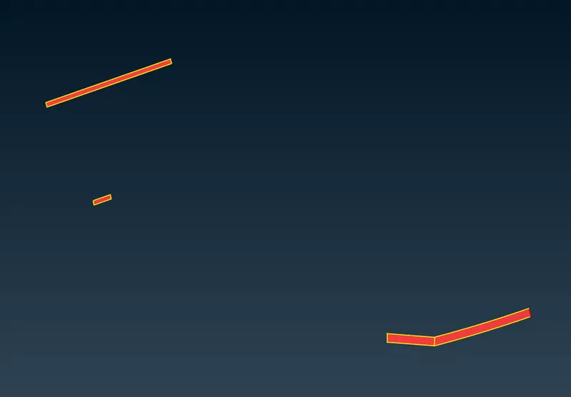
Rims and Wheels:
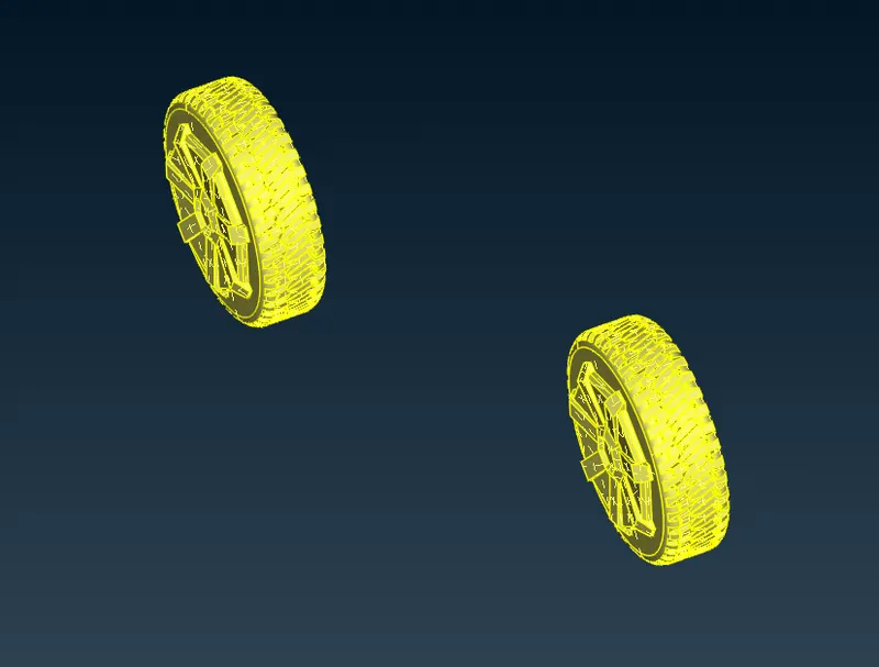
Car Body:
PIDs assigned:
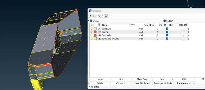
Remove unnecessary PIDs using compress tool:
3. DECIDING MESH LENGTHS OF THE PIDs:
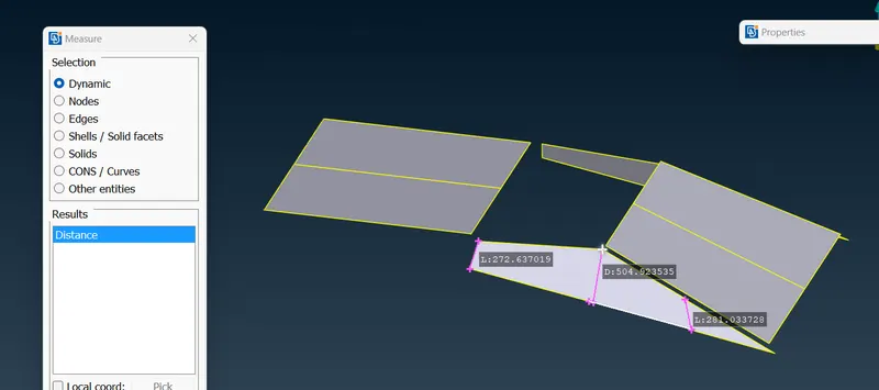
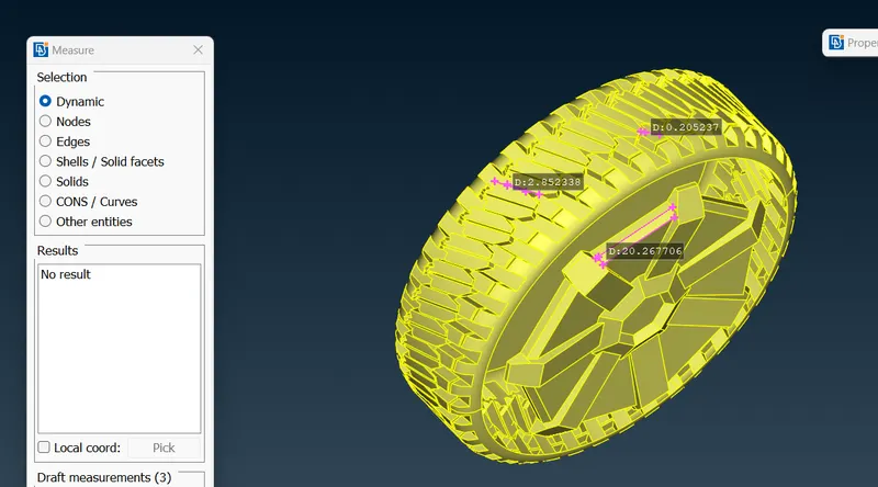
(a) Measure all the parts dimensions one by one and find the miniumum lengths.
(i) Lights
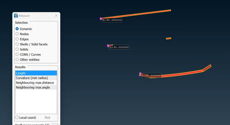
(ii)Windows:
(iii)Rims and tyres:
(iv) car body:
There is no small lengths found.
4. MESHING:
By observing the dimesnions measured earlier, the quality criteria and mesh parameters are taken.
MESH ALGORITHM: SPOT MESH
(a) Rims and Tyres:
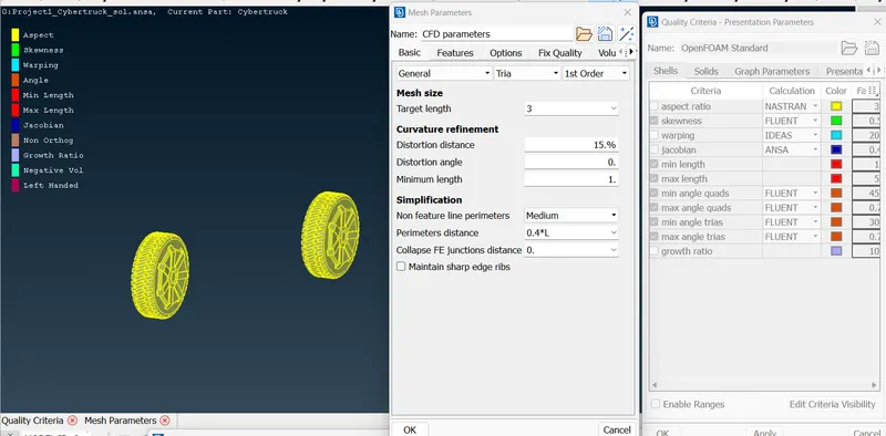
Setting perimeter and macros to 3 mm.
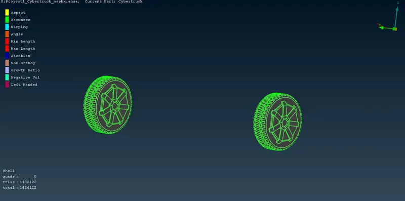
After meshing and removing all the off elements using Reconstruct and other improve tools:
(b) Windows:
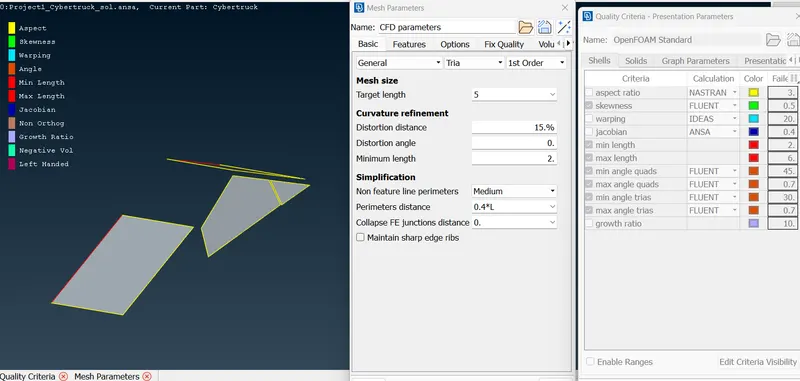
Setting perimeter and macros to 5 mm.
After meshing:
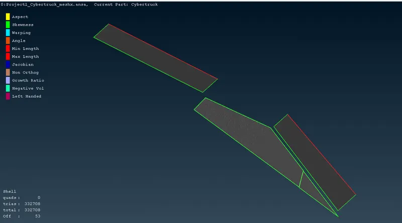
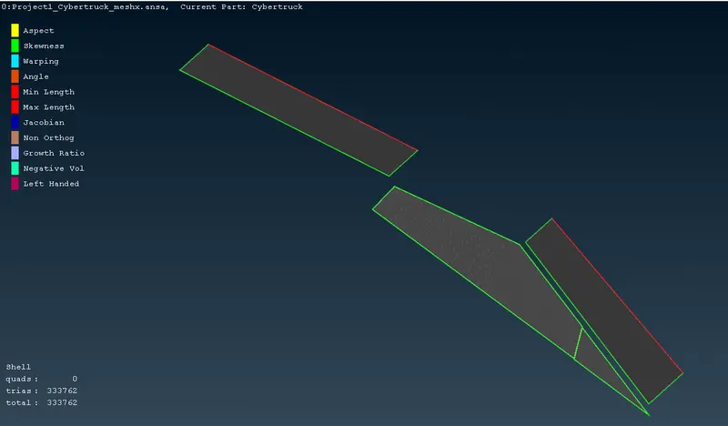
After meshing and removing all the off elements using Reconstruct and other improve tools:
(c) Lights:
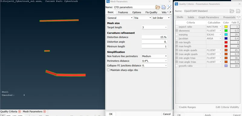
Setting perimeter and macros to 3 mm.
After spot meshing:
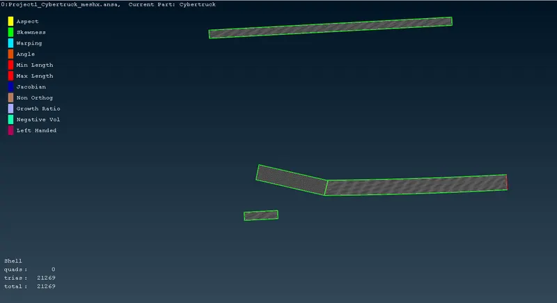
The car body is meshed at the last to avoid deletion of mesh from the other connected PIDs.
To resolve this problem we will remove the common cons when selection length>perimeters.This will isolate the already meshed PIDs from the body.
(d) Car Body:
The minimum length taken for other PIDs in contact with the car body is 1mm, thus the minimum length will be 1 mm.
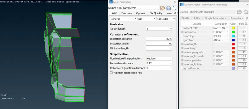
Isolating meshed surfaces:
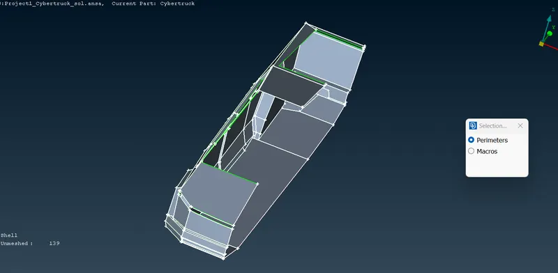
Setting perimeter and macros to 4 mm.
Spot Meshing:
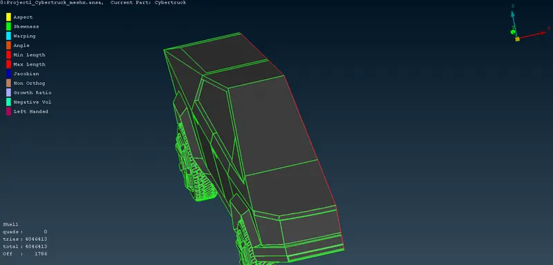
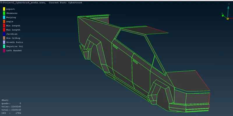
After using reconstruct and improve tools:
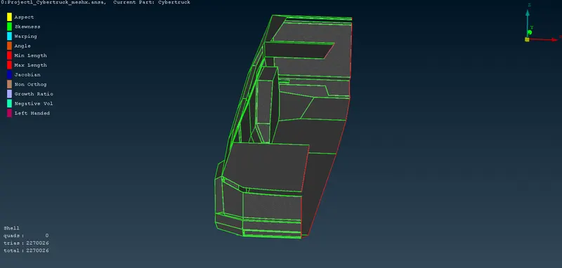
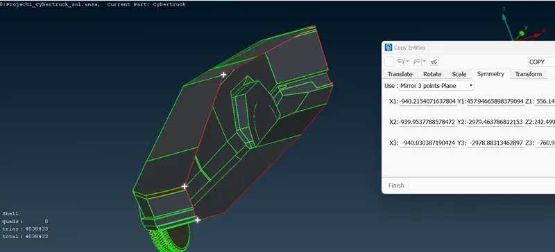
4. Complete the car body using Transform>Copy>Symmetry tool
Finished total car mesh after removing errors:
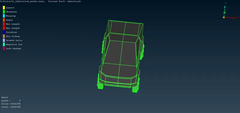
Measuring the length of the car:
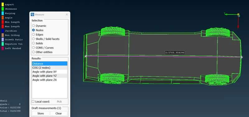
L=5790 mm (Approx.)
Wind Tunnel Dimension:
- The distance of the wind tunnel's front face from the front of the car should be 4L and wind tunnel's rear face from rear it is 6L.
- Bottom face of the wind tunnel is taken near the wheels as we need cfd results for the top surface of car.
- The top face of wind tunnel is at 3L distance from roof of CAR.
- The width is assigned as L distanace on each side from the car sides.
Creating wind tunnel:
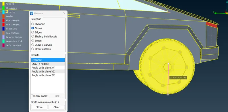
- Create a point near the rims and tires using Points>Relative tool from one end of car bottom.
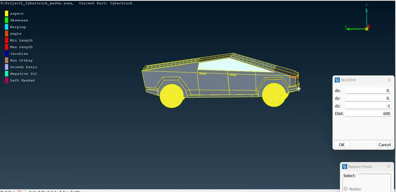
- Take the above point as reference and create another point in +ve x-axis at 4L=4*5790=23160 mm.
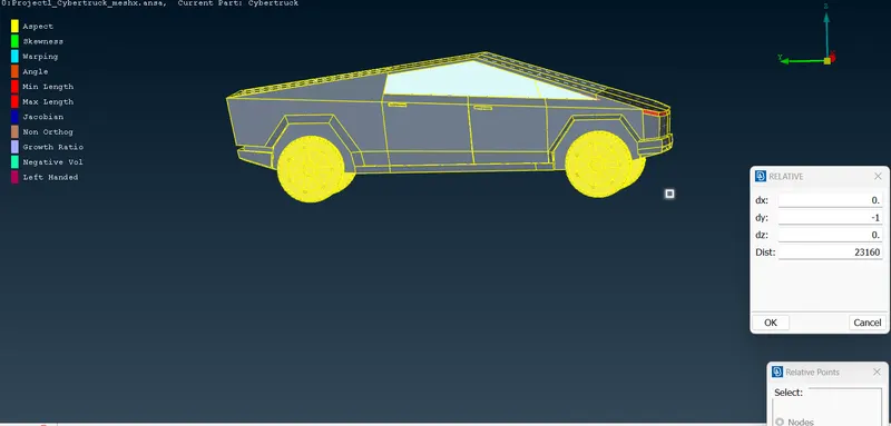
- Measure the dimensions from the refrence point of the car to rear of the car:
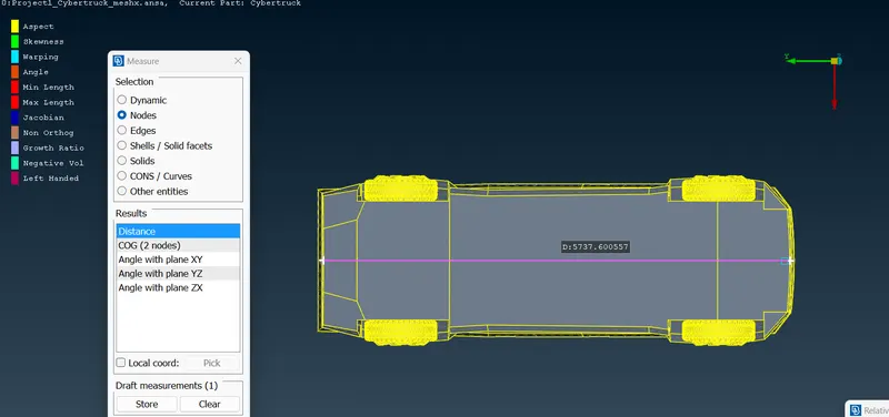
X=5738 mm
- Take another point behind the trunk using refrence point at 6L+X=6*5790+5738=40478 mm
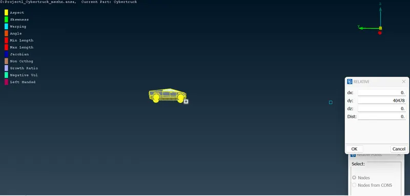
- Using the refrence points far from the rear and front of the car, create points for the width of the wind tunnel at L=5790 mm on each side.
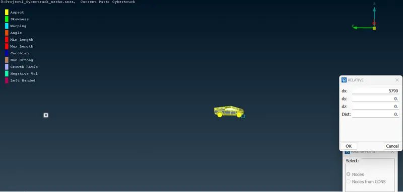
+
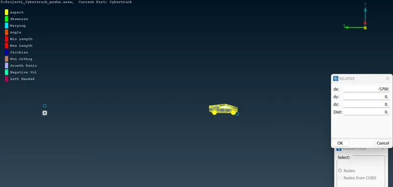
=
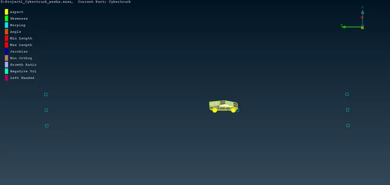
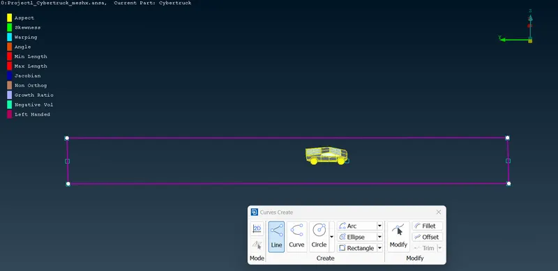
- Now use curve option to create a outline using the created points and then create a surface by using Faces>New>fitted tool:
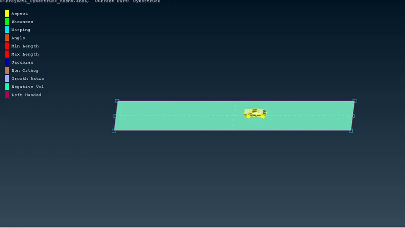
Assign new PID for the surface.
- Measure the vertical height from the car roof to created bottom surface of the wind tunnel.
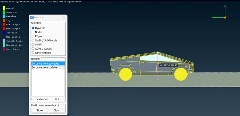
Y=1927 mm (approx.)
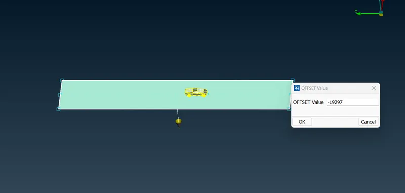
- Use Faces>Offset>face tool to create top surface of wind tunnel at 3L+Y= 3*5790+1927=19297 mm.
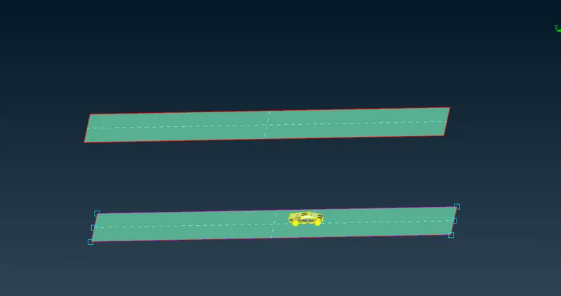
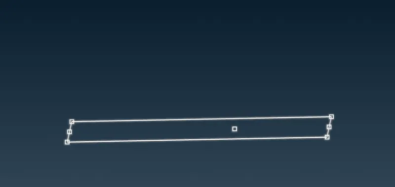
- Delete all the hot points and curves created to make bottom surface using delete tool:
- Now using Faces>New>Coons tool to create remaining surfaces of wind tunnel and assign PID names for each surface.
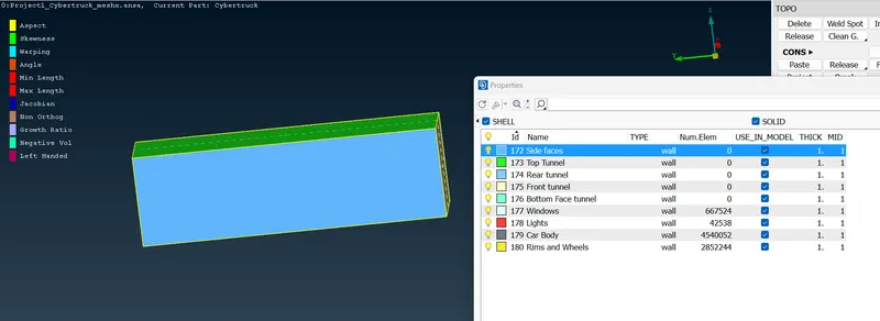
MESHING THE WIND TUNNEL:
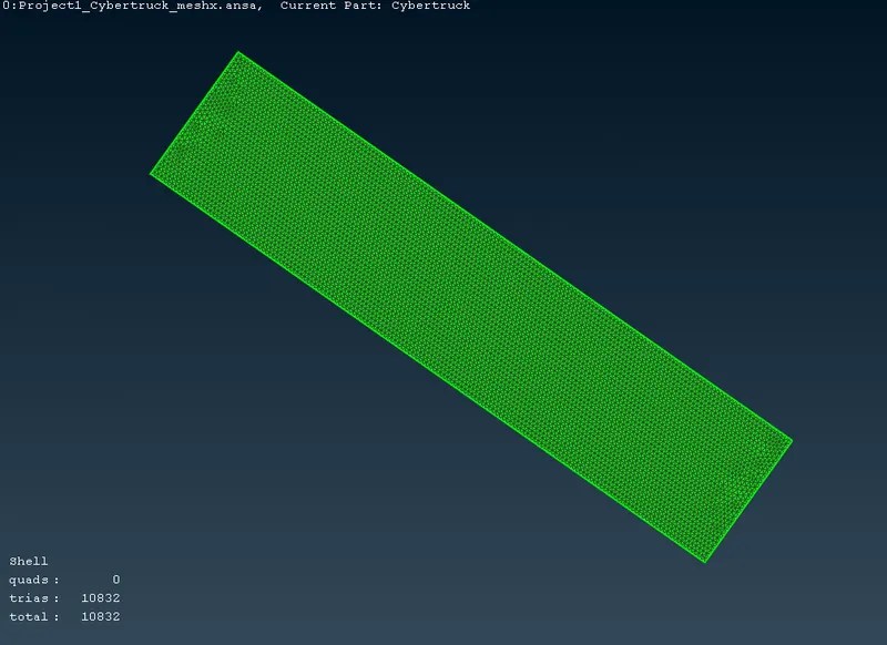
- The top surface is to be meshed with perimeter set to 400 and macros value as 400.
- Bottom surface is meshed with perimeter and macros values set to 120 as it is going to provide cfd data.
- As the mesh length is varying from bottom to top surface from 120 mm to 400 mm, Mesh>Perimeter>Spacing>Geometric tool is used with Dstart=120 and Dlimit=400 with factor of 1.1.
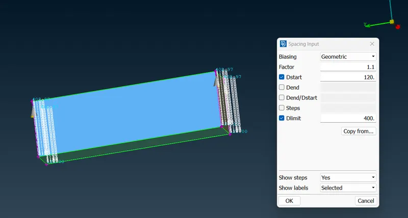
- Meshing bottom surface:
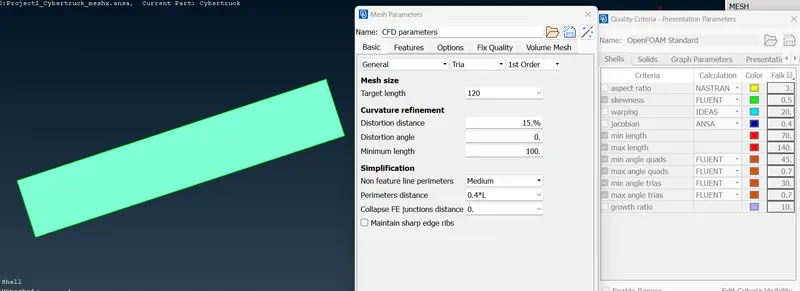
Meshed bottom surface:
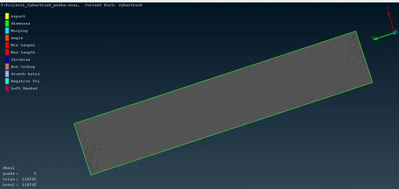
- Meshing Top surface:
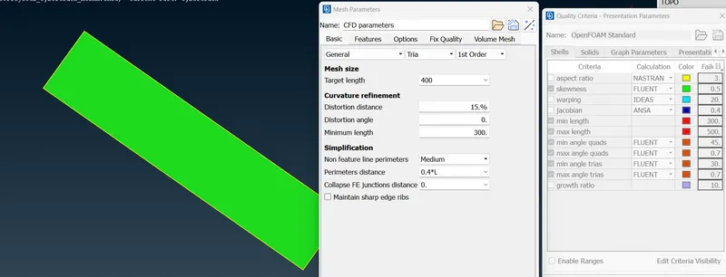
Meshed top surface:
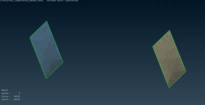
Meshing front and rear surface:
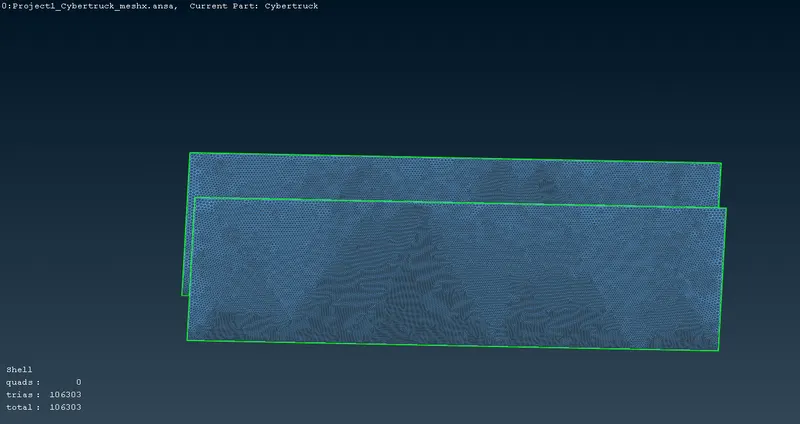
Using spot mesh tool mesh the remaining side surfaces:
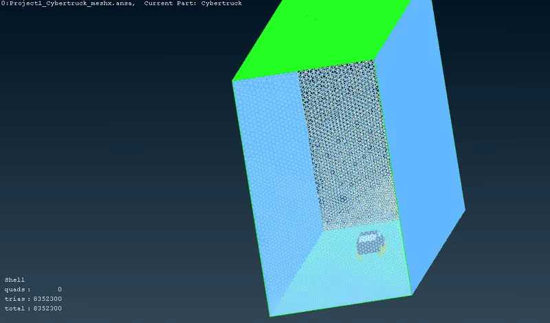
Final mesh:
VOLUMETRIC MESH:
- Different volumes detected using Volume>define tool:
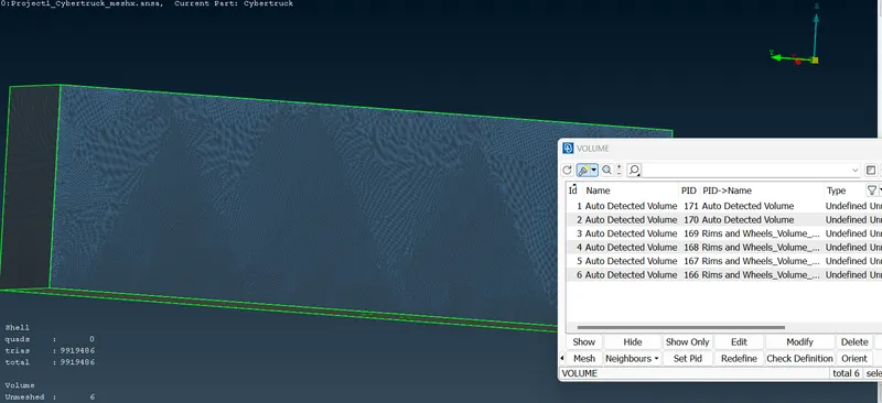
- Delecting the unnecessary volumes:
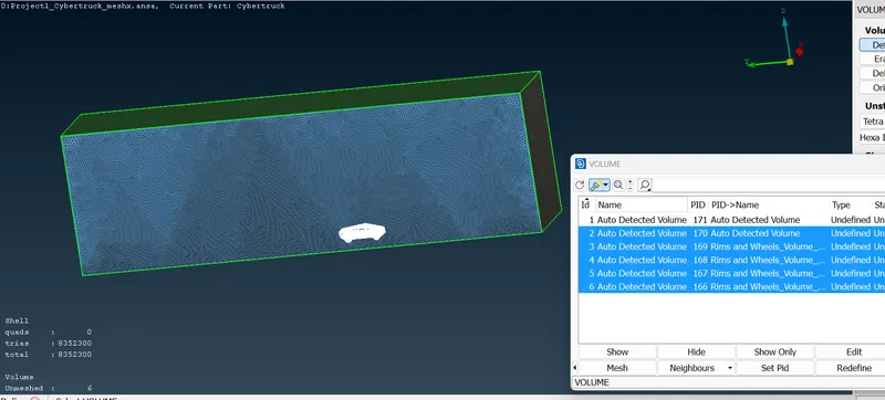
- The single volume present:
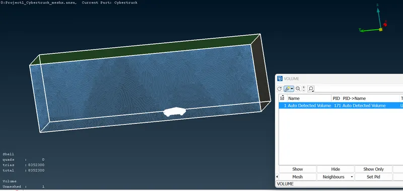
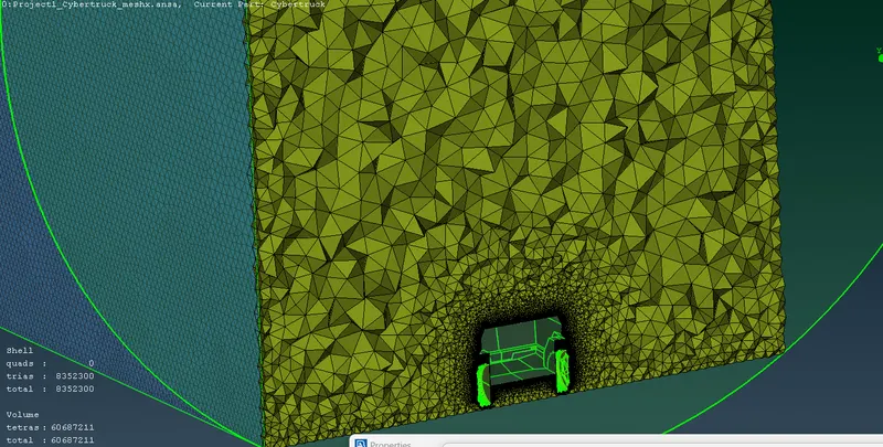
- Mesh the whole selection in V.Mesh mode.
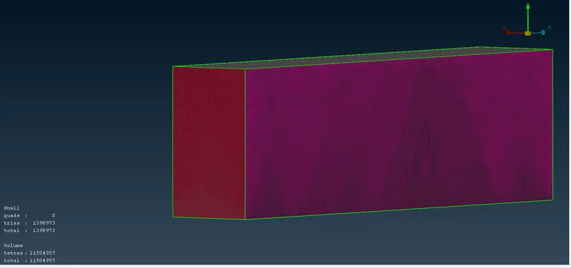
- Use cut XZ plane to view the tetra mesh.
------------------------------------------------------------------------------------------------------------------------------
- As the mesh length for the car body taken smaller, mesh elements are more in numbers.
- Increasing mesh length will result in decrease in meshing time and less memory is consumed.
- Cuting the model in half reduces mesh timing and helps to do geometrical cleanup more easily.
- Using different tools like reconstruct, quality checks,rehape and move tool helps to reduce and eliminate off elements more easily.
- Volumeric meshing failed several times when the bottom face was meshed with mesh length below 120 due to large memory usage and system failure.
- Increase in the mesh length helped in reducing volumetric mesh timing.
------------------------------------------------------------------------------------------------------------------------------
CONCLUSION:
- All geometrical errors were solved using half symmetrical model of the the given car after cutting the model using cut and delete tool and meshed with different appropriate target lengths and achived good quality triangular mesh.
- Off Elements=0 for surface mesh of the tesla car.
- Created wind tunnel succesfully and meshed it properly.
- Performed tetra V.mesh after eliminating unnecessary volumes succesfully.
------------------------------------------------------------------------------------------------------------------------------
G. Drive File:
https://drive.google.com/file/d/1sB0P_N7G5IHvfWKouSnNU4a3A9uyBvlT/view?usp=sharing