Week 3 Challenge : CFD meshing on Turbocharger
TOOLS USED:
1. TOPO toolbar: Helps in fixing the topology of the model.
- Insert:It creates hot points on cons or 3d curves.
- Topo: This function automatically creates topological conditions between selected adjacent CONS.
- Project: It defines a new hot points or new cons as the projection of existing hotpoints or cons.
- Parametrical: Defines new nodes or hot points on cons parmetrically.
- Cut: splits or joins existing faces.
- Intersect: Used to define the intersection between two surfaces penetrating each other.
- Create new surface
- Coons: This is an easy way to define a new surface by its boundary curves.
- Fitted: The FITTED option is used for the definition of a non-planar Face. The created Face fits to the selected boundaries.
- Fine: It increases or decreases the presentation resolution of a selected 3D-curve, CONS segment or Face.
2. Mesh toolbar
- Length: Helps in setting the element length on selected perimeters or macros.
- Spot mesh: It creates automatic mesh for macro and finite element shell mesh areas by using special meshing method for macro areas and gives better result than free mesh in case of weld joints.
3.Volume mesh:
- Define: Defines multiple volumes already surface meshed automatically.
- List: Enables handling of defined volume present in the database.
- Tetra CFD: It is suited for geometries with thick voluemes and large domain for CFD purpose.
4. Set PID: This function assigns selected Faces, Shells or Groups of entities to an existing or new PID.
5.Delete: The delete option is used to delete all the entities which are selected.
6. Loop: Helps to select multiple cons connected to each other at a time.
7. Fill Holes: Fills the holes and holes present in the model.
8. Compress: Compress files size by removing unwanted and unused entities.
9.Wire: To see model in wire frame mode.
10.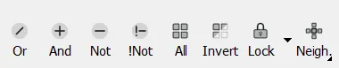 These tools are used to see entities or hide entities and are very useful while inspecting then model for errors.
11.Cross-Hatches: Activate and deactivate cross hatches on the model surfaces.
12.PID properties: It is helpful to name the PIDs present in the model and facilitates property management.
AIM:
To perform surface mesh with the given lengths as per PIDS after checking and cleaning geometrical errors in the given model. Then performing volumetric mesh.
Solution:
Given Model: Turbo charger
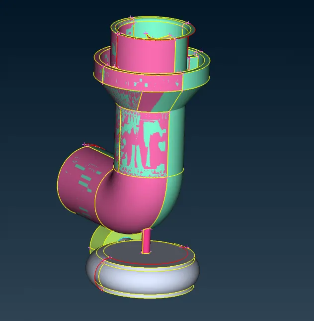
Different coloured surface means ovelapping of more than one surface in the model.
STAGE1:
Deleting the extra surfaces:
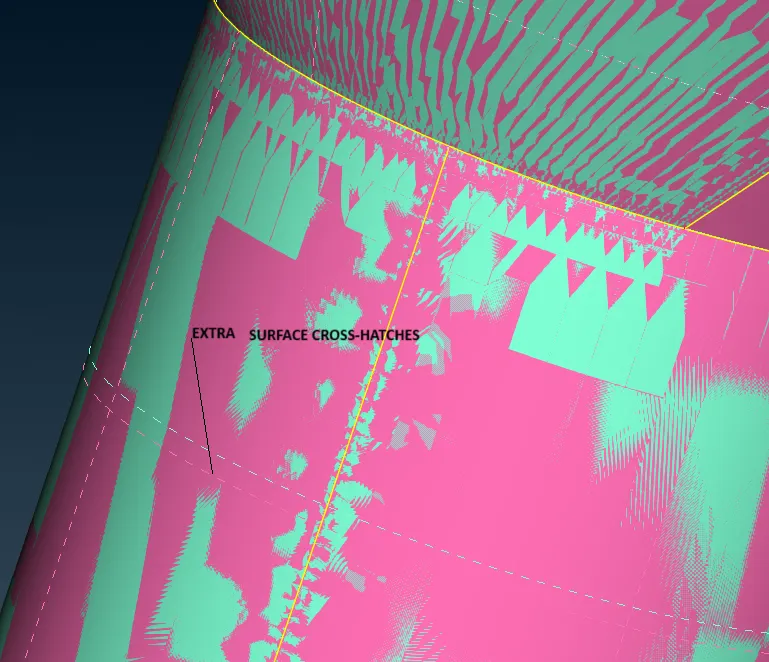
(a) Enable cross hatches to select the unwanted surface in the model and remove the surface using the delete tool using PID region for selecting whole surface.
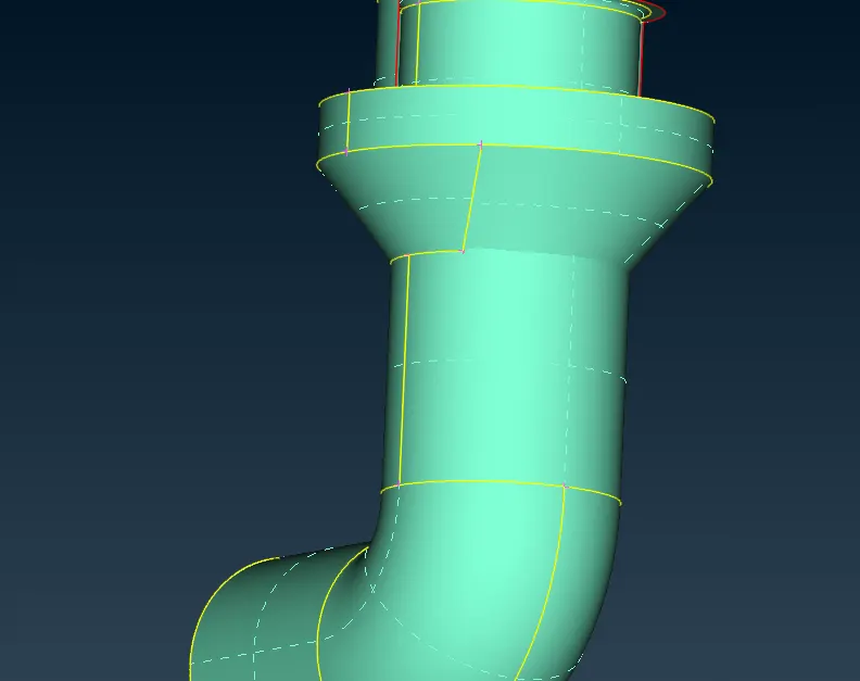
After removing extra surface:
(b) In the below figure we can see extra surface extending,
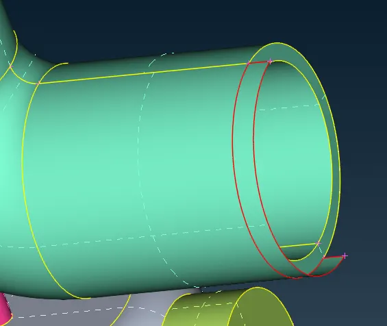
To fix this, remove the surface by using delete tool and selecting the surface using ENT tool.
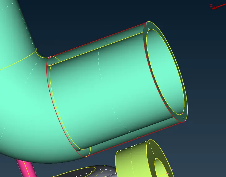
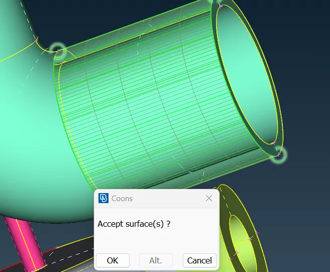
Now use, TOPO>Faces>New>COONS to fix the surface using the single cons.
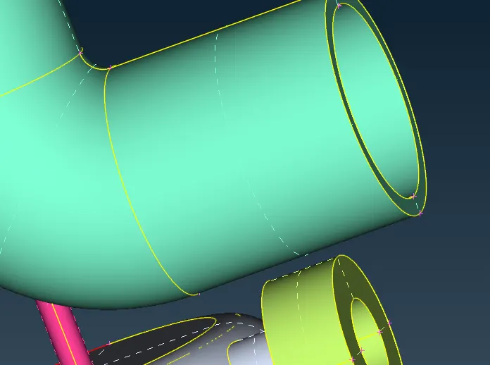
Fixed surface:
(c) The next part to fix is the single con found in the below figure
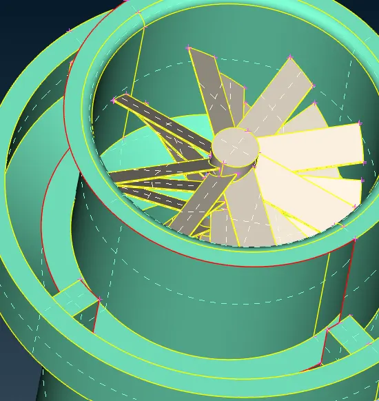
First create smaller surfaces to get more accurate surface as directly using COONS tool is not possible.
To create smaller surface, create new hot points from the existing hot points using multiproject tool
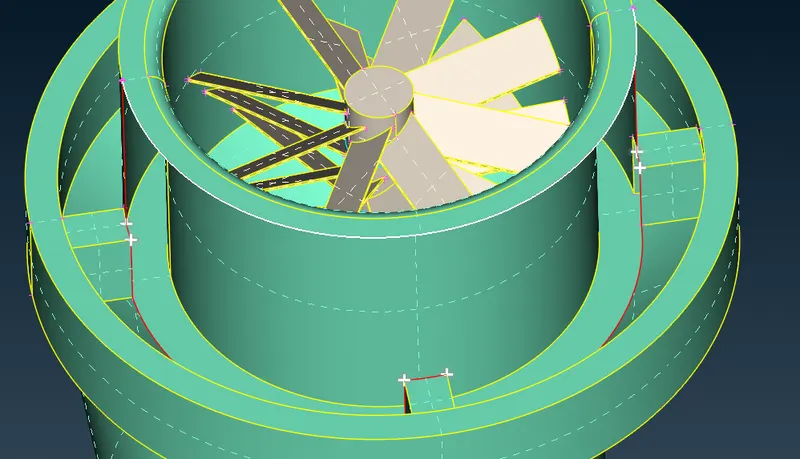
New hot points projected on the selected single con:
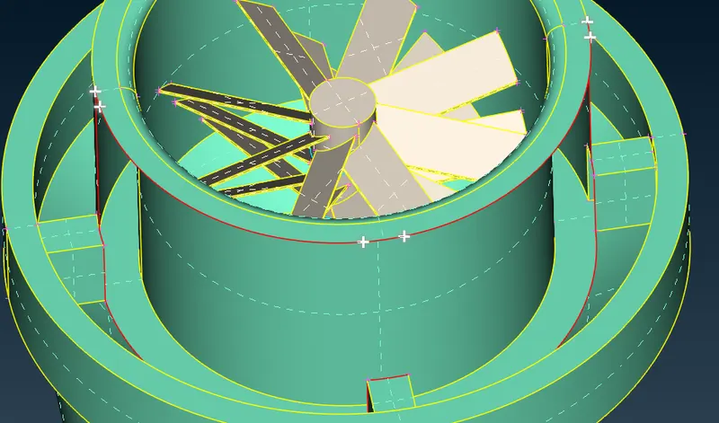
Using these hot points create 3 smaller surfaces were created using TOPO>Faces>New>COONS:
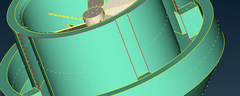
Now the gap between these newly formed surface can be filled using one by one using TOPO>Faces>New>COONS and selecting all the single cons available using loop tool:
suggested surface:
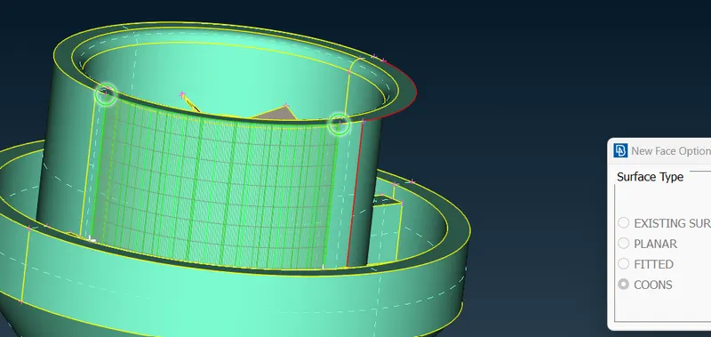
New surface generated
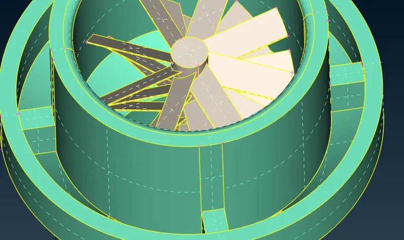
Checking for other problems in the model:
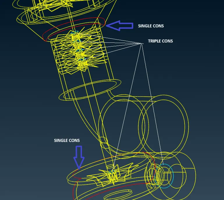
(d) Fixing the single cons first:
By using the boolean tools NOT(-) and AND (+) tools model was opened to see the single cons that are needed to be rectified.
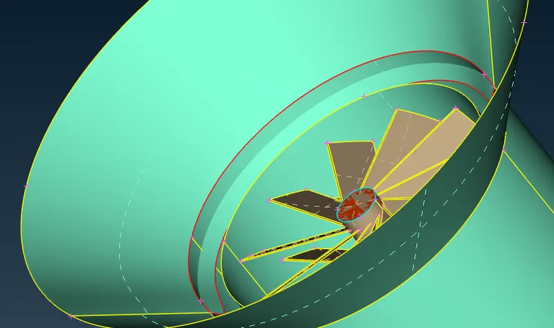
In the above figure we found that the single cons are present due to two surfaces intersecting each other.
To remove the unwanted part we will use Intersect tool TOPO>Faces>Intersect and Delete tool.
one of the two intersecting surface is selected and then middle clicked to select the second intersecting surface.
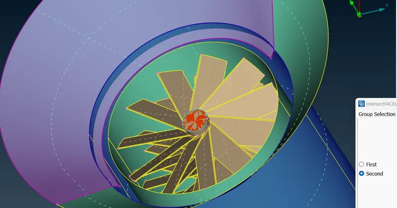
By using the delete tool the unwanted surfaces are removed:
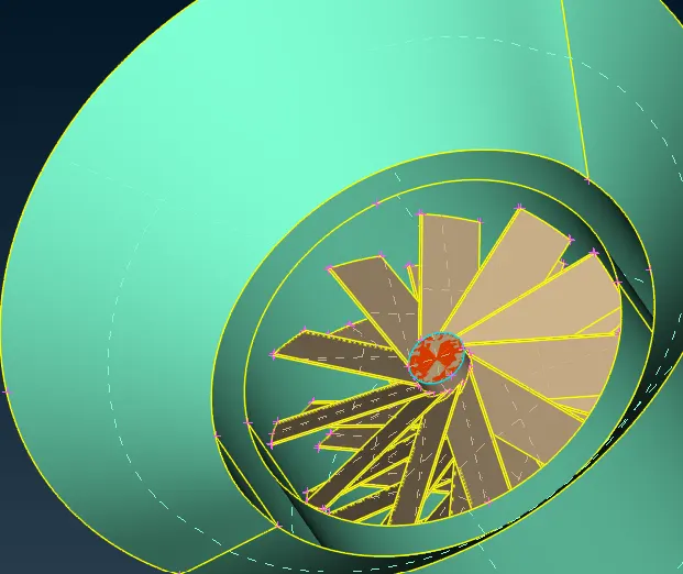
As per the above figure it was found that there are multiple surfaces as the colors are distorted. To fix such surface we will use Delete tool to remove the unwanted surface by selecting cross-hatches.
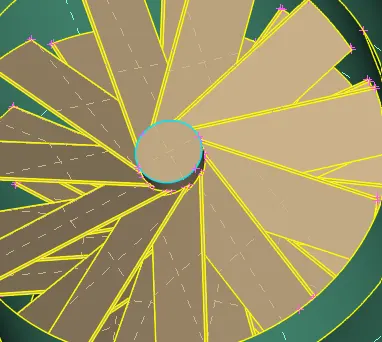
There is a blue coloured con, as there are only two surfaces in contact we cannot have triple cons. Thus we will use Release tool to make it set of single con
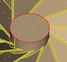
These single cons can be fixed using Topo tool which combines single cons to double con
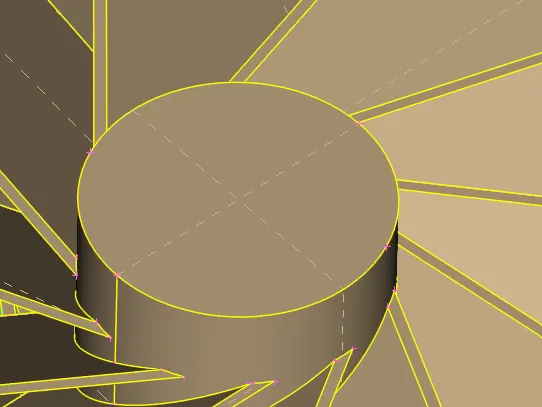
Now fixing the bottom part of the turbocharger:
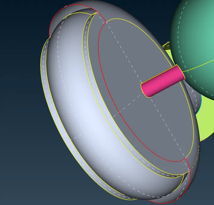
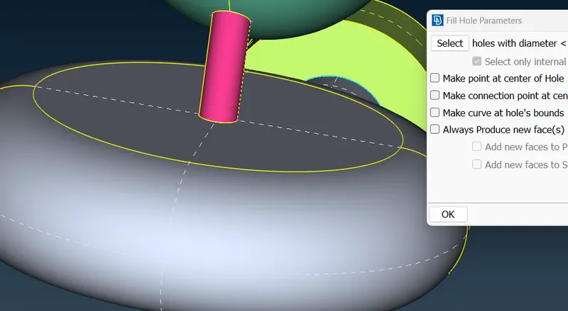
New faces options didn't provides good fix but using fill hole gave a perfect surface.
(e) Now fixing the upper blade triple cons:
Use NOT tool to see inspect the surface where triple con is present.
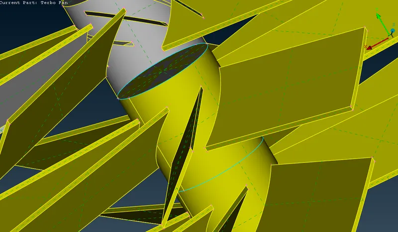
Two surfaces can be seen which are not required. By using delete tool, these surfaces are removed.
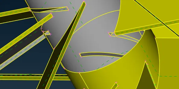
Similiarly, again use NOT tool to inspect the next triple con properly.
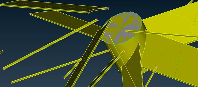
Use DELETE tool to remove the ovelapping surfaces.
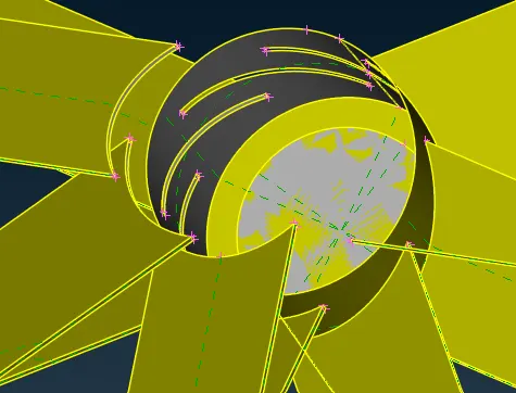
Similarly, removing all the triple cons and making the blades shaft a signle piece.
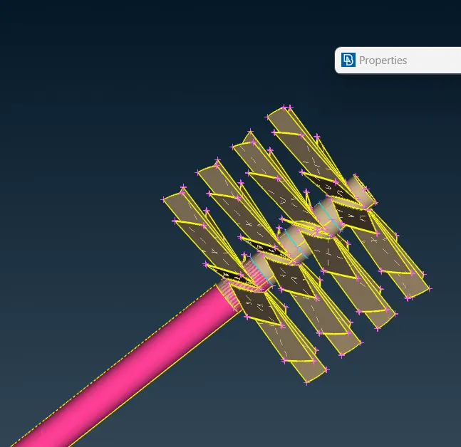
Using DELETE tool:
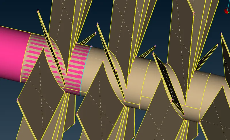
The left over triple con is the result of the over lapping two PIDs. It is needed to be deleted but to do so the overlappig surface is needed to be separated. So, we will use Project tool to put a cut over the unwanted surface.
Toppo>Cons>Project
Use loop tool to select and project the selected part on the lower shaft(pink coloured PID)
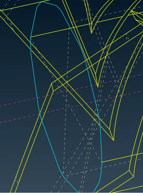
The cut is uneven.
Fine tool is used to smoothen the surface.
TOPO>Auxillary>Fine
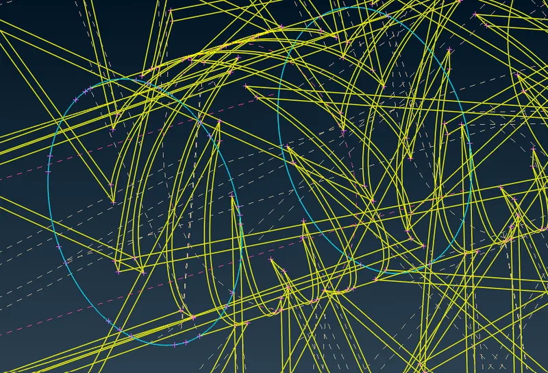
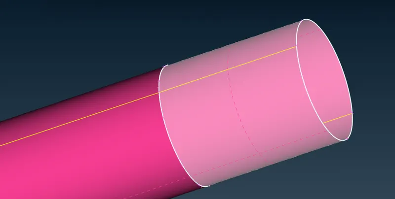
Now, with Delete tool the extra overlapping surface is deleted.
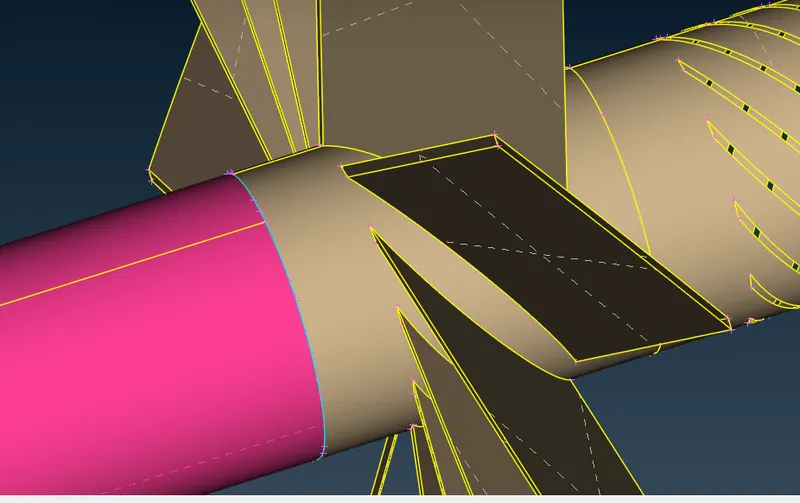 +
+
There is a triple con present. By further checking a third surface was found.
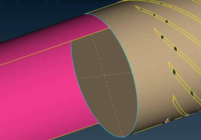
By using delete tool, the surface was removed to eliminate unwanted triple con.
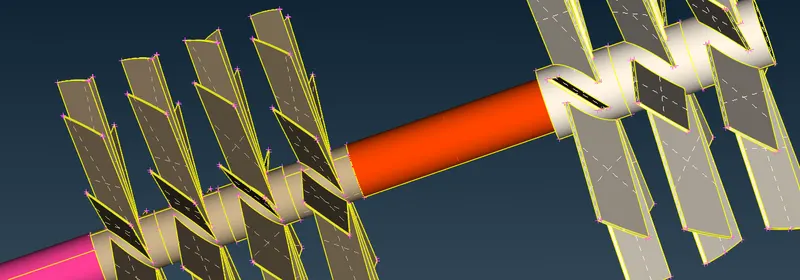
In the below figure there is a triple con present:
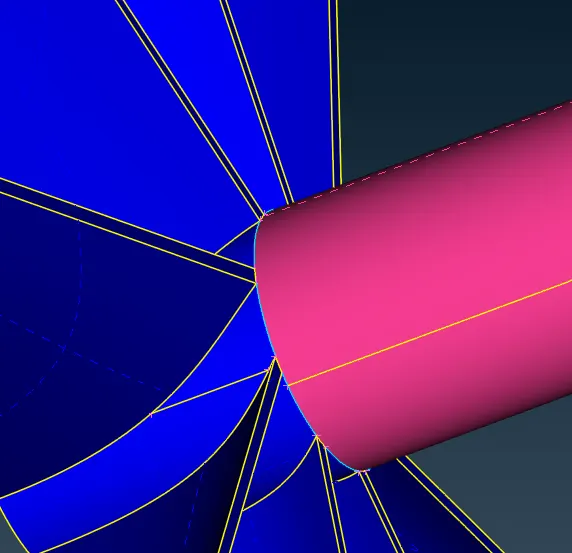
(f) After closely looking into the model it was found that there is a overlaping surface also.
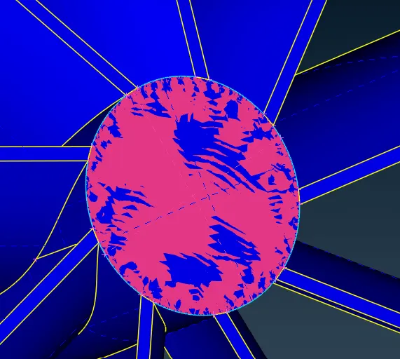
Deleting the overlapping surface using DELETE tool.

Still the triple con is there because the blade surface, the shaft surface and the crossectional area of blade are in contact.
To delete the crossectional area is needed to be separated from blades.
Using Cut tool in Faces to separate the surface.
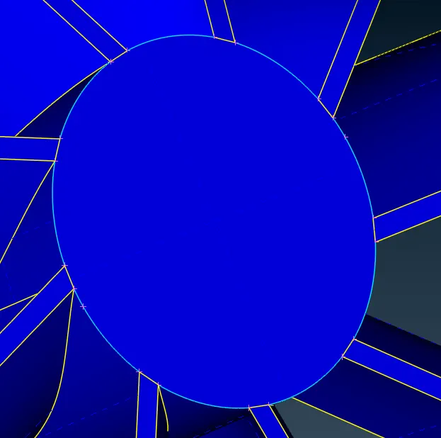
Now use Delete Tool to remove the surface.
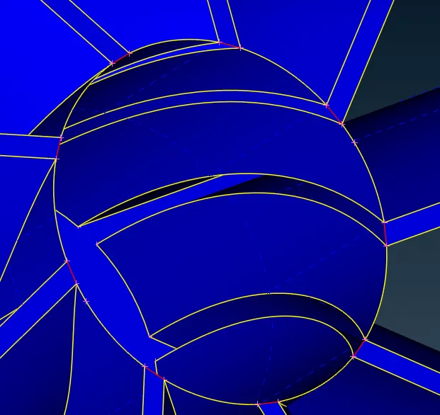
Now use Topo tool to convert all the single cons to double cons using the shaft.
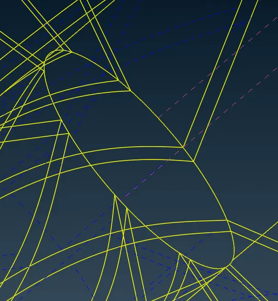
(g) The shaft should be a single volume:
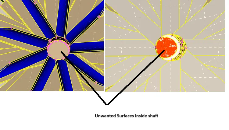
Deleting these surfaces to make single volume shaft:
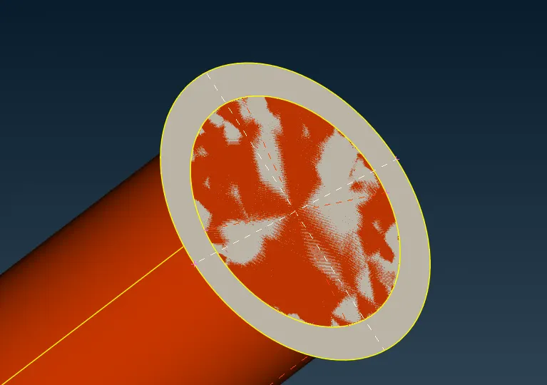
For the above surface we will use Project tool to cut the inner circle from the red coloured PID.
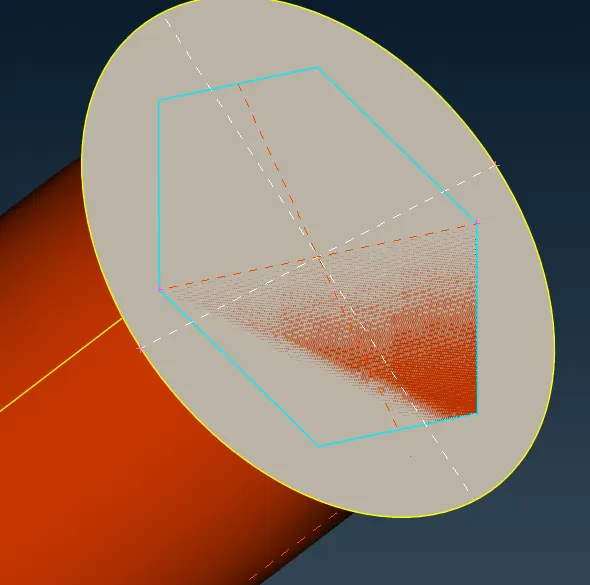
Using Finbe tool to reshape the shaft
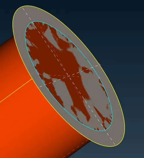
Now using Delete tool, deleting unwanted surfaces.
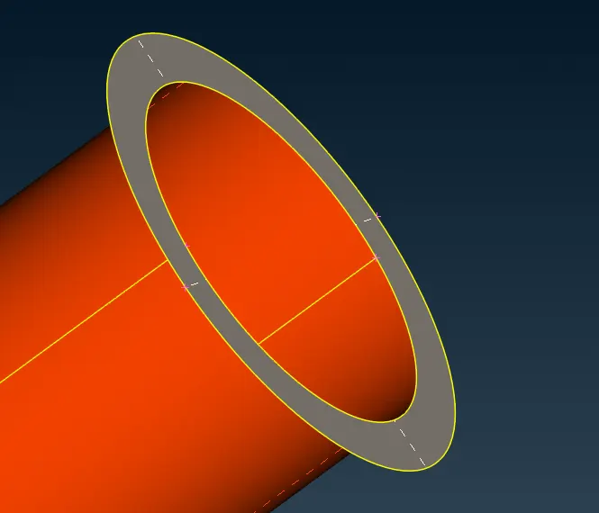
Now removing the lower shaft unwanted surface:
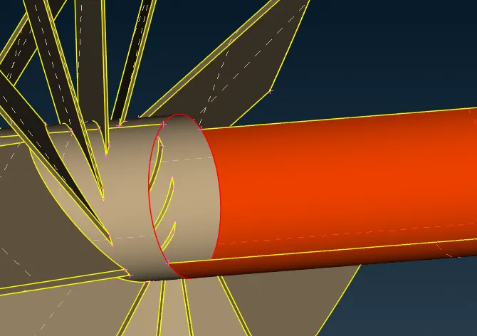
Removing the surface producing single con.
Using Topo it is fixed:
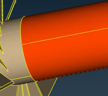
Using Not tool on the top of shaft we can see if the shaft is a single volume or not:
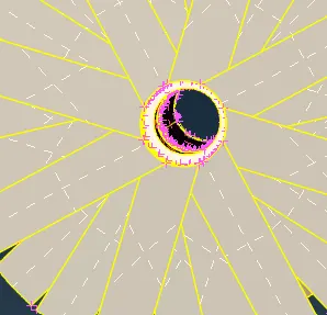
As we can see the bottom, thus the shaft is a single volume.
Inspecting for errors in topology of model:
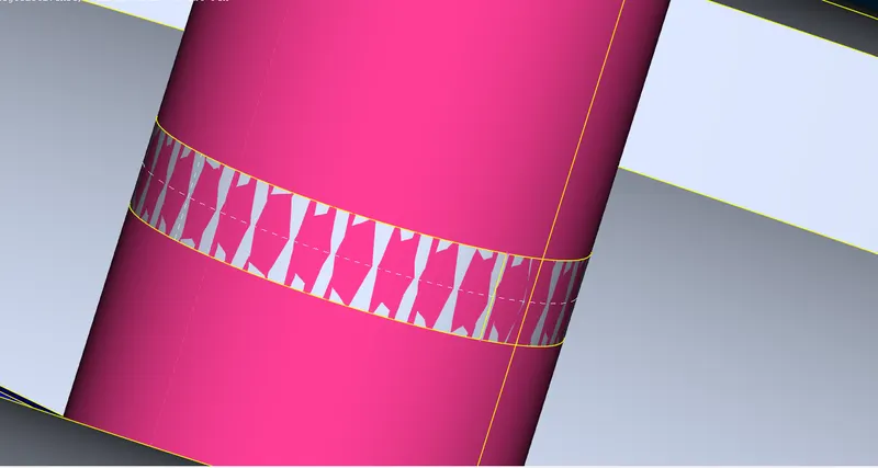
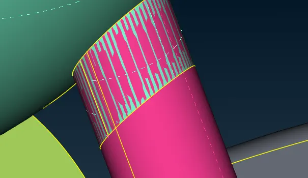
This can be eliminated by simply using DELETE tool.
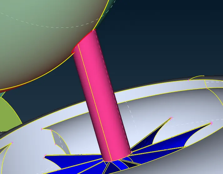
After eliminating the overlapping surface, single cons are left.
It is removed by using Project tool on the shaft and the using Auxillaries>Fine tool.
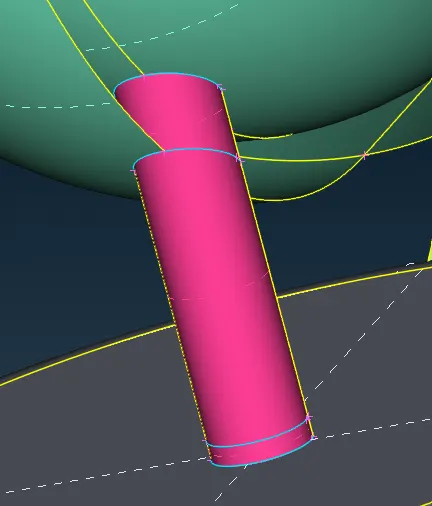
Inspecting other errors:
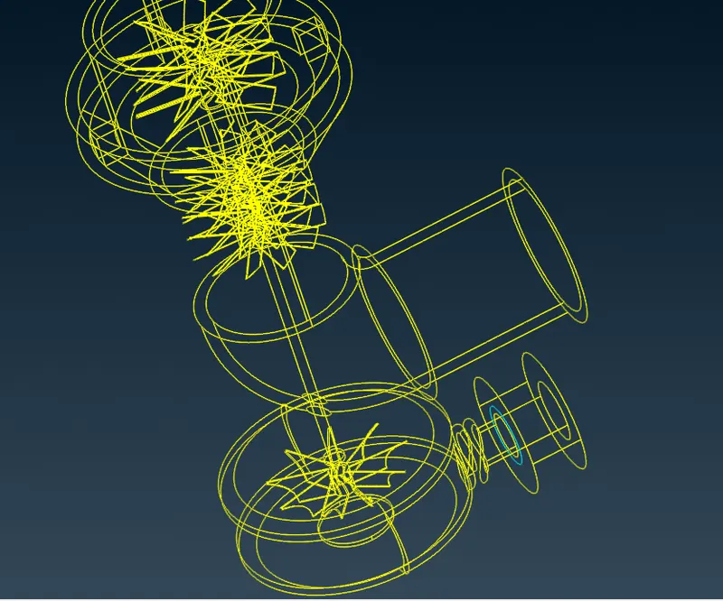
In the wireframe mode it was found that a triple con is present but it shares 3 surfaces. Thus, it is not an errror.
STAGE 2:
CLOSING THE MODEL:
Using Topo>New>COONS
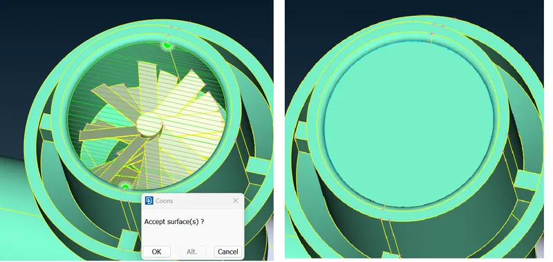
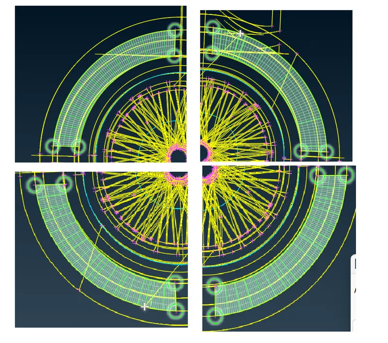
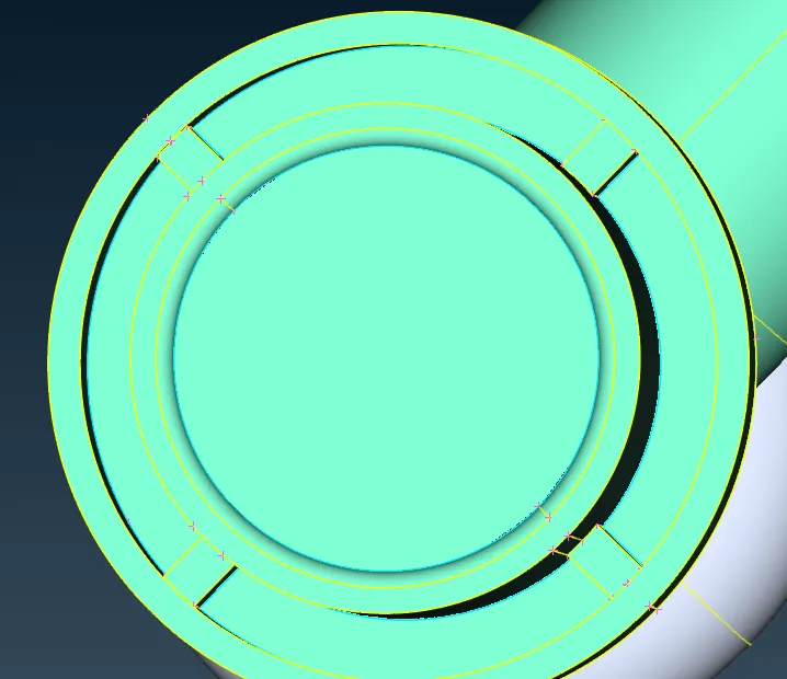
Using Topo>New>Fitted
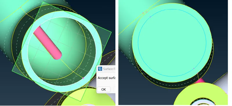
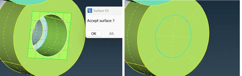
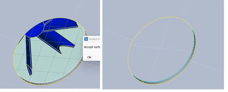
STAGE 3:
PID NAMING:
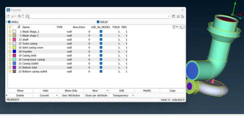
STAGE 4:
SURFACE MESHING:
Given target lengths
- Blade stage-1 = 1 mm
- Blade stage-2 = 1 mm
- Impeller = 2 mm
- Shaft rotor = 1 mm
- Turbo casing = 5 mm
- Compressor casing = 5 mm
- Inlet casing cover = 5 mm
As per the challnge Inlet casing cover and compressor casing have 5 mm target length.
Selecting these PIDs from PID manager.
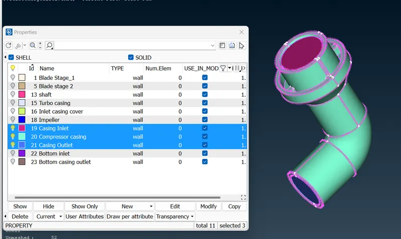
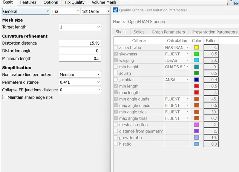
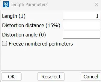
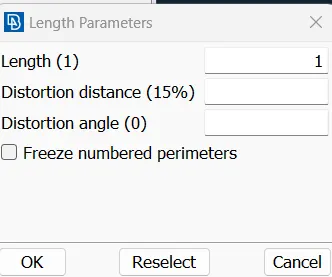
Setting target length to 5 mm and changing the quality parameters using MESH>Perimeters>Length for perimeters and Macros.
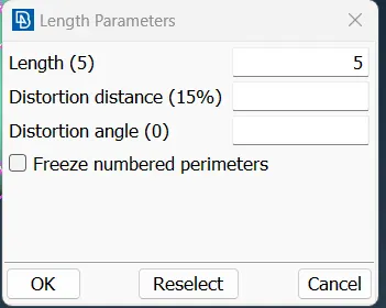
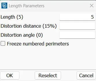
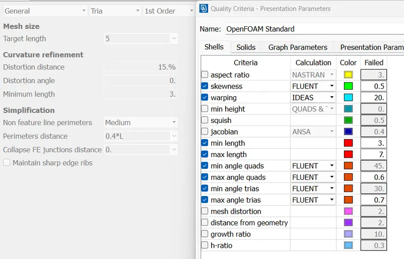
Now, meshing the selected component using Mesh>mesh Generation>Spot mesh
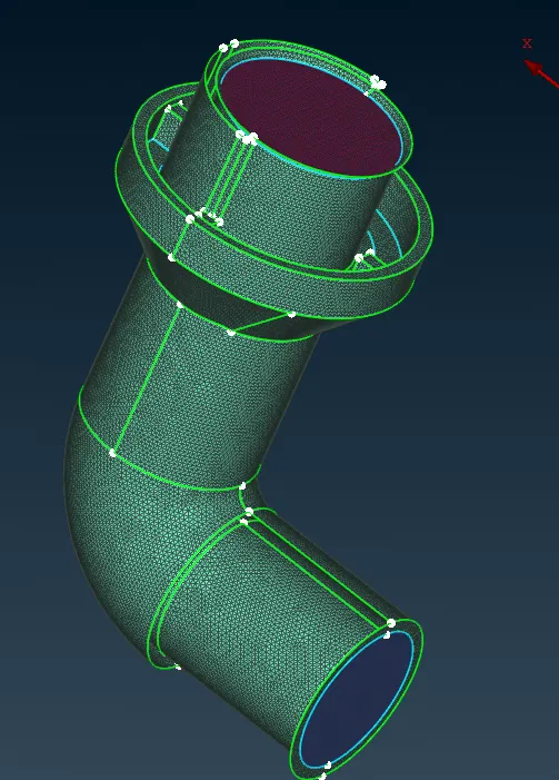
Similarly, meshing turbo casing with same settings:
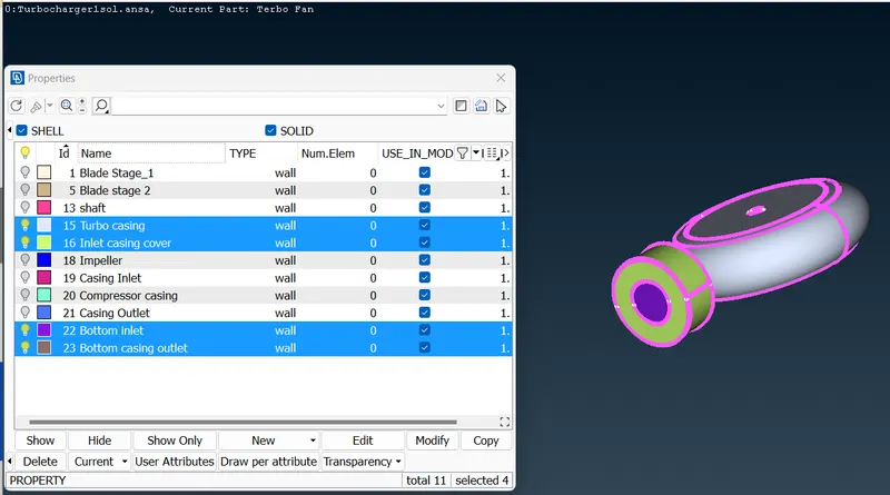
Meshed Turbo casing:
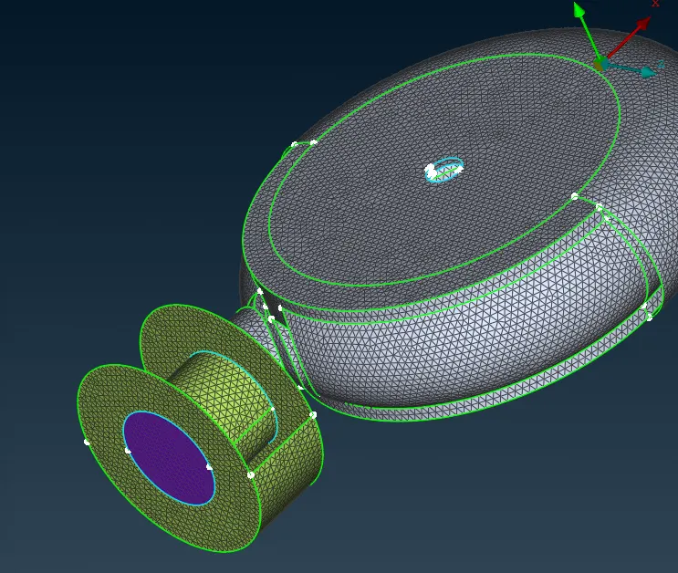
Now meshing Impeller with 2mm target length:
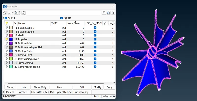
Changing the settings of mesh and quality parameter:
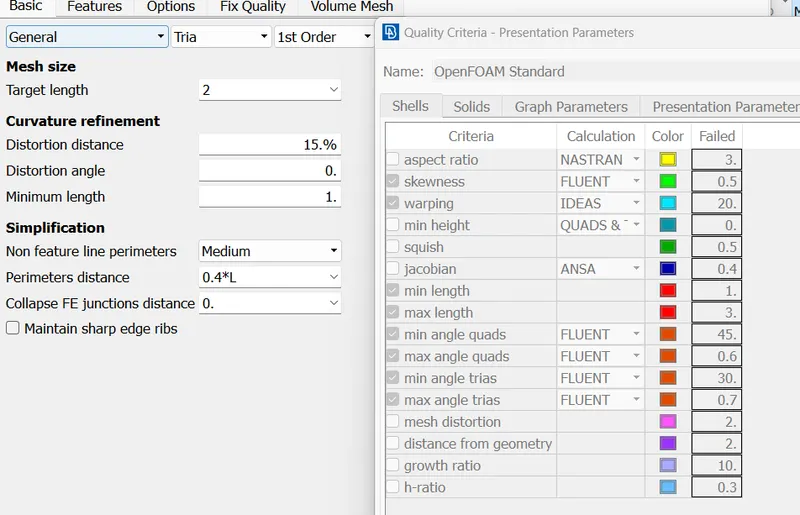
Perimeters and macros setting:
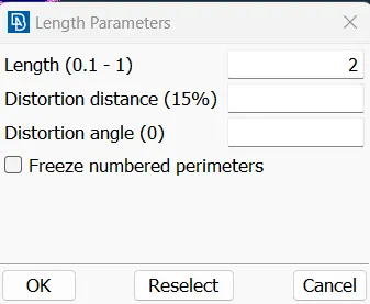
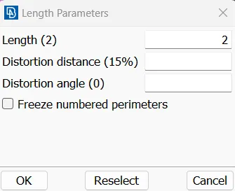
Using Spot mesh:
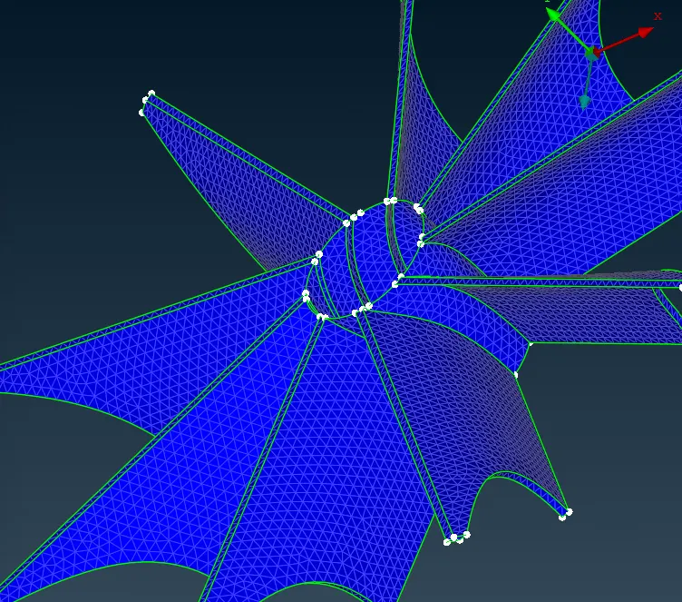
Meshed Blade stage-1, Blade stage-2 and rotor shaft using MESH>Mesh Generation>Spot mesh
Meshed Blade stage-1, Blade stage-2 and rotor shaft :
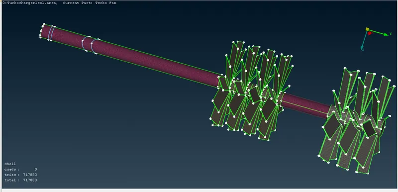
After meshing due to conflict in the meshing parameter some of the meshing got deleted.
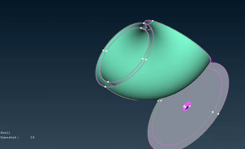
Re-meshing these components:
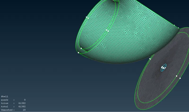
Again meshing the remaining component as impellar some parts are unmeshed:
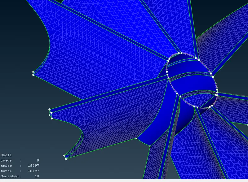
At 2mm mesh length:
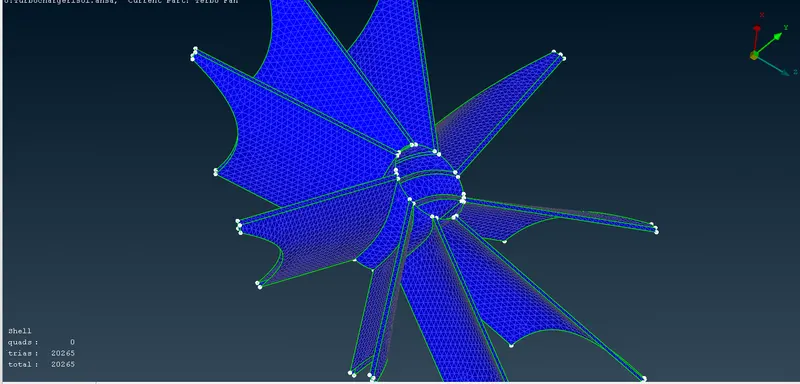
Final Surface mesh:
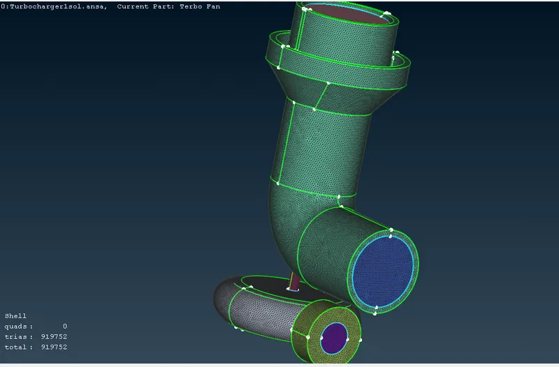
Now use Mesh>Macros>cut tool to smoothen the mesh around the joints as per requirement.
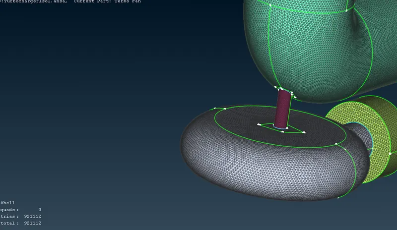
As there are no unmeshed surfaces, we can proceed for volumetric mesh.
STAGE 5:
VOLUMETRIC MESHING:
Go to
V.Mesh>Volumes>Define
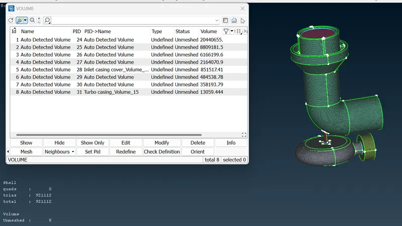
Deleting the unwanted volumes as they represent the thicknesss of the models and fluid can't flow through them:
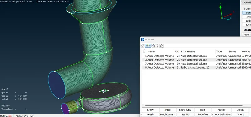
Now remeshing the remaining components with Tetra CFD elements:
V.mesh>Unstructured Mesh>Tetra CFD
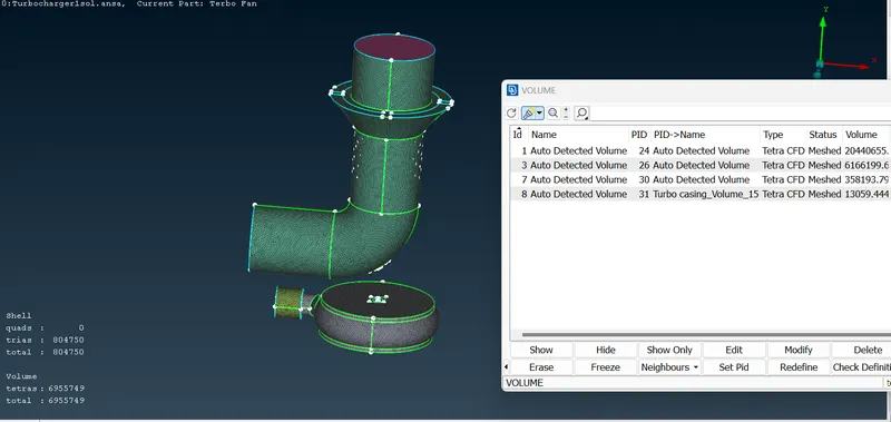
Final Volumes of the components required:
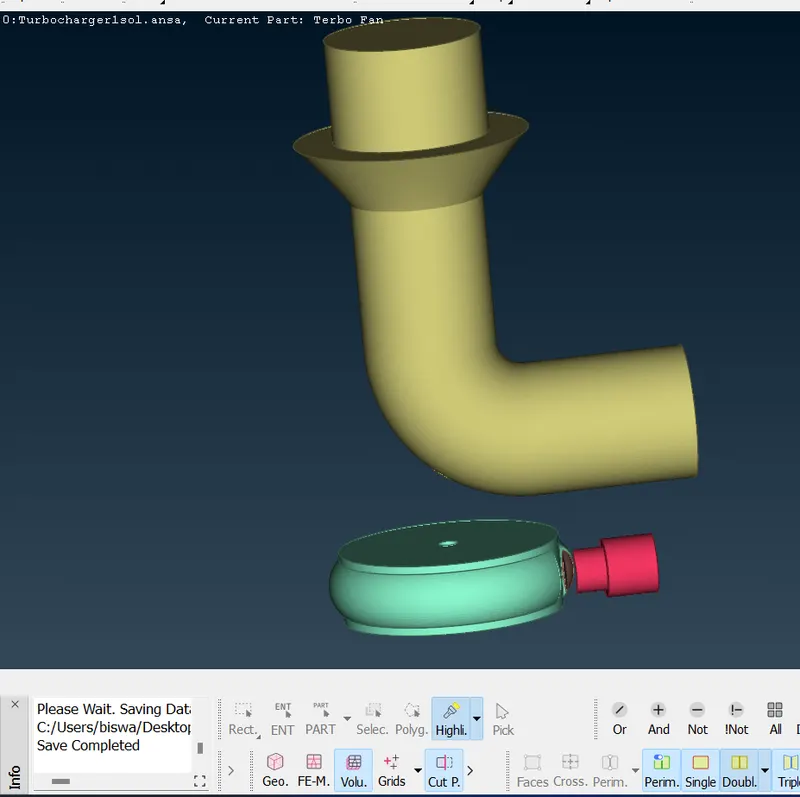
Volumentric tetra mesh:
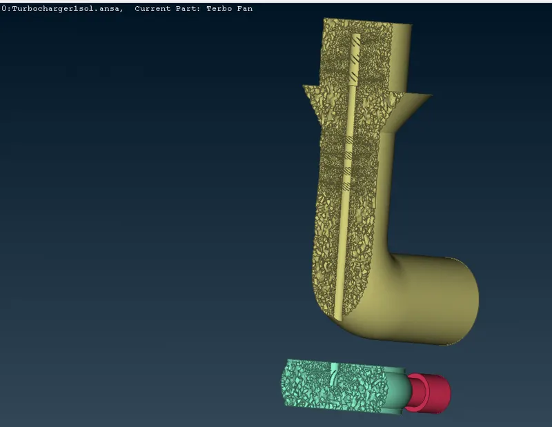
Removing all the geometrical errors,rechecking and surface meshing the model part by part showed how to cleanup the model efficiently using different tools. Finally, got the volumetric mesh which can be used in CFD.
CONCLUSION:
- The given model was inpected and all the geometrical errors were fixed.
- The model was surface meshed using the given target lengths as per PIDs.
- After removing unnecessary volumes, tetra cfd meshing was done on the model successfuly.
FILE LINK:
https://drive.google.com/file/d/1s80k2XhAS-BpK6Yt0_SqwGOgIGG8NP7Y/view?usp=sharing