Project 1 : CFD Meshing for Tesla Cyber Truck
Aim:
Check and solve all geometrical errors and assign appropriate PIDs. Perform meshing.
Objective:
To practice on checking geometrical error, doing PIDs, learn about surface mesh, how to perform symmetry and how to make wind tunnel.
Body of content
Step 1
Insert Model
File
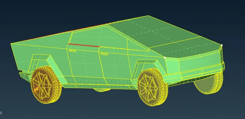
Step 2
Mesh < Length < Perimeter as 1
Mesh < Length < Macros as 1
This help as to bring perfect size and shape of each and every component of Tesle cyber truck.
Step 3
Removing tripple and single cons from the truck.
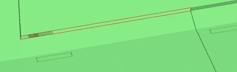
Creating missing surface
Step 4
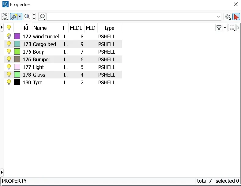
Applying PIDs
Properties < PID name (right click) < Select the object < Middle click
Apply to all the parts
Step 5
Meshing of Geometry
Classic mesh < Length < Perimeter < Select Object < Middle click < Enter value
Classic mesh < Length < Macros < Select Object < Middle click < Enter value
Mesh parameters < Select target length and element type < Click OK to confirm
Quality criteria < Select minimum and maximum length < Click OK to confirm
then
Classic mesh < Mesh Generation < Spot Mesh < Select object < Middle click to confirm
Given conditions
- Light - 2mm
- Bumper - 1 mm
- Glass - 3 mm
- Tyre - 2 mm
- Cargo bed - 3mm
- Body - 4 mm
Shell mesh < Reconstruct < (Topo clean up) or (Grids < Move)
Step 6
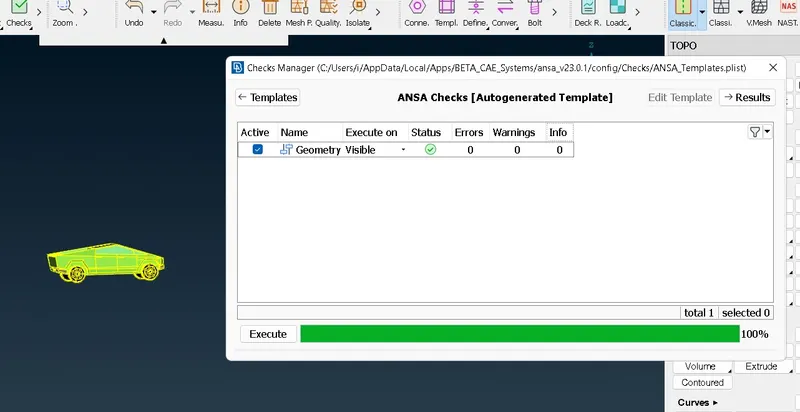
Geometry check
Checks<Geometry
No error found
Step 7
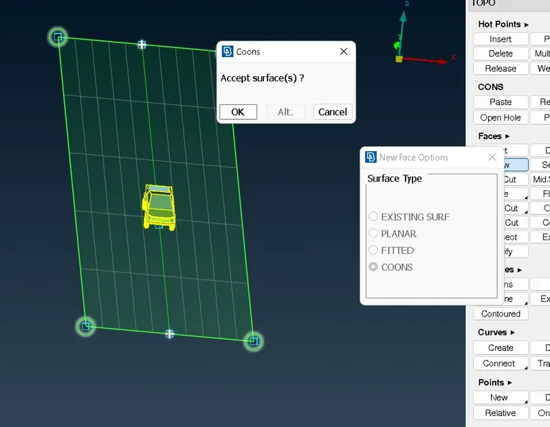
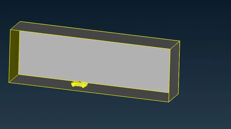
Wind tunnel
Wind tunnel distance
From front face = Truck distance from center to front + 4 X 5713 = 23742
From rear face = Car distance from center to rear + 6 X 5713 = 35859
Top face = Car height + 3 X 5713 = 18670
Bottom surface = -175 in negative z direction
Side surface = 5713
5713 = Truck length
Create curve and join points to create new surfaces
Classic mesh < Length < Perimeter < Select Object < Middle click < Enter value
Classic mesh < Length < Macros < Select Object < Middle click < Enter value
Mesh parameters < Select target length and element type < Click OK to confirm
Quality criteria < Select minimum and maximum length < Click OK to confirm
then
Classic mesh < Mesh Generation < Spot Mesh < Select object < Middle click to confirm
Top Surface target mesh length 100
Bottom surface target mesh length 20
For remaining four surfaces
Spacing < Biasing-Linear < Start factor-20 < End Factor-100 < Select four edges as shown in figure < middle click to confirm
Classic mesh < Mesh Generation < Spot Mesh < Select object < Middle click to confirm
Project file is larger than the given criteria so i am unable to upload it.
So here is the link of project in google drive
https://drive.google.com/drive/folders/1i0ZYhCLIe16MA_yPWZaSnNSprCWfPLAr?usp=drive_link