Project 1 : CFD Meshing for Tesla Cyber Truck
Aim:
For the given Tesla Cyber Truck model, check the geometrical errors on half portion. Create and assign PID’s, surface mesh the half model and do symmetry to the other side.
Target length for the different parts of a model are as follows
- Body: 3mm
- Rims and Tyres: 2mm
- Window: 2mm
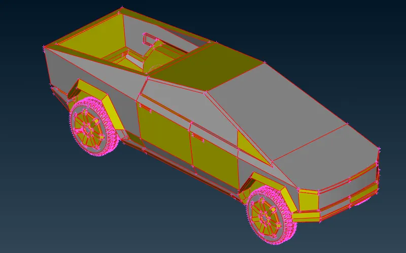
Procedure:
- Open ANSA, change to CFD mode then click on the “?” symbol another window is opened in which scroll down you will find “-performance_mode 3” copy and paste it near the “?” symbol click ok.
- Drag and drop the Turbocharger model in the ANSA window.
- Check for the units of the model and also check the resolution, Here the curves are captured very well.
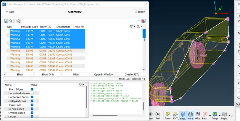
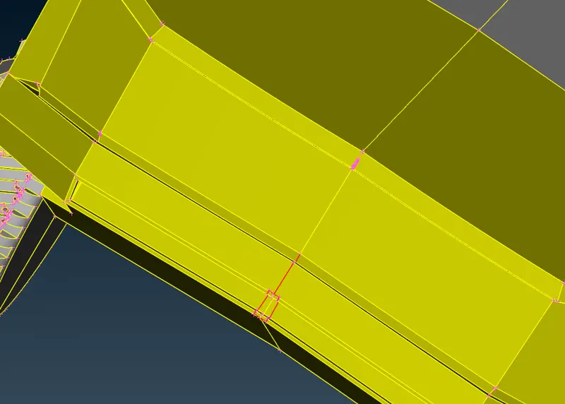
- At first, we could see lot of single cons, so we will use TOPO to resolve the errors. Most of the single cons are resolved
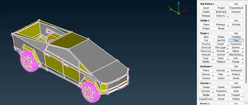
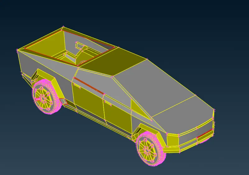
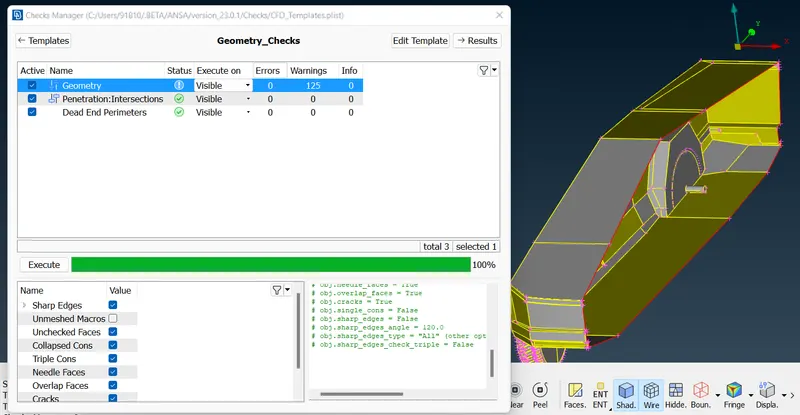
- Click on Tools >> Checks >> Geometry >> Execute. Now we could see the error which we need to clean up in topology in order to resolve the error.
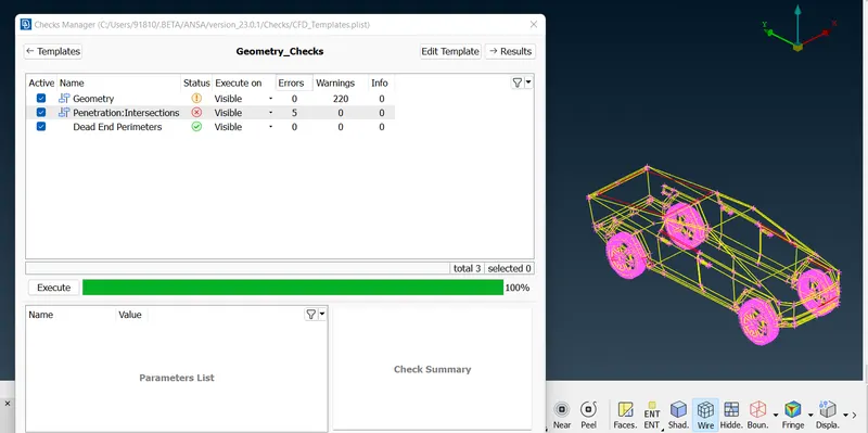
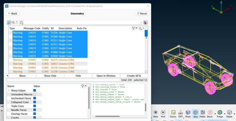
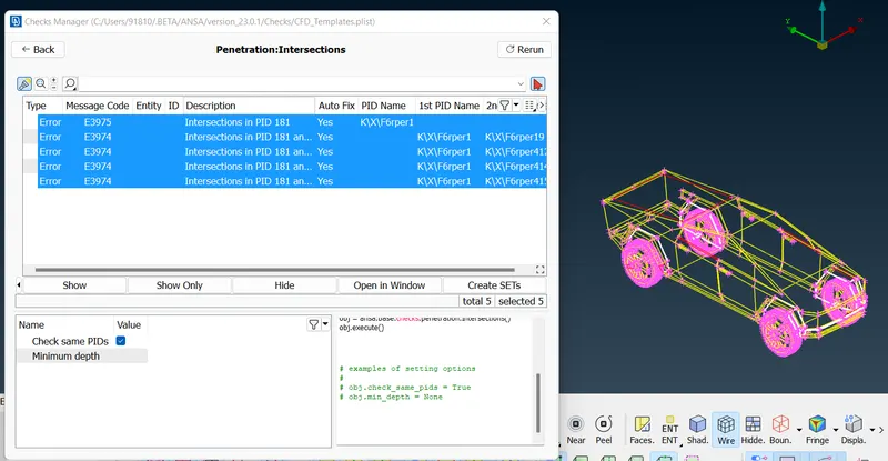
- It is necessary to resolve both the geometric and intersection errors.
- Since the model is symmetric in nature so delete one half of the model. Using plane cut option cut the model at the symmetry plane by selecting any three pointsand delete the other half of the model.
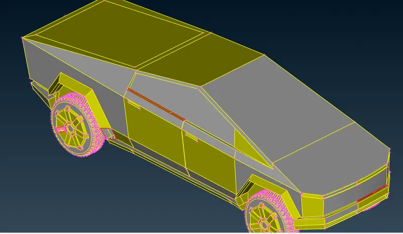
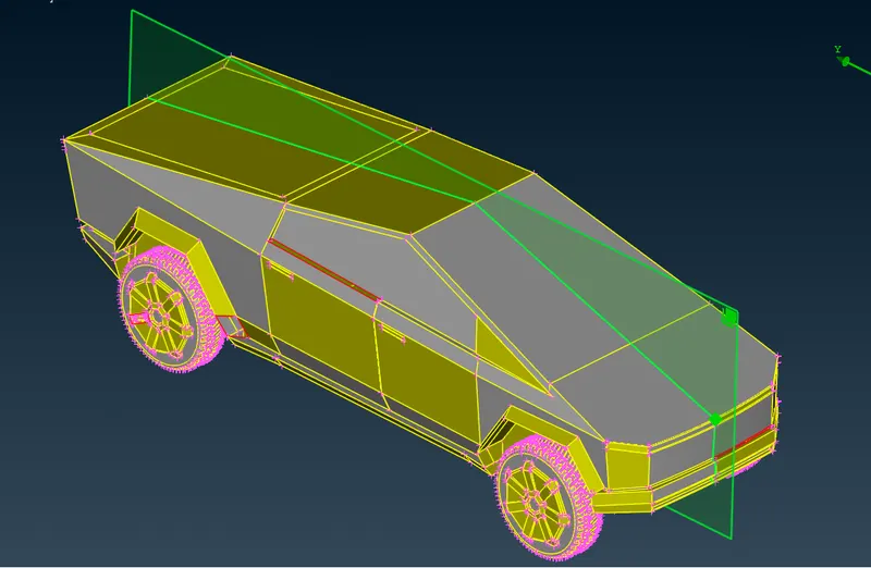
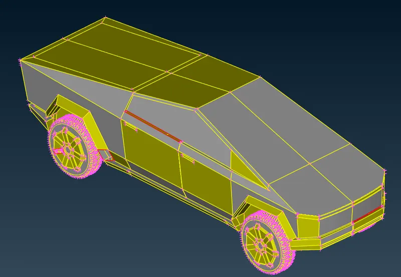
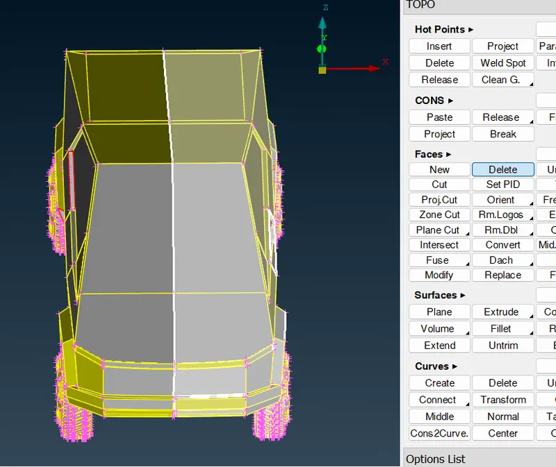
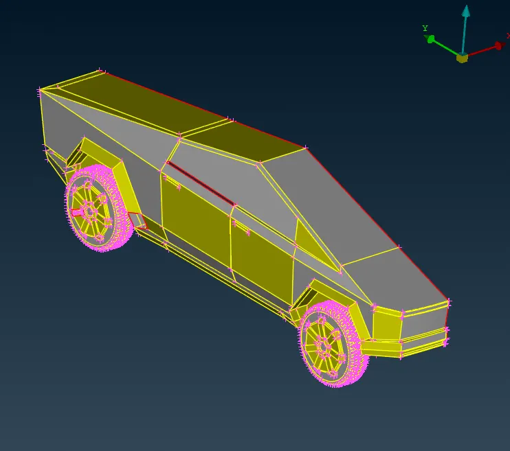
- In order to simulate the external flow over Truck we need to avoid multiple volume, so we need to create a single Truck volume model.
Missing Faces:
- At the back of the truck, it is open so we will create a new face at that section using TOPO >> Face >> New >> Cons >> Select the single cons >> OK.
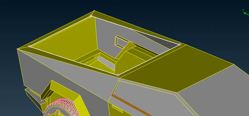
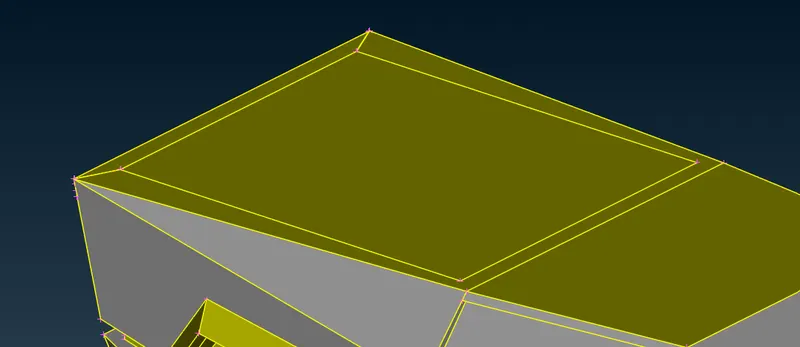
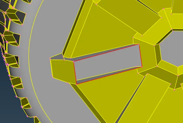
- Similarly resolve all missing faces in the geometry.
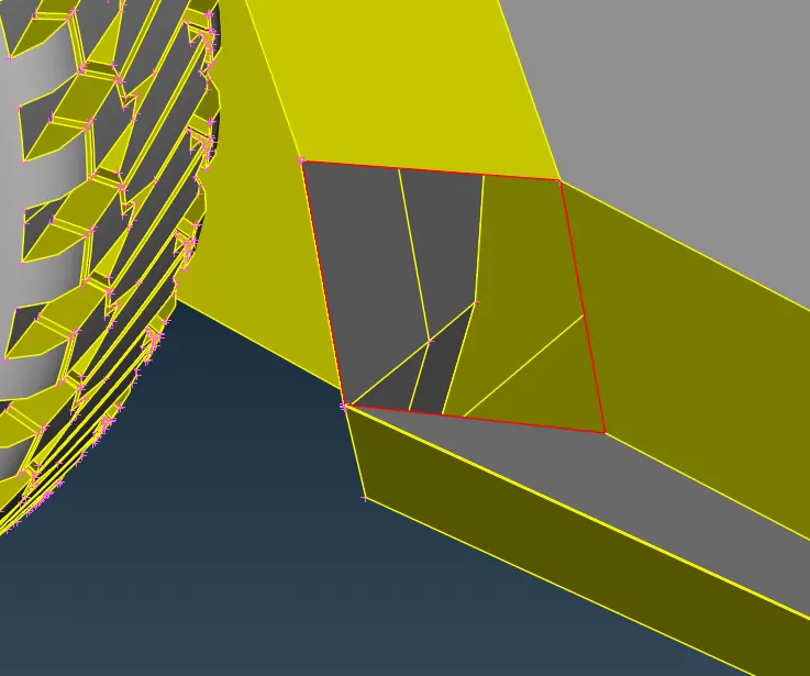
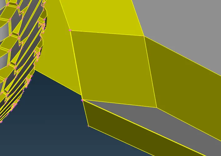
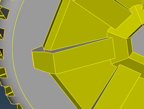
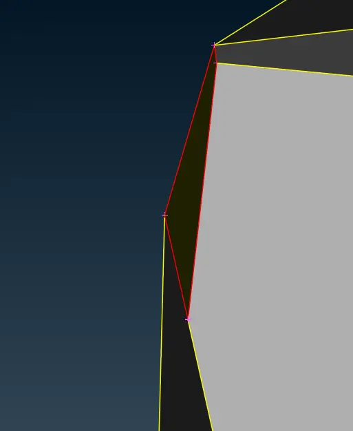
Side Window:
- There is a missing face but on close examining it is clear that the face is on a crooked surface so it cannot be easily created.
- So by using ANSA tools we try to repair that part and create new surface.
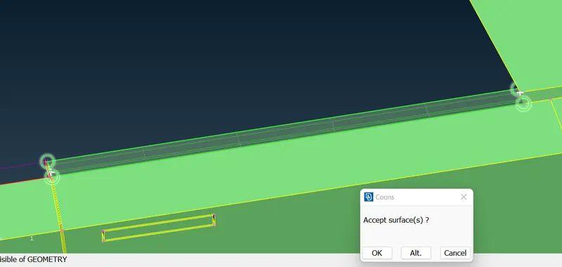
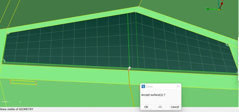
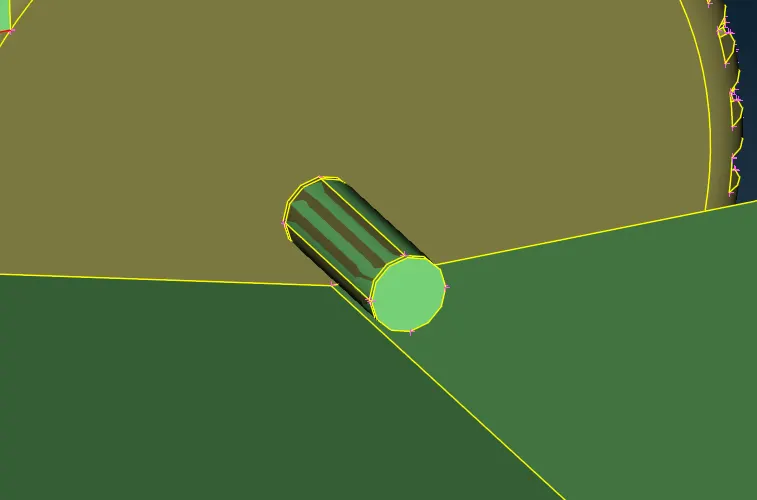
Wheel Glitch:
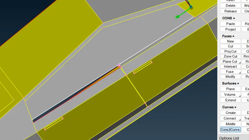
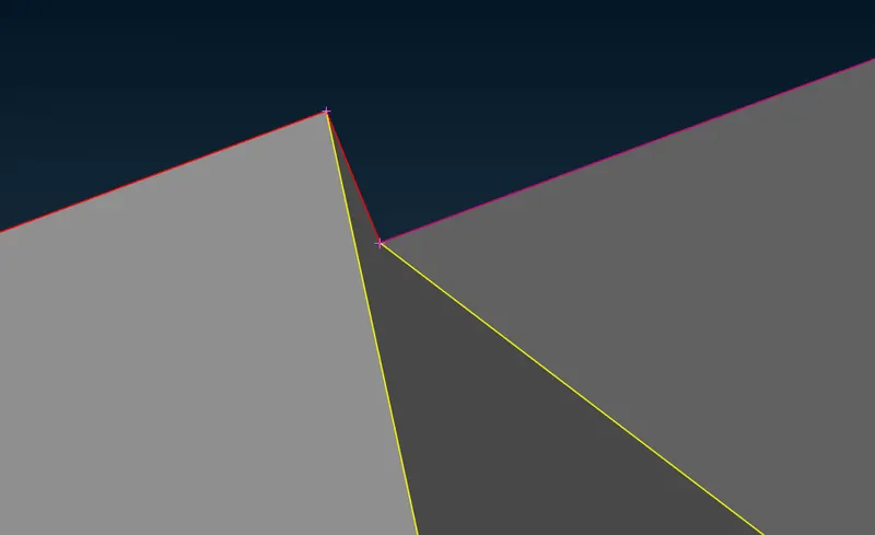
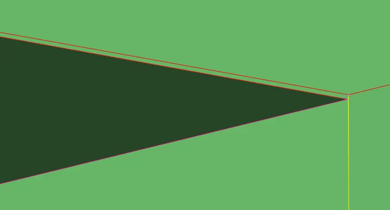
- While checking the intersection surfaces, we found that both wheel shaft has intersecting surfaces with truck body.
- So we delete the extra surface of the shaft.
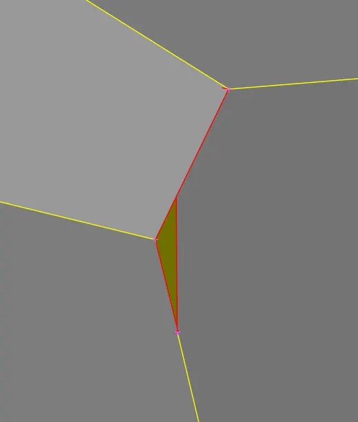
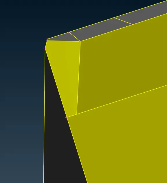
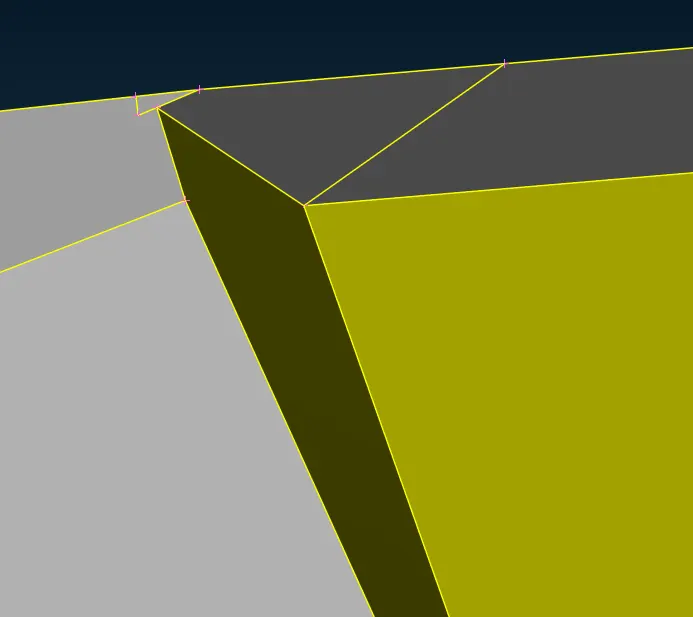
Front Bonnet Face Missing:
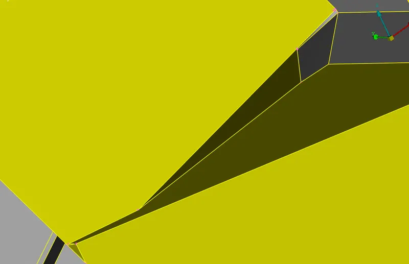
- As the planar surfaces join together there is a missing face at the bonnet section, this missing side has twisting surface so using single surface it cannot be created.
- Hence, we try to extend the surface and delete the unwanted surface using intersect tool.
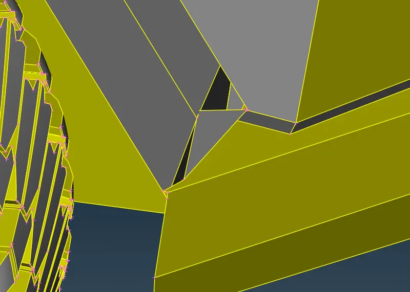
Near wheel intersection:
- The intersecting surface at the bottom near the front wheel has intersection, so deleted the surfaces and reconstructed the whole surface such that it will create less skew elements in the mesh generation phase.
PID Assigning:
- Check the geometry check again for the model, all the intersection errors are resolved only Single cons at the symmetry plane is visible which will be eliminated when we mirror the other half.
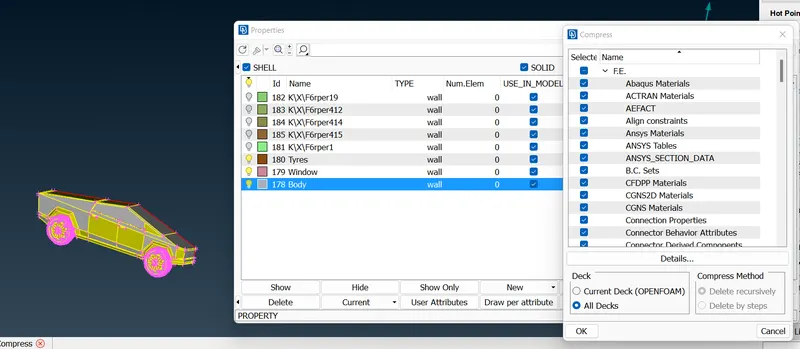
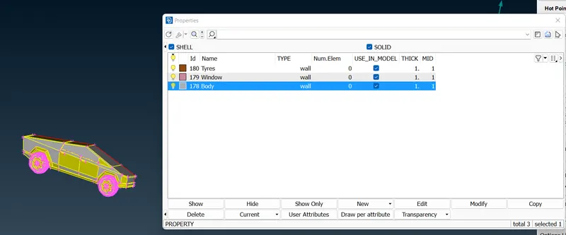
- Let’s start creating the PID’s for the model. Open the PID table New >> Shell Property >> Provide name >> Ok, similarly provide all the names.
- Right click the PID name >> Apply >> Select that part >> Middle click the mouse. Similarly follow for all components.
- In order to delete unwanted PID Click Compress >> Ok.
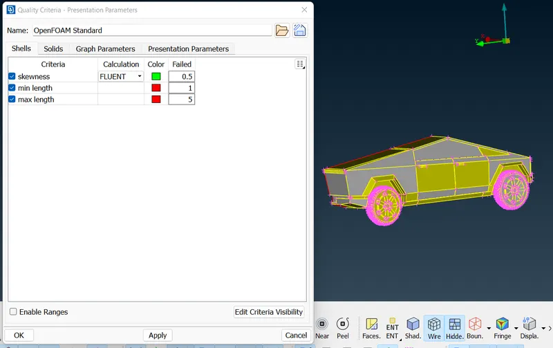
- In this model we will switch ON the quality criteria to check the Skewness, maximum & Minimum length.
- Open Quality Criteria >> un check the unwanted criteria in the shell & solid. Further Click Open Edit Criteria Visibility >> un check the unwanted criteria’s >> Ok.
- Let’s start component wise surface mesh. We will start with the minimum element size and then proceed to maximum.
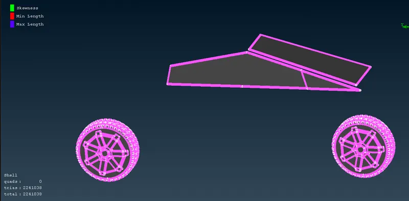
2mm Mesh: Rims, Tyres, Window
- From the PID table hide all the other component.
- Mesh >> Perimeter >> Spacing >> Auto CFD >> Perimeter >> Select the desired component >> Provide the Max. & Min. range for the element length >> Middle click mouse.
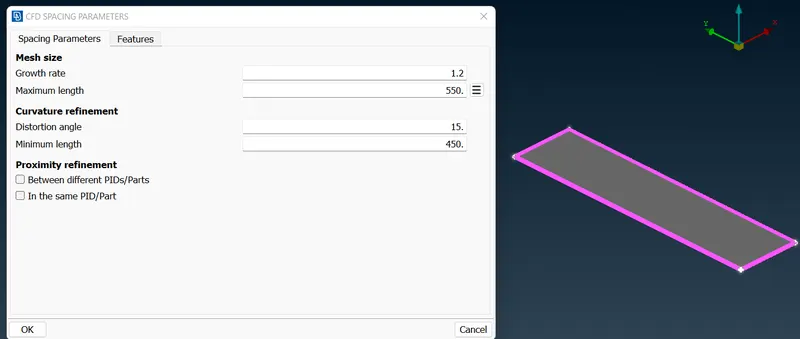
- Macros >> Select the desired component >> Provide the Max. & Min. range for the element length >> Middle click mouse >> OK. This Condition is provided to ANSA so that during mesh generation it is limited to the provided range.
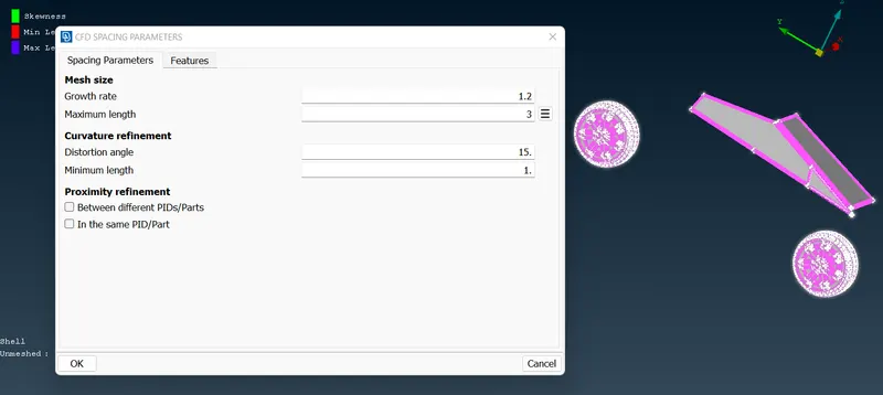
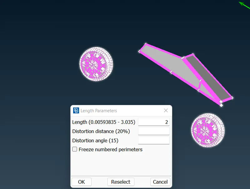
- Mesh >> Length >> Perimeter >> 2mm >> Ok >> Macros >> 2mm >> Ok.
- Mesh Generation >> Choose Tria element.
- Mesh Generation >> CFD >> Visible. Mesh is created.
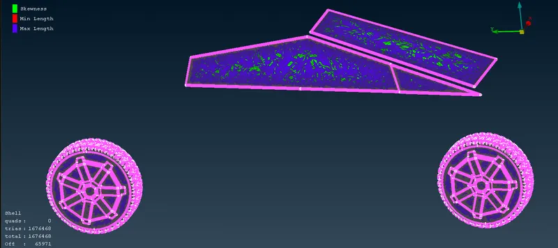
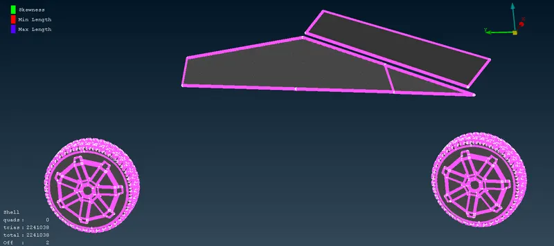
- Clear the off element using Reconstruct & Reshape method by right clicking the mouse on off element >> Improve. If still off element exist then move the node using move grid.
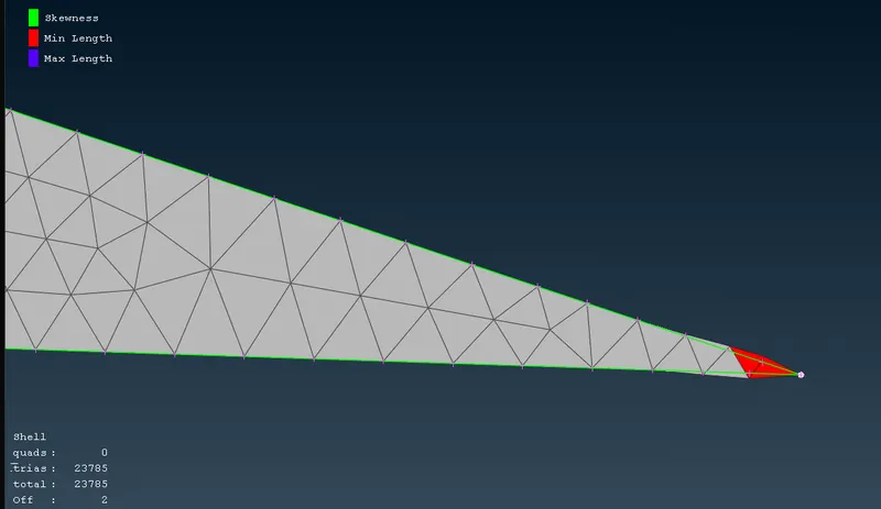
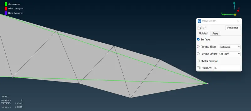
- Now, Freeze the entire component, without doing so mesh generation will not happen at any of the component due to varying mesh size at the intersection. Hence, we will freeze the mesh component at the end of mesh generation.
3mm Mesh: Body
- From the PID table hide all the other component.
- Mesh >> Perimeter >> Spacing >> Auto CFD >> Perimeter >> Select the desired component >> Provide the Max. & Min. range for the element length >> Middle click mouse.
- Macros >> Select the desired component >> Provide the Max. & Min. range for the element length >> Middle click mouse >> OK. This Condition is provided to ANSA so that during mesh generation it is limited to the provided range.
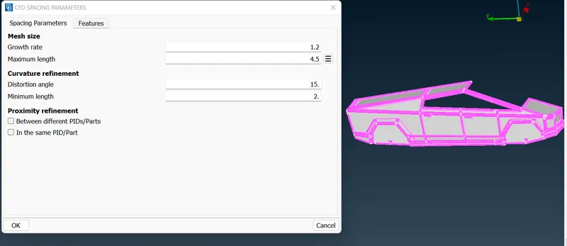
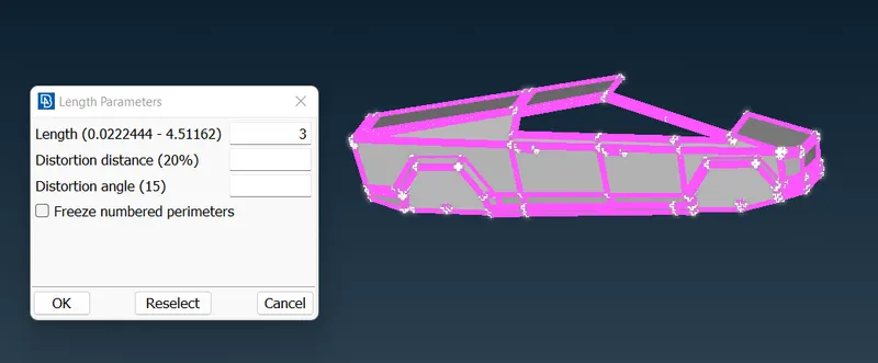
- Mesh >> Length >> Perimeter >> 3mm >> Ok >> Macros >> 3mm >> Ok.
- Mesh Generation >> Choose Tria element.
- Mesh Generation >> CFD >> Visible. Mesh is created.
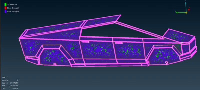
- Clear the off element using Reconstruct & Reshape method by right clicking the mouse on off element >> Improve. If still off element exist then move the node using move grid.
- Now, Freeze the entire component, without doing so mesh generation will not happen at any of the component due to varying mesh size at the intersection. Hence, we will freeze the mesh component at the end of mesh generation.
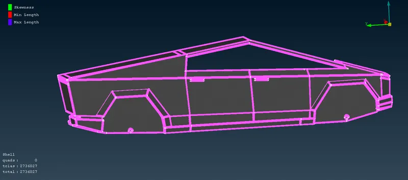
- Call all the components using AND command and unfreeze all component, Unfreeze >> Mouse right click select all component >> Middle click the mouse.
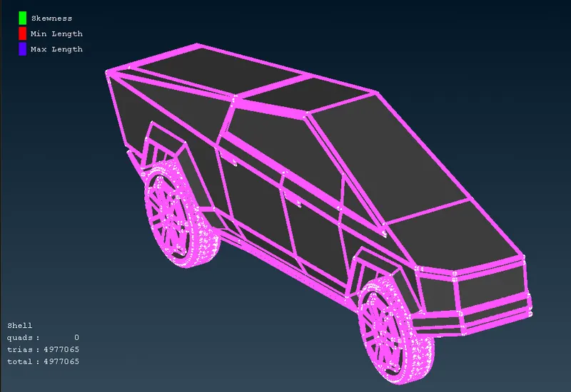
Symmetry Model:
- Once the surface mesh over the model is defined, Using Transform >> Copy >> Entities >> Select the whole model >> Middle Click Mouse >> Symmetry >> Three-point symmetry >> Select any three points where you need the symmetry plane >> Middle click mouse.
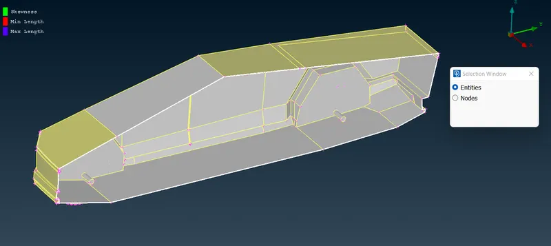
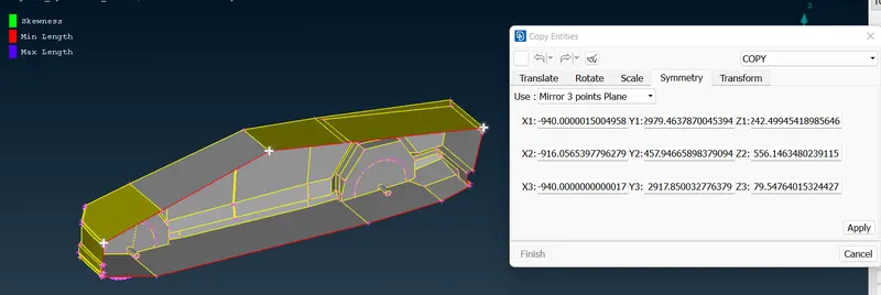
- once mirror the half section check at there intersection for single cons, intersecting faces and missing faces, resolve the errors using ANSA tools.
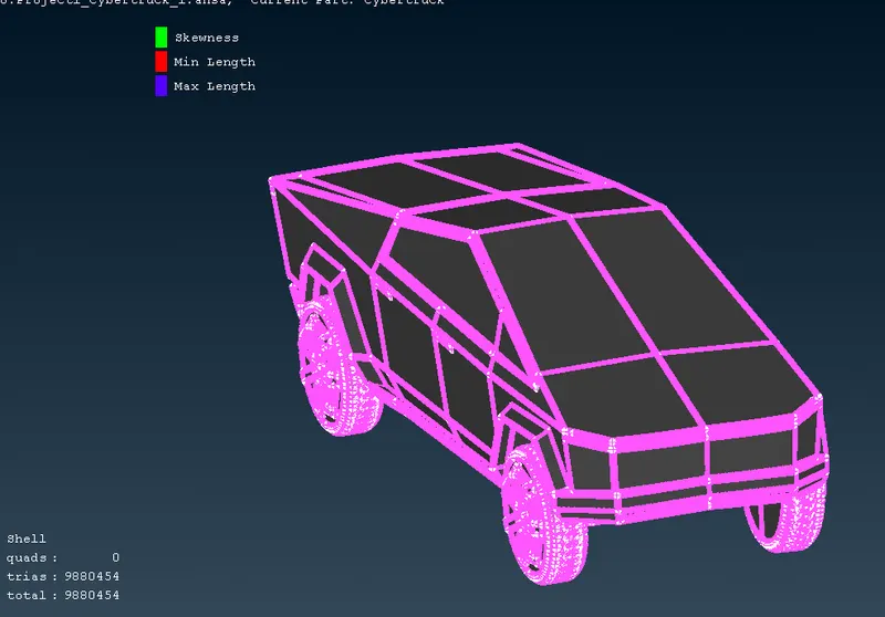
- Now, the whole model is created this method of deleting one half and resolving errors in other half, meshing the model and creating the other half using symmetry command is very much efficient & less time consuming.
Wind Tunnel Creation:
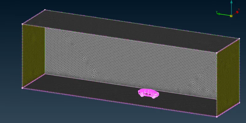
- We will start Creating Wind Tunnel around the Truck model.
- Measure the Truck model length (x), Inlet of the wind tunnel will at 4x from the front of Truck, Outlet will be 6x from the back of the Truck, Top of tunnel will be 3x from top of the Truck, both sides of the tunnel will be 1x from side of the Truck. Bottom of the tunnel has no empirical relation just create in such a way that it does not intersect the Truck model.
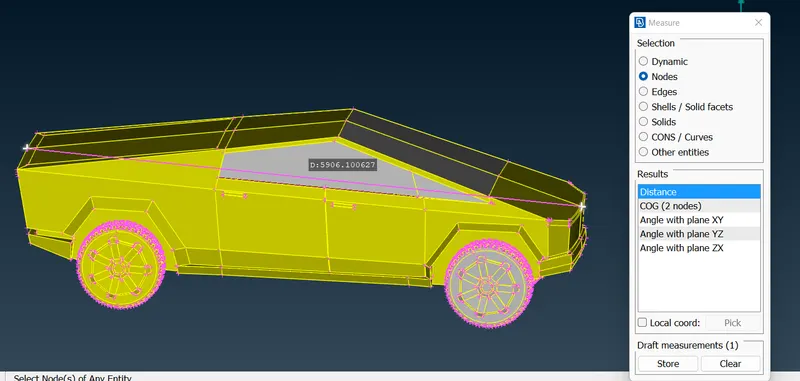
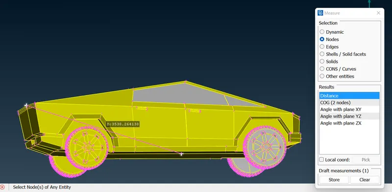
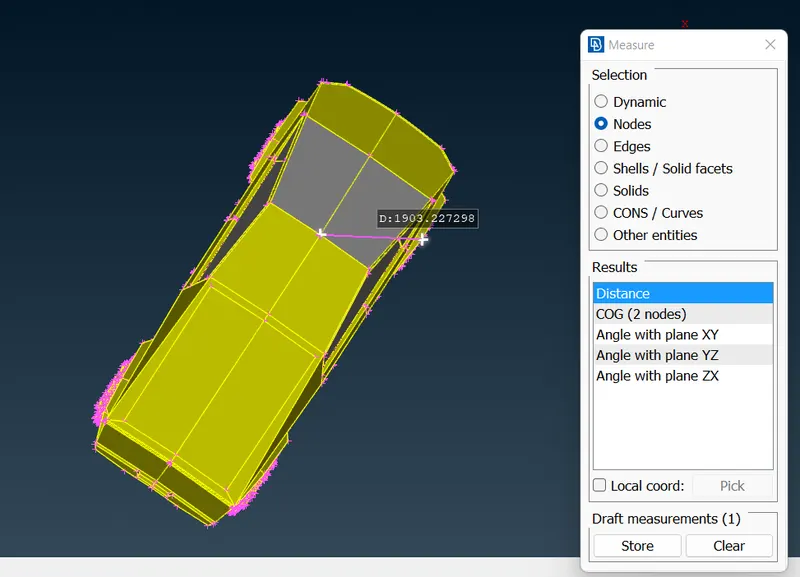
- Back to TOPO mode take a hot point at the bottom of the Truck and create a reference point below it, with this point as ref. start creating the front and back point, offset the points to sides.
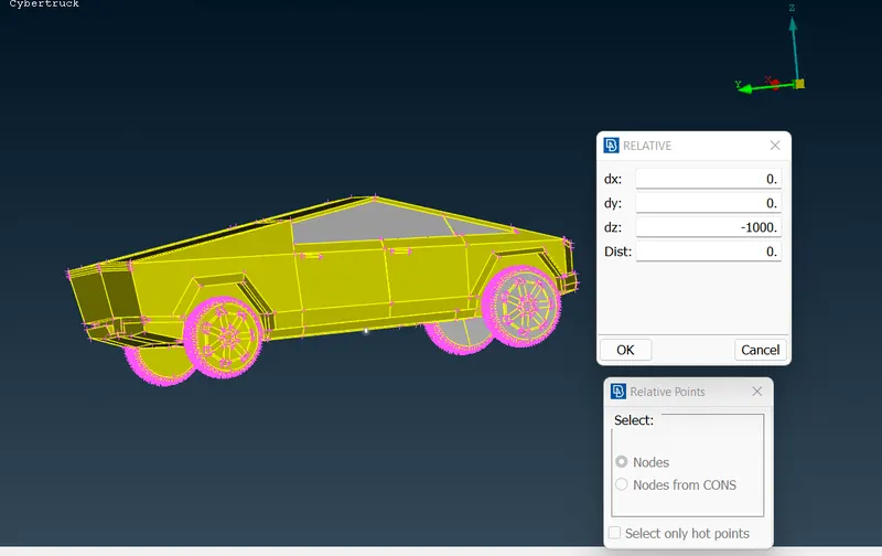
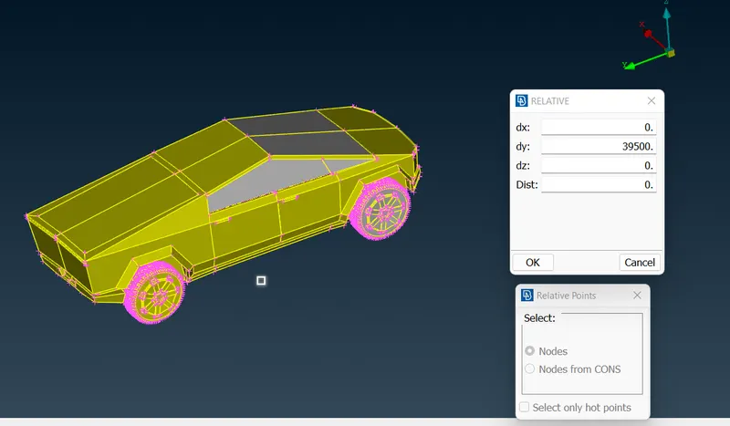
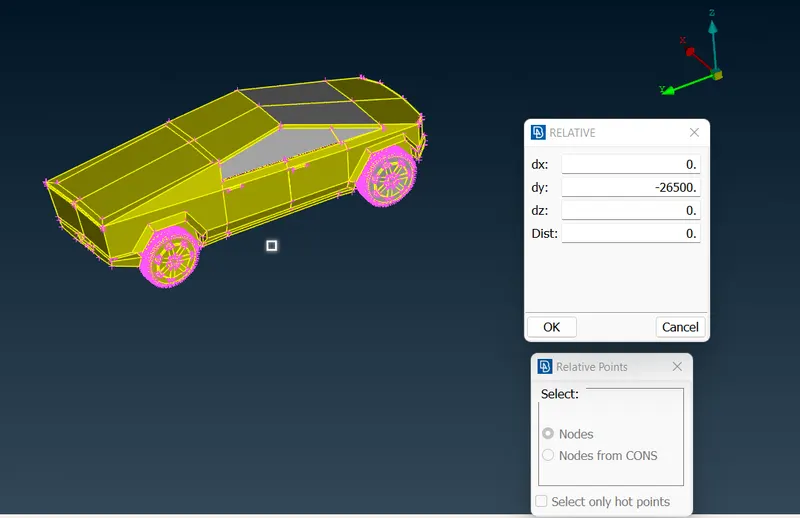
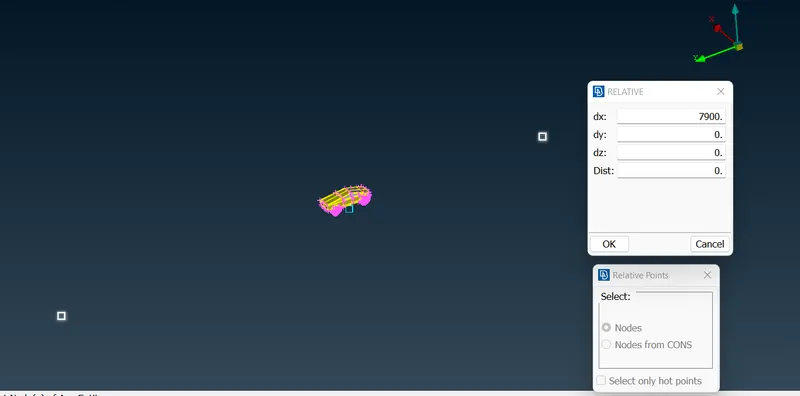
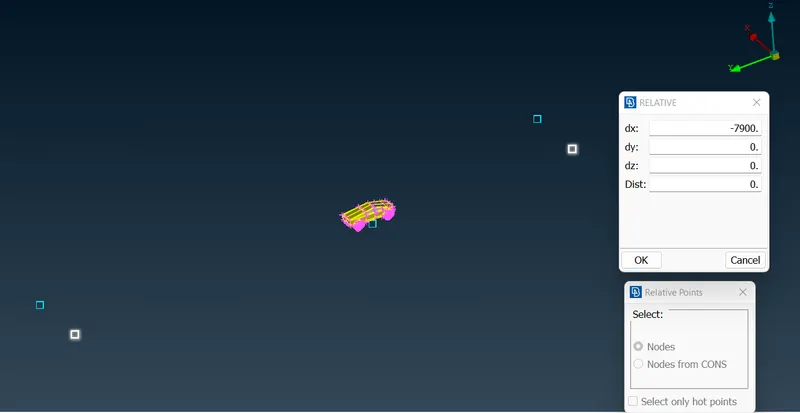
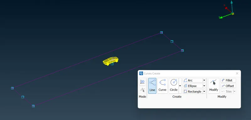
- Create curve joining the end points and then using face command create the bottom plane.
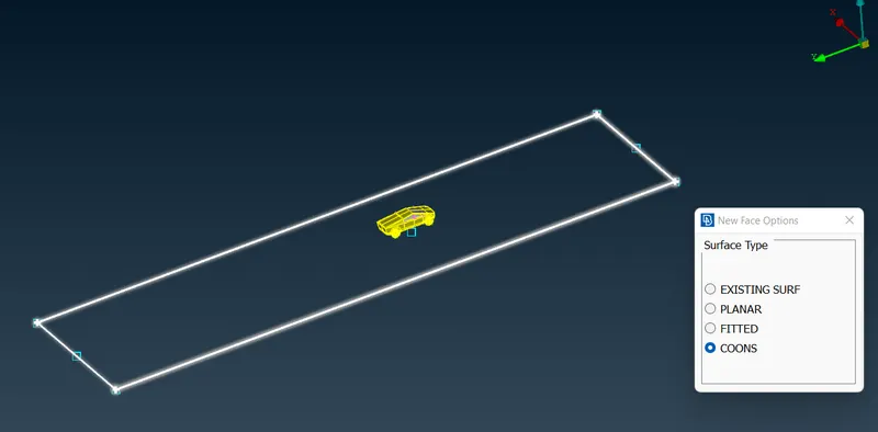
- Using Offset command, offset the bottom plane to the top plane using the top reference point and retain the original plane.
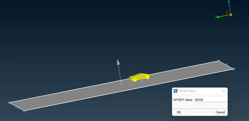
- Now using the face command >> Cons >> create the side faces. Assign PID for Top, Bottom & Side faces.
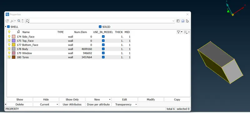
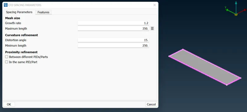
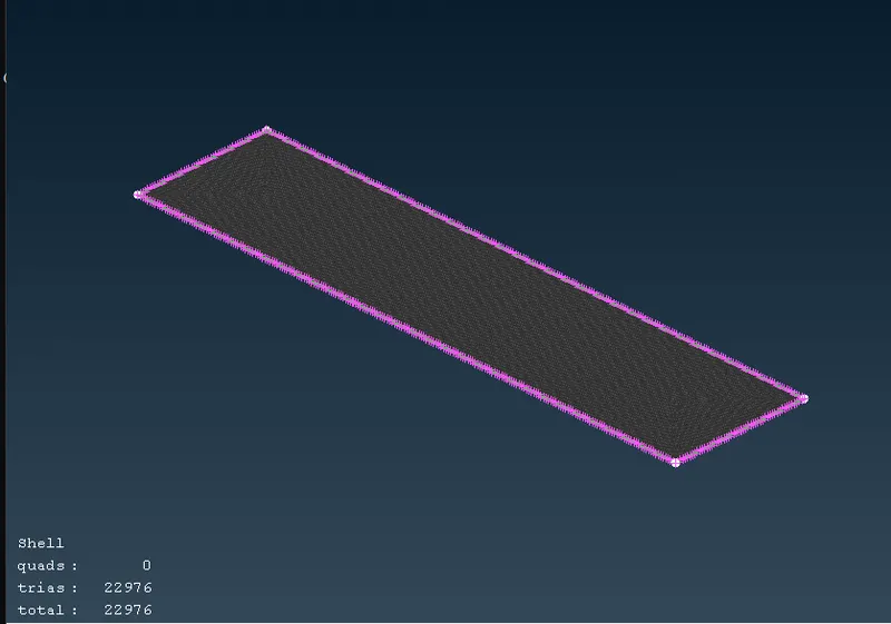
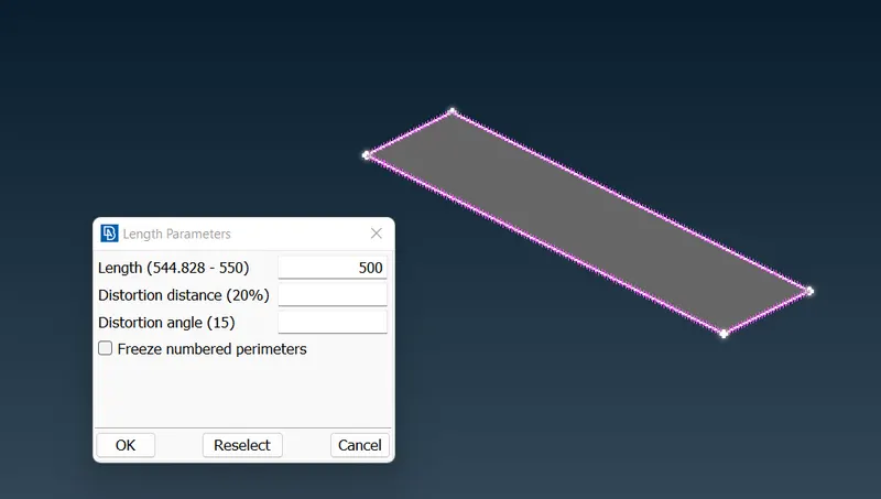
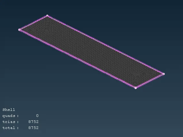
- Using PID hide all other components leaving only top plane and using Spacing provide the max. & min. Length for perimeter & Macros. Using Mesh >> CFD Visible command surface mesh the top face.
Bottom face:
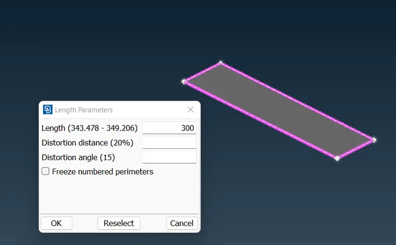
Top Face:
Side Face:
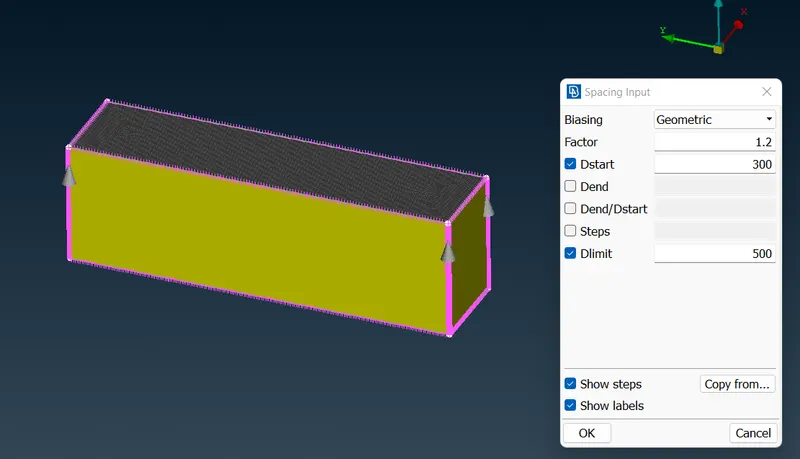
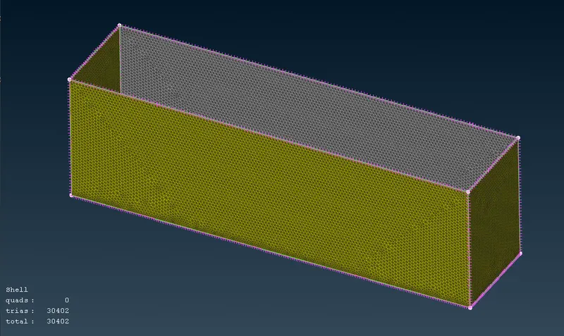
- Mesh the top surface by coarse mesh and bottom surface by fine mesh, so that growing mesh is obtained at the side faces.
- Spacing >> Auto Manual >> provide the D-start value as bottom plane mesh value & D-stop as Top plane mesh value >> Select the all-side Edges >> Middle Click Mouse.
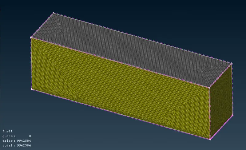
Volume Mesh:
- For this model volume mesh is not created due to limited resources, But have explained the procedure.
- Volume Mesh >> Define >> Delete the Un-Wanted volume, Keeping only the Tunnel volume. Since the analysis is to study the external flow over the Truck model.
- Type of volume mesh needs to be defined so select the Unstructured Mesh >> Tetra CFD for all the Volume.
- Right click in the mesh status >> Mesh >> Ok for all the Volume.
- In order to check the volume mesh, we use cut plane option. Cut Plane >> New >> Default XY (desired plane to view cut section) >> select the node as reference for the plane position >> Ok.
Result:
|
Sr. No. |
Element Size |
No. of Element |
Component |
|
1 |
2mm |
22,41,038 |
Rims, Tyres, Window |
|
2 |
3mm |
27,36,027 |
Body |
|
3 |
- |
98,80,454 |
Whole Truck model |
|
4 |
300mm |
22,976 |
Bottom Plane |
|
5 |
500mm |
8,752 |
Top Plane |
|
6 |
- |
30,402 |
Side plane |
- of elements in Surface mesh is 99,42,584 for whole geometric model.
Conclusion:
- Thus, given Geometrical model is resolved from all the errors and is prepared for volume mesh.
- Top & Bottom tunnel face element size is decided such that it puts less load to my system and still deliver a decent output result.
Mesh File:
https://drive.google.com/file/d/1brqAJ76q6WcZH1y5HfQnteUAn53W17ux/view?usp=share_link