Project 1 : CFD Meshing for Tesla Cyber Truck
Aim-
To Identifying & cleanup all the topological errors in the given Tesla Cyber Truck Car model.To create a surface mesh.To Create a wind tunnel around Tesla Cyber Truck Car .To create a volumetric mesh to perform an external flow CFD analysis simulation.
Procedure :
For solving we follow the below procedure ,
- Import the CAD model.
- Topo - To provide connection.
- Identifying & cleanup of the topological / geometry errors .
- Setting-up of relevant PIDs.
- Defining the element size or length,Setting the mesh parameters , selection of meshing type
- Generating surface mesh of the given model .
- Creating the wind tunnel for external flow analysis and surface mesh of wind tunnel.
1).Importing CAD the model :
To import the CAD model we follow below steps,
Go to file -> open -> browse the location of the CAD model -> select it click on open.
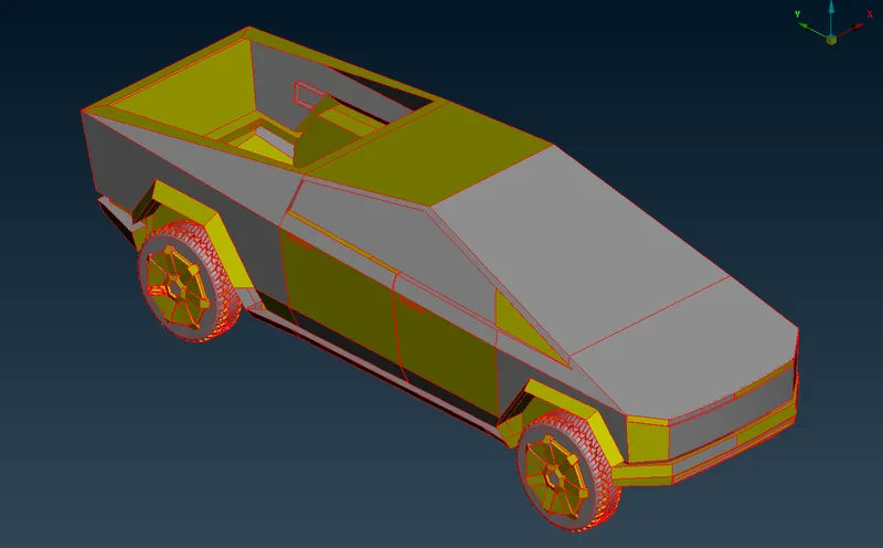
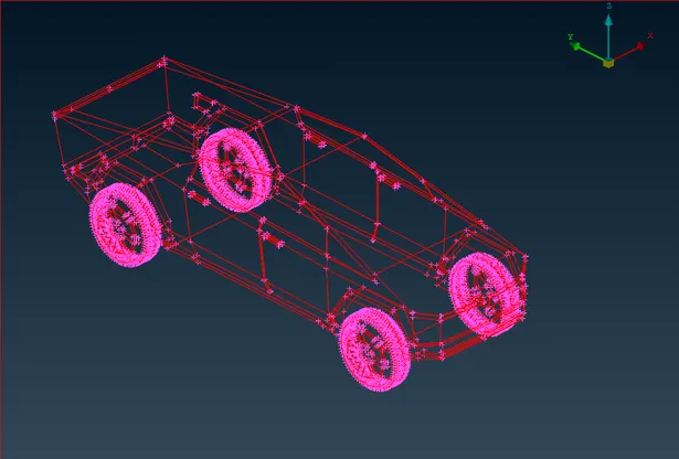
2) Topo - To provide connection.
Here in the above image we can seeonly single cons , let us do topo for whole model in the topo option all single cone get connect each other and make double cone.In the below image you can see the model after performing topo .
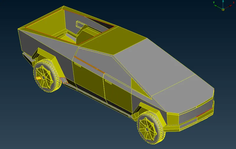
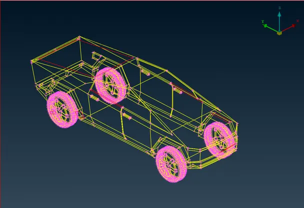
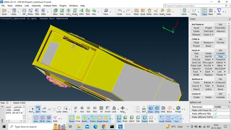
In the above image we can see the open face.here we can fill the open face by useing the fill hole option.
which is available in Topo module>cones>fill hile
In the below image you can see the model after performing fill hole .
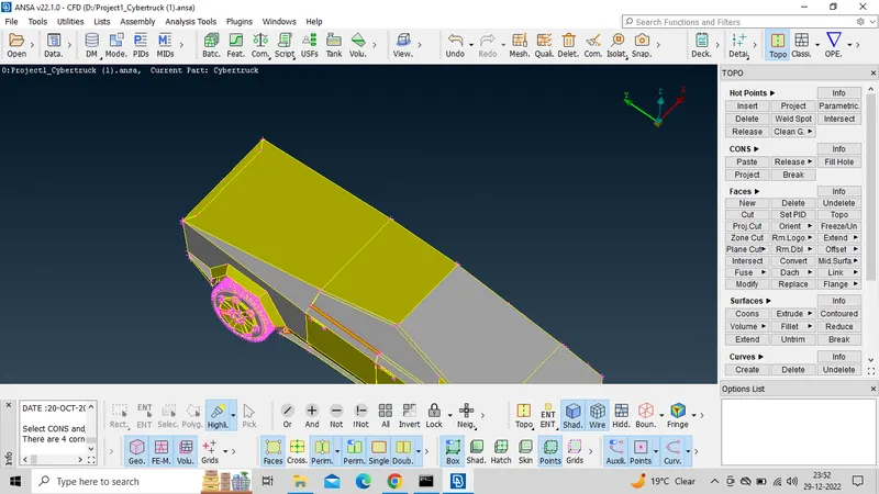
Use the plane cut on geometry so that it will be divided in two equal parts as shown below.
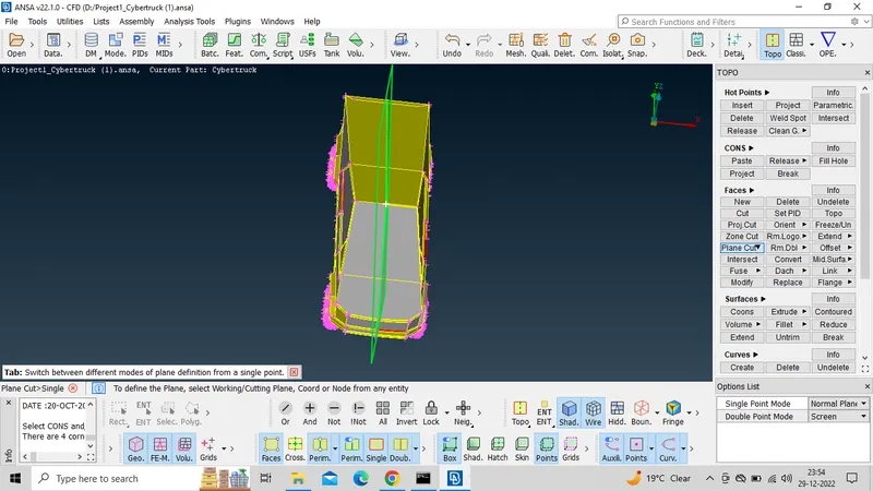
In the below image you can see the model after performing the plane cut it devide into two eqal parts .
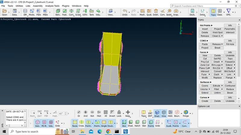
We find that the given geometry is axially symmetrical. Hence, we delete half part of the geometry and after complite all gemotry cleanup and meshing mirror that part to produce the other half.
Universal Delete > select half of the geometry > middle click
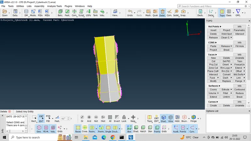
After complite the delete. we have to work on this half part.
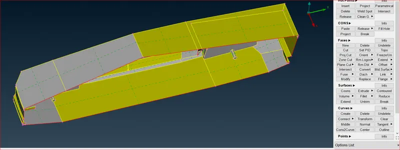
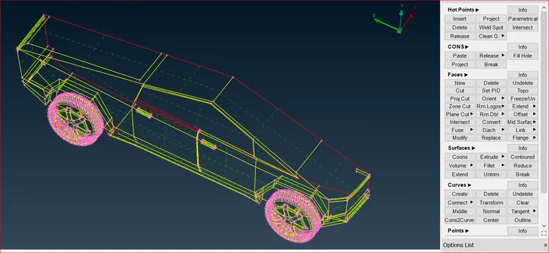 3) Identifying & cleanup of the topological / geometry errors .
Then go for gemotry cleanup.
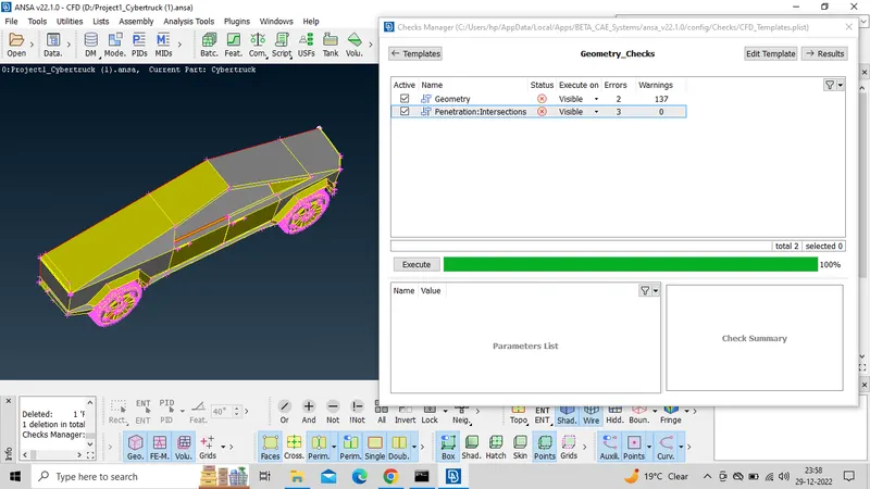
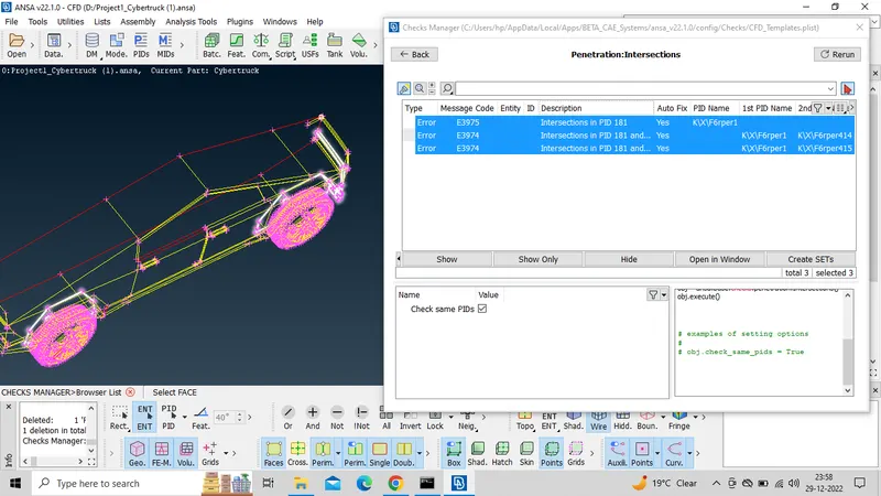
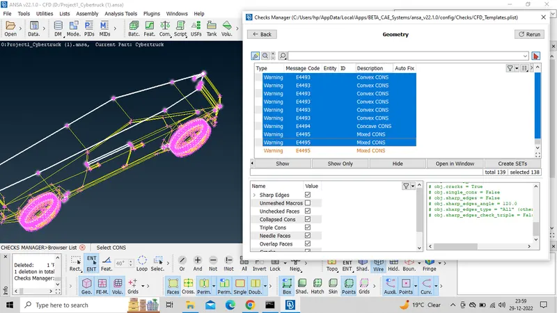
Here we can see all intersect error and gemotrical error. We have to isolate all the error one by one.
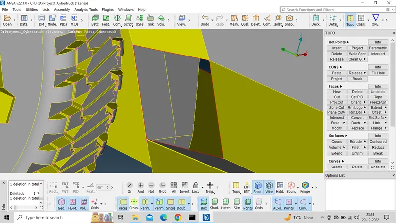
In the bellow image we can see directlly one face is missing.Here we can create the face by useing fill hole and new face (Cones).
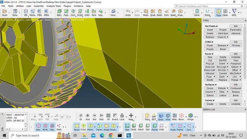
In the below image you can see the model after aplying the fill hole option.
Here also face is missing.here also we can create by same method.
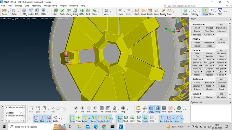
In the below image you can see the model after createing the face.
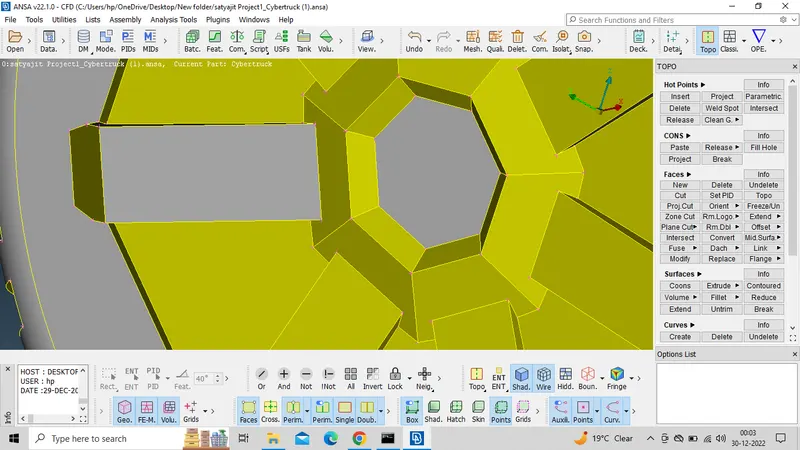
Here also we can create the face in the same way.
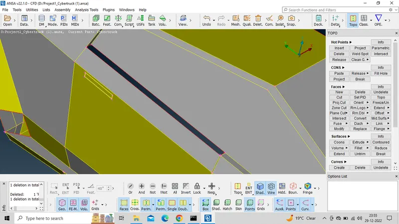
In the below image you can see the sharf edges. here we can make a cut and delete all the unwanted faces. Then create new face by useing the cons option which is available in Topo module>Faces>New>cons.
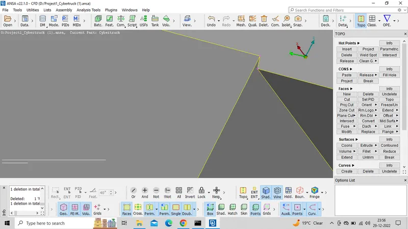
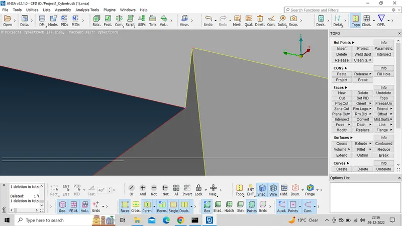
In the below image you can see the model after delete all the sharf edge and createing new faces.
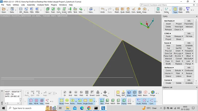
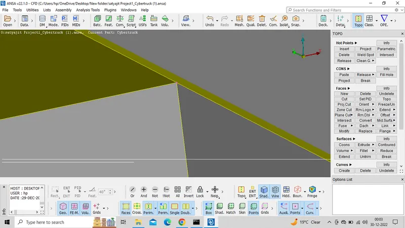
Here show the intersection error. We can avoid the error by deleteing all the unnecessary faces and crete new face according to our requirement.
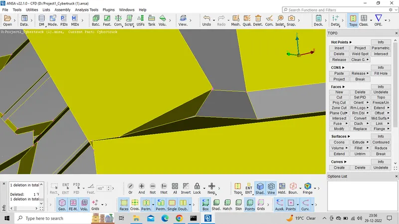
In the below image you can see after delete all the unnecessary face and creteing new faces.
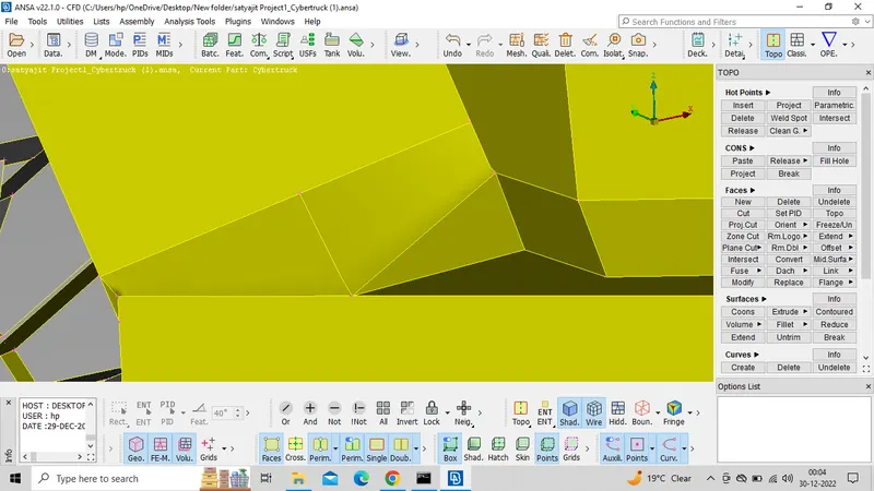
Here we can see the single cone.we should avoid the single cone by delete unwanted face and sharf edge.then create new face.
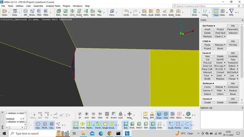
Here we can successful isolate the error . it see nice.
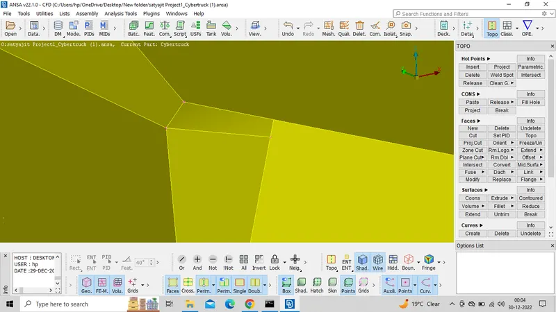
Here we can see unwanted face .we can directly delete the face.
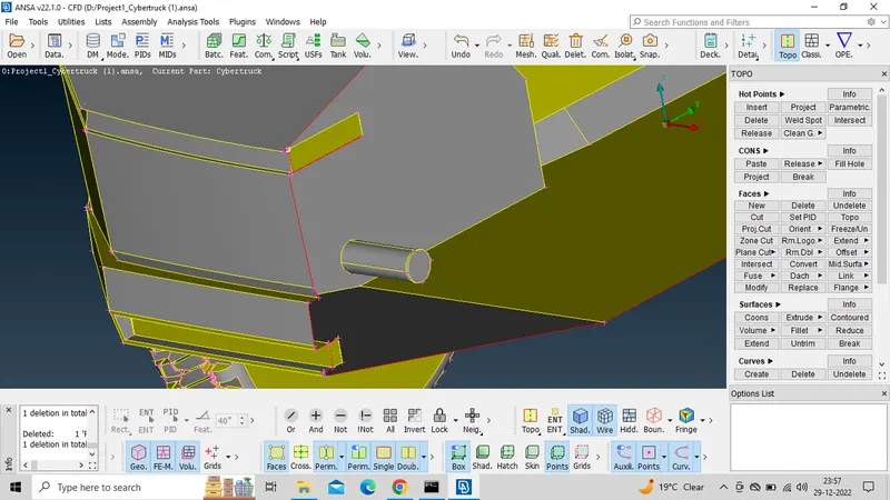
We can see the glitch part it is the intersection faces between the tries and axle of the wheel so we can directly delete the face which are overlapping with each other.
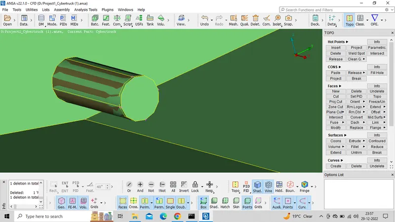
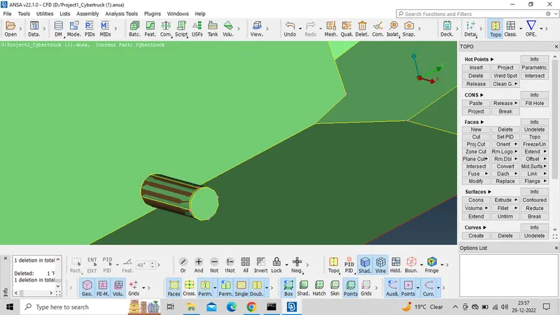
In the below image you can see the model after deleteing the overlap faces.
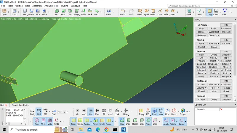
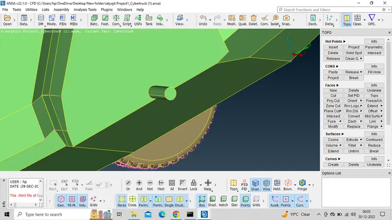
Here we can a hole due to axle .we can go directly fill hole option.
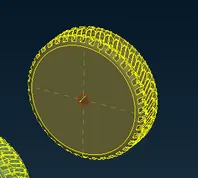
In the below image you can see the model after fill the hole.
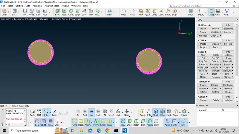
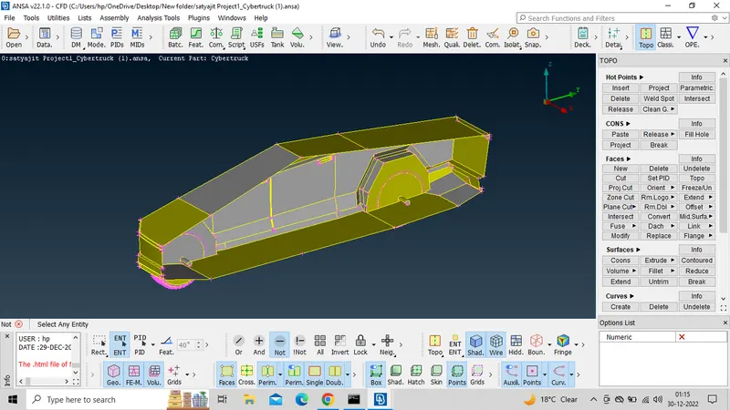
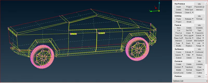
After clearing all the error . Once go for check the gemotry error.
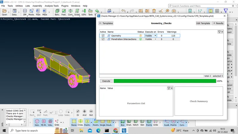
In the below image you can see the model after checking the gemotry error we are successful isolate all the error .
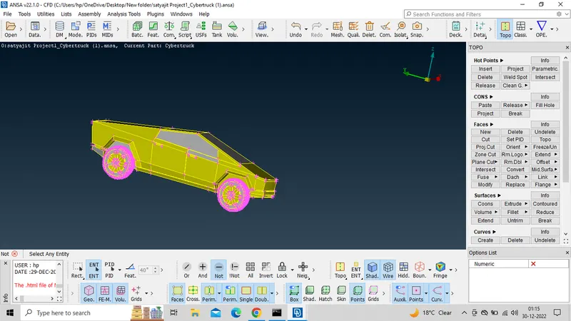
 4) Setting-up of relevant PIDs.
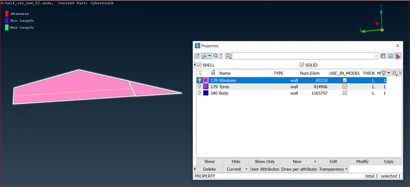
In this step we assign the PID for different parts and give a name and colour to differentiate between the components and ease up the working on the components individually.
Windows:
Tyres:
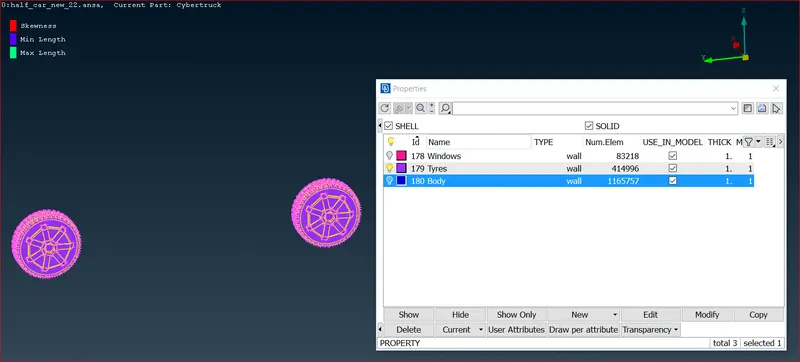
Body:
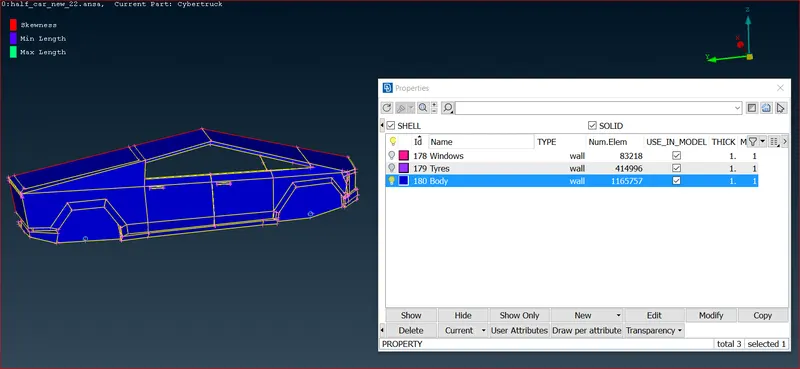 Then after assigning the PID , delete the empty orginal PID's which has no components assigned by using compress
5) Defining the element size or length,Setting the mesh parameters , selection of meshing type
Here we perform all the three tasks ,defining the element size or length and setting the mesh parameters, selection of meshing type and generating surface mesh of the CAD model and resolving the errors in the surface mesh by selecting each PID one by one and perform above tasks .
Before meshing we have to give quality criteria .Here we select openFoam solver deck,so that we get the quality criteria of that solver.
Lets apply uniform quality criteria to while car part
Goto quality parameter

Then new popup open.
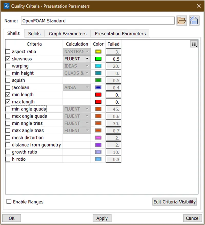
Now here enabled skewness,minimum length and maximum length.
Now remove all other quality checks parameter. For that goto edit criteria visibility a new popup opens and un check all other parameteres.
Now put values as
- Skewness = 0.5
- Min length = 0.2
- Max length = 6
Now click on apply then click on ok.we have successfully gives qulity criteria.
6) Generating surface mesh of the given model.
The given Target lengths for the different parts of a model
- Window/Tyres = 2 mm
- Body = 4 mm
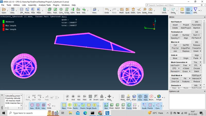
Let mesh window and tyres.
Goto pid manager and hide all other parts and enable only window and tyre.
- Let goto mesh parameter
- Here the target length=2 given. So give minimum length=1 an max length=3
- Now select the macros and select the faces
Lets go for body.
- Enable body and hide all other parts.
- Lets goto here the target length=4 so goto the mesh parameter and gives min length=3.5 and max length=5
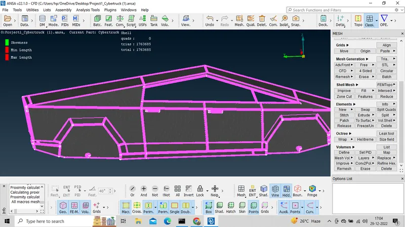
Note-1 There are few Off element we acn avoid this off element by improve option then reconstruct or reshape accordingly.
Note-2 After do meshing don't forget to freeze.
Afte cpmplite all the parts meshing go for all and unfreeze all parts.
Then go for symetry option.
Goto transform>copy>Now select the all faces>Hit the middle click, a new popup opens>Goto symmetry->mirror 3 points plane>Now select any 3 points>Click on ok
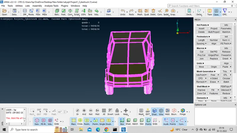
7) Creating the wind tunnel for external flow CFD analysis and surface mesh of wind tunnel.
Here the wind tunnel is closed volume entity like room which is used for simulate the external flow analysis of air over a car.
Let,Length of car = x
Front face at= 4x
Back face at = 6x
Top face at=3x
Bottom face = at convenient position that should not be touch the tyre of the car
Left,right faces at = x
- Now creates a points by taking reference of this point at a distance which mentioned above.
- now create the curves between these points
- Then create the bottom face
- the offset it at the required distance
- After createing top and bottom face assign to different PID
- Then meke the all side face and assign then a different PID
- Then go for meshing those face .
After doing those steps the wind turnnel look like this.
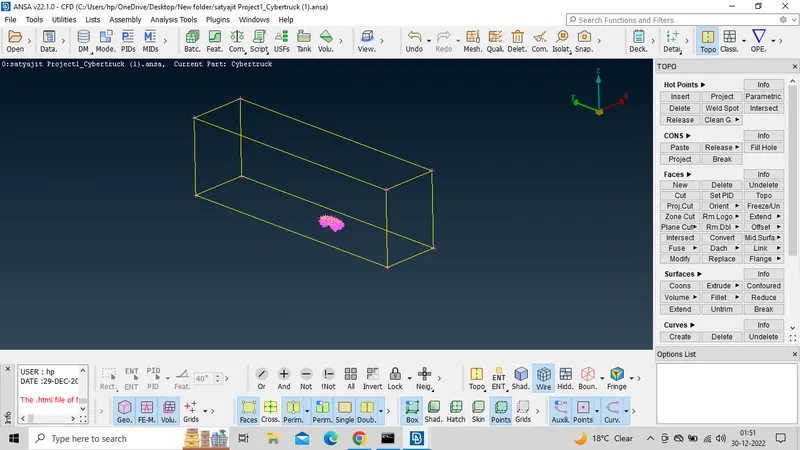
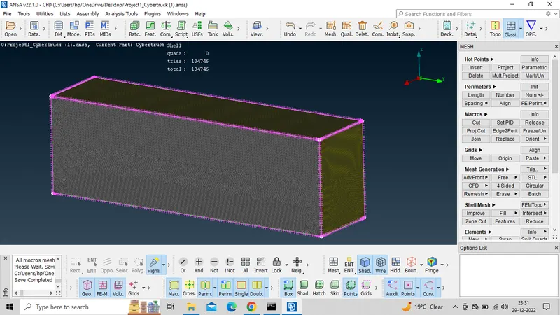
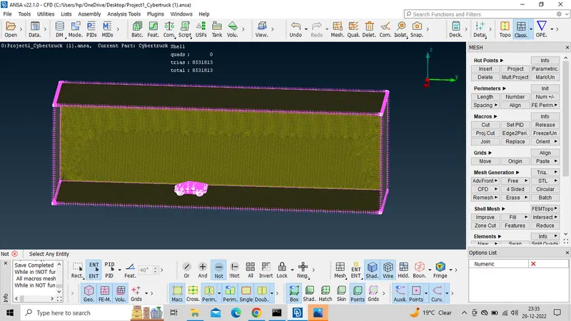
Following this phase, the final meshing should be done. However, due to system restrictions this work is unable to proceed.
Conclusion :
- The imported Tesla cyber truck is Topologically Cleaned & Corrected all the surface errors and intersect error.
- Surface mesh is generated with the required element size.
- Reconstructed the mesh as per the mesh quality required at Corners & at Intersection of edges.
- Worked with the errors occured in the Mesh.
- Created a wind tunnel For external flow analysis.
Surface meshing of the tesla car with wind tunnel google drive link
https://drive.google.com/file/d/15-cgXpwpaLvQULW-B7tEZMDDuU475717/view?usp=share_link