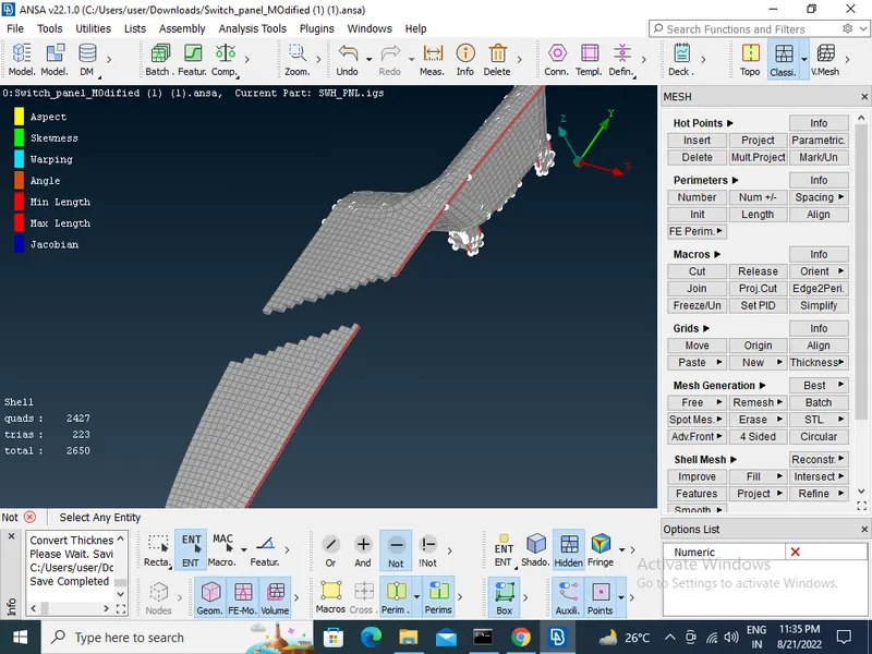
Tool Test 1
Aim:To perform the mid surface extracting and 2d shell meshing of the given component and obtain the 100% quality certeria and assign the proper thickness of the component.
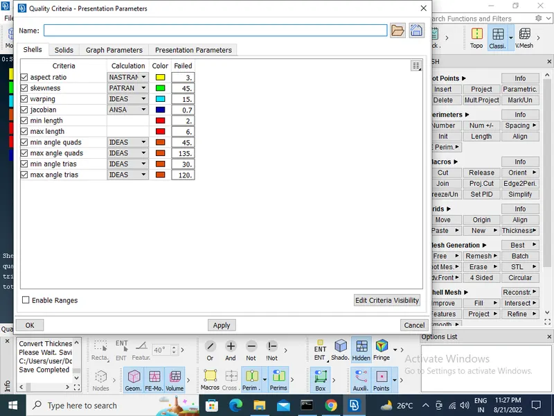
Following those Quality Criteria:
|
1 |
Target/Average length |
4 |
|
2 |
Minimum Length |
2 |
|
3 |
Maximum Length |
6 |
|
4 |
Aspect |
3 |
|
5 |
Warpage |
15 |
|
6 |
Skewness |
45 |
|
7 |
Jacobian |
0.7 |
|
8 |
Minimum Quad Angle |
45 |
|
9 |
Maximum Quad Angle |
135 |
|
10 |
Minimum Tria Angle |
30 |
|
11 |
Maximum Tria Angle |
120 |
|
10 |
Tria Percentage |
15 |
- Import the model File > Open > Choose the File and open.
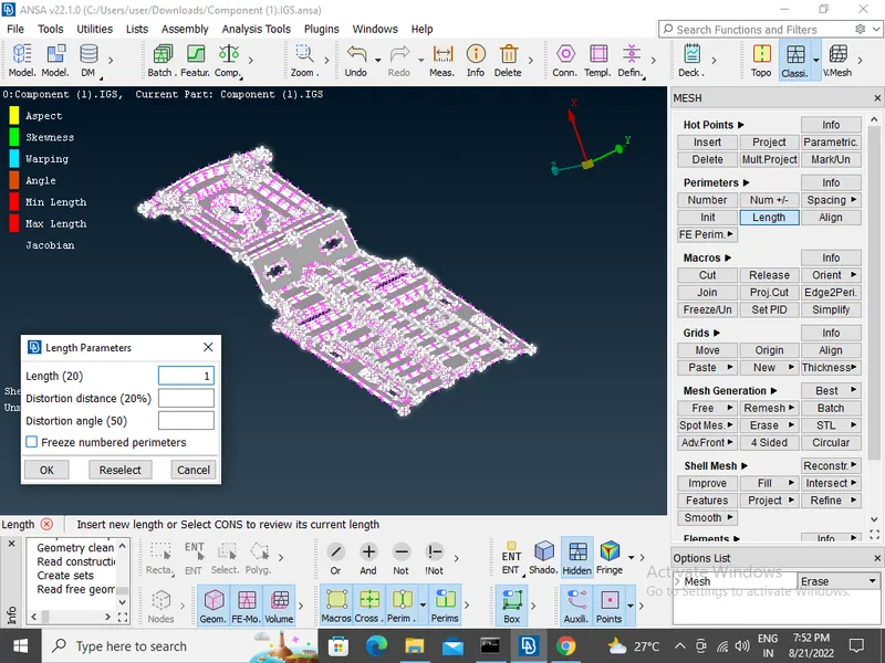
- Cons resolution by Length option in Mesh module.The Length value for doing the cons resolution is given as 1.Location of the option mesh module>perimeters>length.
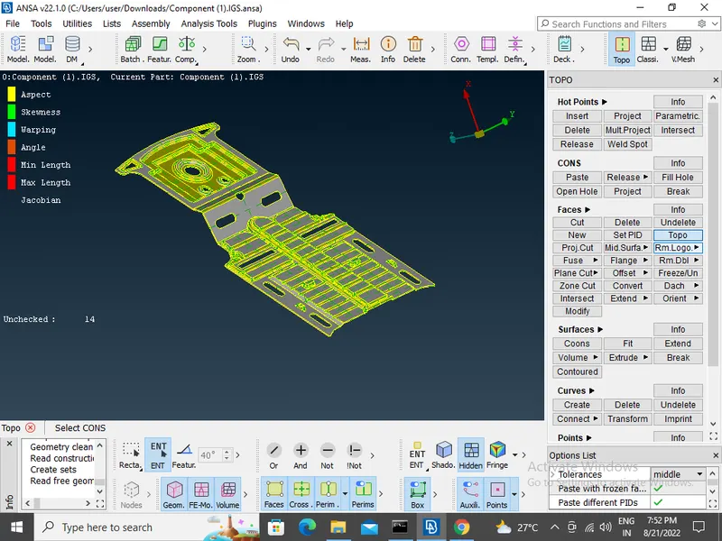
- Then to get the connectivity between the surfaces give the Topo option.locatiom of the option TOPO Module> Faces>Topo.
- Then Checking the geometrical errors.
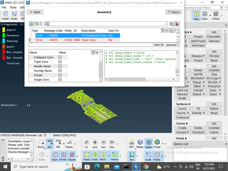
- Clearing the geometry errors.
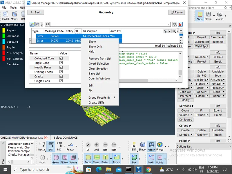
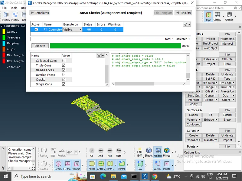
- Then measuring the thickness of the componentsis less than 6 mm or not. If is less than 6mm then go for mid surface extraction.
- Creating the midsurface for a sheet metal and plastics Component.
- If the components have the uniform thickness then using the Skin or Offset options to extract the midsurface.
- If the components have the nonuniform thickness then we will be using the casting or middel options to extract the midsurface.
- Then Providing the Target element length to the perimeters by using the length option in the mesh module.
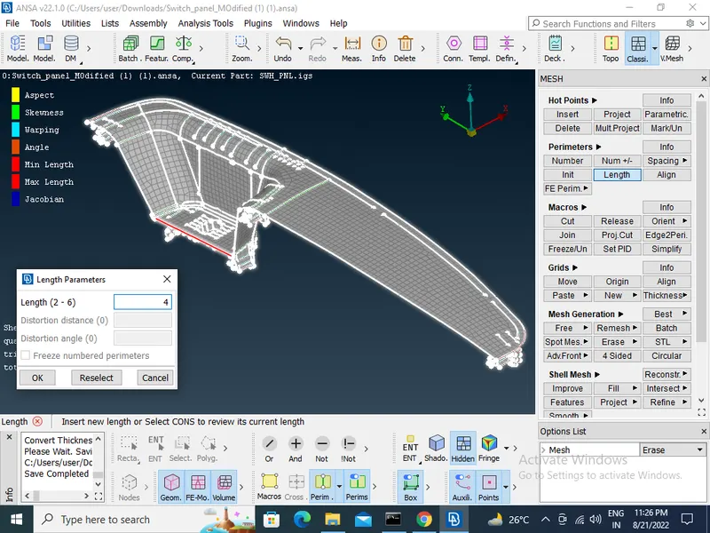
- Then Providing the Mesh Parameters and Quality criteria to the models.
- Generating the Mesh by useing the Best option in Mesh module>Mesh generation >best.
- Clear the elements which are failing for the quality criteria by Spliting the surface in the small square-like structures.
- Then Assign the proper orientation to the elements.
- ThenAssign the proper thickness for the newly created midsurface.
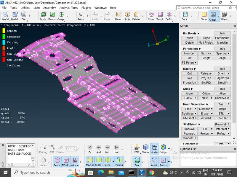
- IN THE SAME WAY ALL PERFORMANCE IS CARRIED OUT FOR THE SWITCH PANNEL.
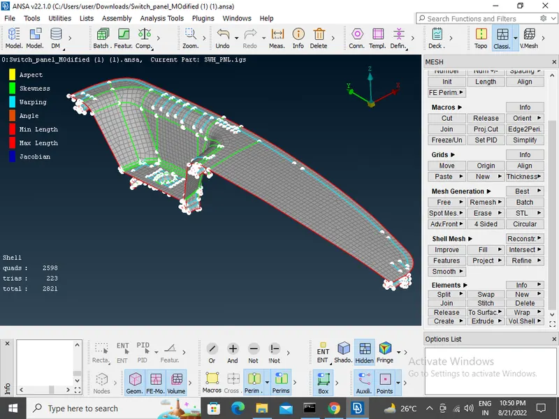
- After provideing the thickness.