Project 1 : CFD Meshing for Tesla Cyber Truck
Check for geometrical problems in the Tesla Cybertruck model that has been provided, solve them, and assign the proper PIDs. Perform meshing using the appropriate element quality and target length parameters.
Procedure:
We use the following process to solve.
Bring the CAD model in.
locating and fixing any topological or geometric flaws.
Verify your geometry.
setting up pertinent PIDs
defining the size or length of the n element.
CAD model surface mconvertedation, meshing type selection, and mesh parameter setting.
fixing the surface mesh's flaws.
constructing the wind tunnel and its surface mesh for exterior flow CFD investigation.
creating a mesh with volume.
Following the stages above, let's begin by resolving each one one at a time:
Importing the model from CAD
Follow the procedures below to import the CAD model.
Go to file > open > browse to the CAD model's location > select it and press open.
Geometry after applying TOPO tool
All single cons are converetd to double cons
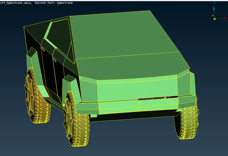
First step:
TOPO cleanup
Make a cut in geometry so that it can be split in half.
Always remove the portion of the geometry that required the least amount of labour to repair.
Repair bare surfaces
Remove surfaces that overlap and are extra.
Triple negatives to double negatives
diving geometry after doing intermediate cuts
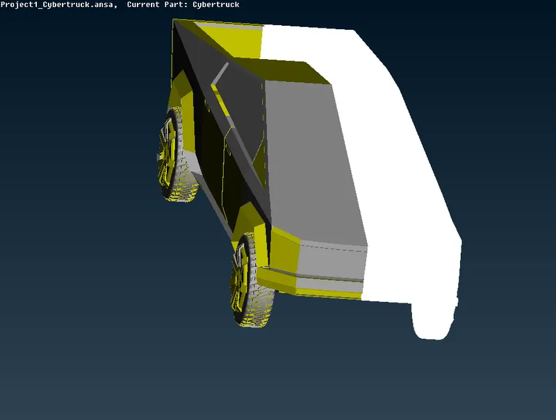
I have deleted the side on which there was more work required to be done in order to fix problems. Now work on half part, This is the best way to workon geometries which are symmetric.
Creating new surface to patch holes and clear single cons-
Patching First open surface
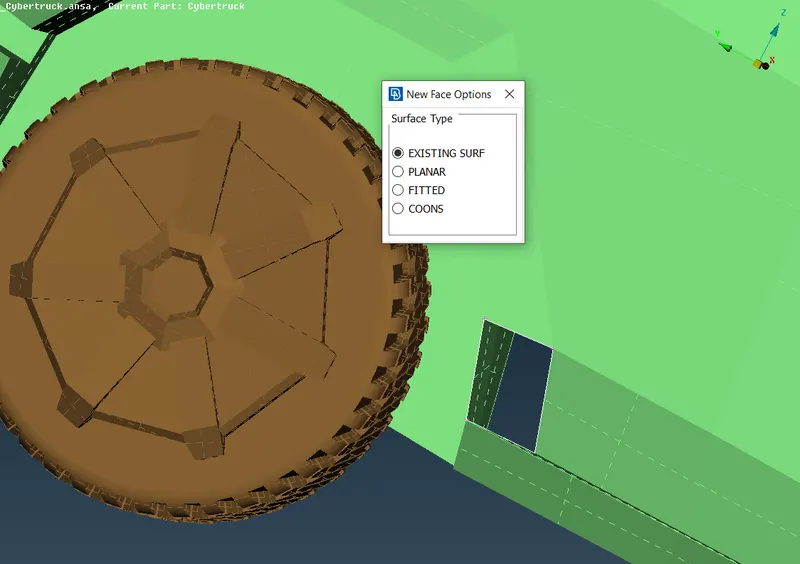
Patching second open surface
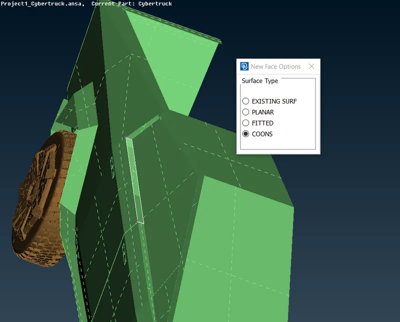
Patching third open surface
In below image image you can see brown color cylindrical surface penetrating with body, that brown part is part of wheel PID and delete that part then patch holes appeared on body and wheels seperately.
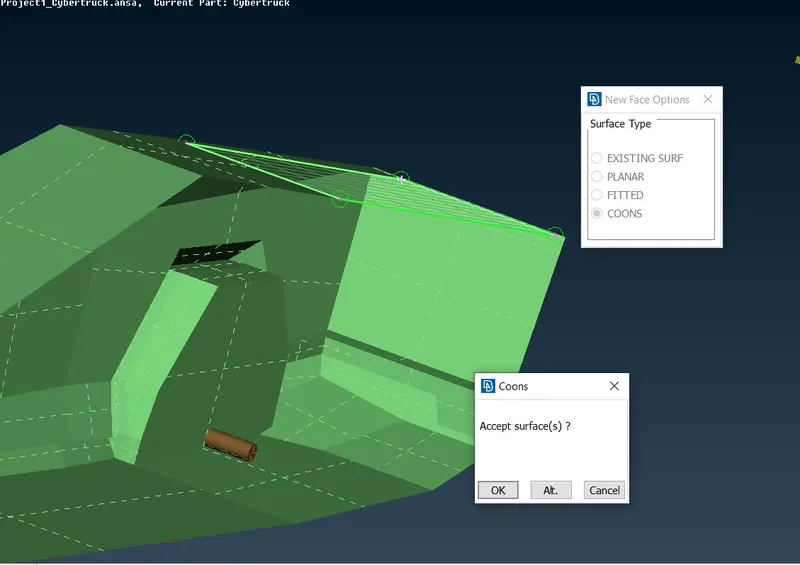
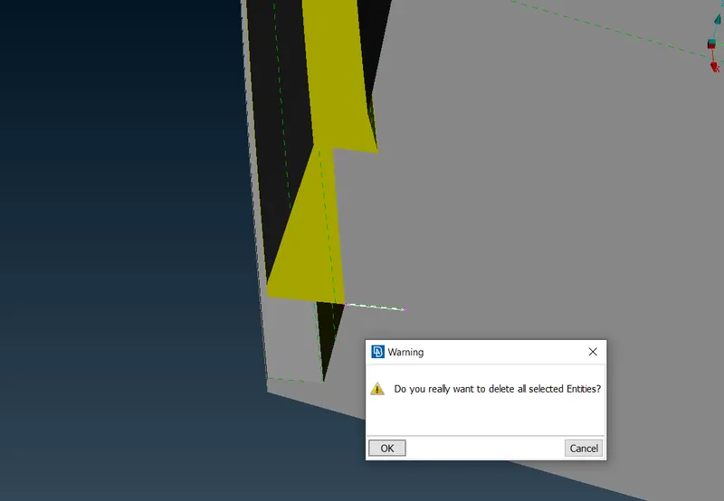
Deleting wheel PID part and then patching hole which appears in body and wheels seperately
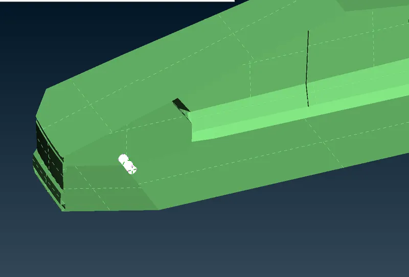
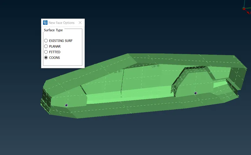
Sharp Edges
You will often face very small sharp edges on geometry which can be seen only when we zoom in or when we do geometry check.
- we can directly delete those sharp edges
- If we cannot directly delete them, create cuts and seperate those edges from large PIDs and tehn delete them
- Delete hot points which are not required
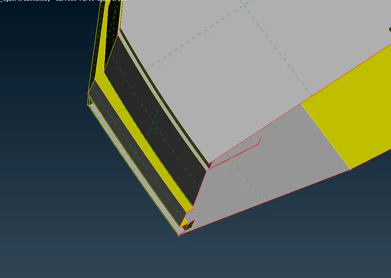
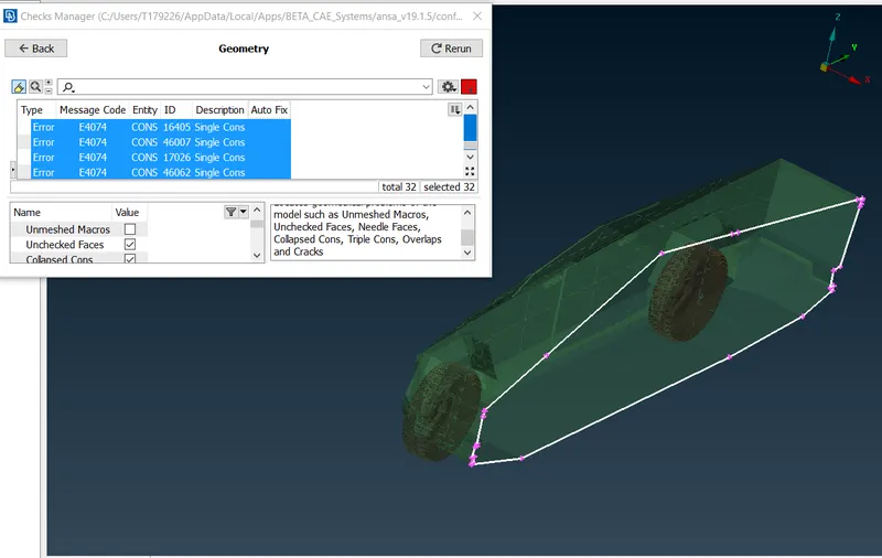
Geometry check after Topo cleanup
By doing we check there are no unnescessary single cons present and we are good to go for symmetry
CREATING SYMMETRY
- Go to transform tool and choose copy, a dialogue boz will appear , choose entity and drag your mouse doing right click to select whole geometry and do right click.
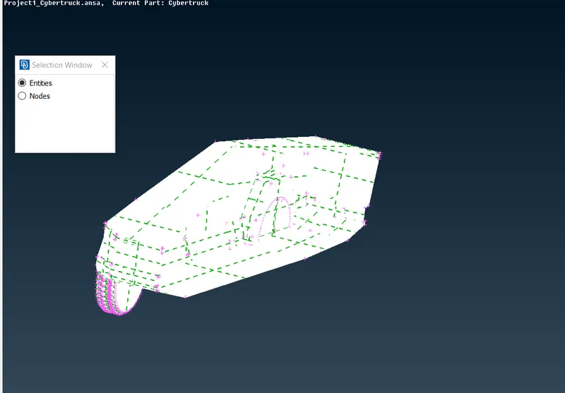
- In the new dialogue box which appears choose symmetry and three points plane
- Choose any three points to automatically fill required coordinates.
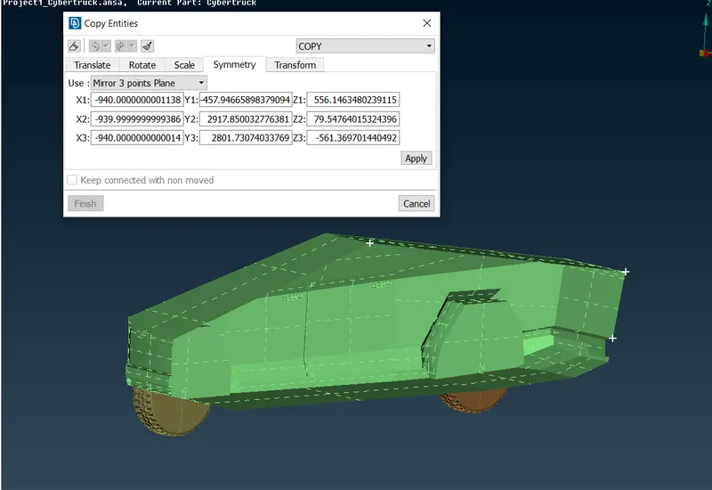
- click on apply and tehn click ok in the new dialogue box which appears . Don't make any changes.
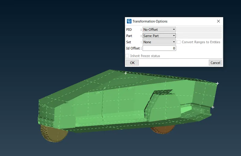
SYMMETRY DONE
Check for single cons as this common error after doing symmetry and solve them by using patch tool or by creating new surface.
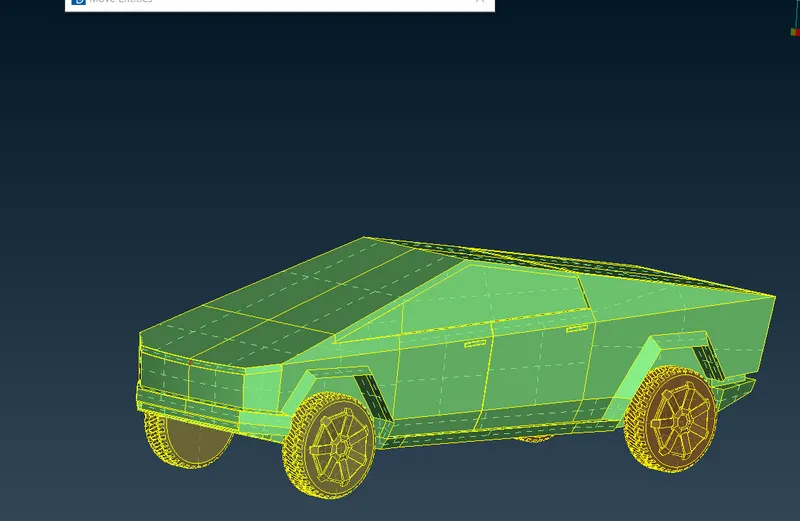
Geometry Check done
Geometry is ready to go for meshing
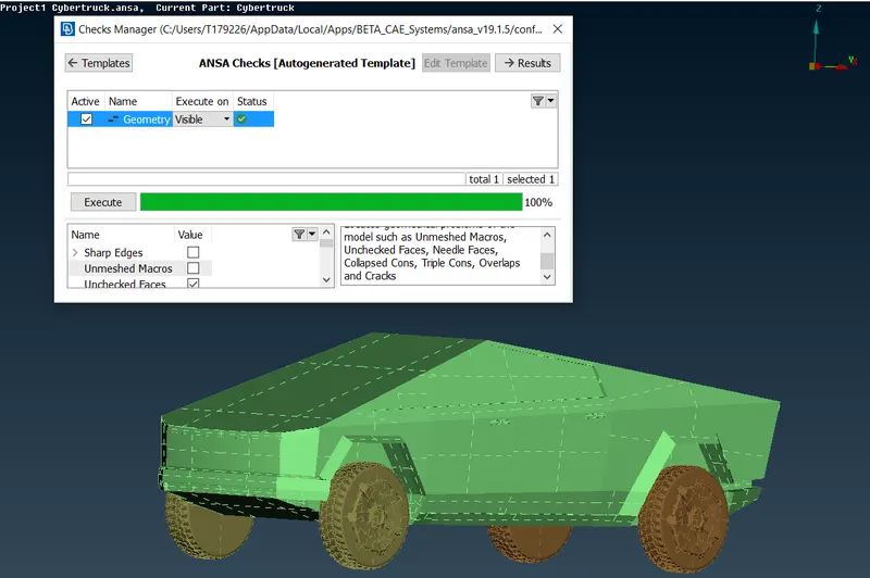
PID's Assigned
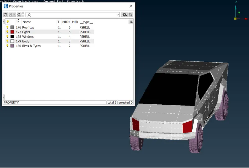
STEP 2- 2D MESHING
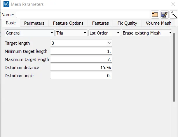
Mesh length for differnt PID's
Roof top- 3mm
Lights - 2mm
Tyres - 2mm
Windows -4mm
Body- 5mm
Lights meshing:
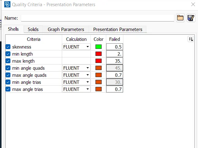
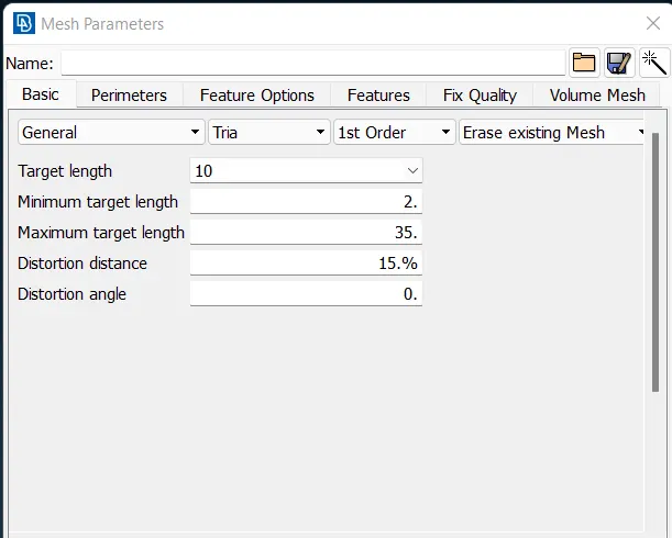
Quality criteria and mesh parameters for light
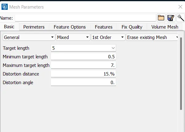
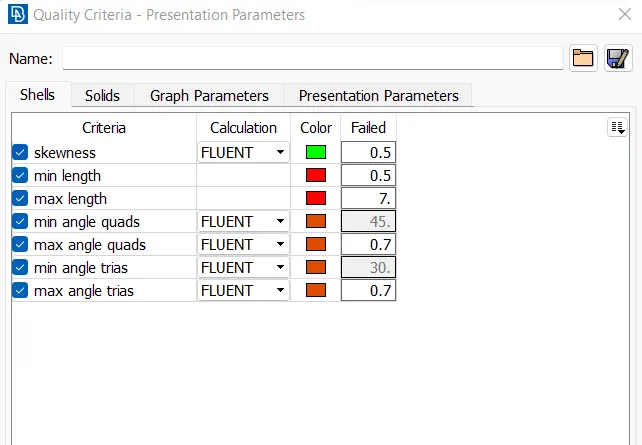
- Mesh length is 5mm
- After giving quality criterias, give length parameters and macros
- select length parameters and choose PID by doing right click and dragging cursor over PID. Then do middle click
- Dialogue box will appear, give mesh length 2mm and click ok
- Similar do for macros
- Then select spot mesh and choose visible mesh, you can see mesh on PID
- In order to check if geometry is failing on quality criteria go to hidden mode and go to entity mode while using hidden mode.
- you will off elements. select reconstruct option and choose visible and execute reconstruct option. Reconstruct option will solve most of off elements and remaining off elements needs to be solved by findind why mesh is failing, mainly this happens due to formation of meshes smaller than specified criteria.
- Go to topo mode and use cut options to cut or recreate cons where mesh is failing.
- Use reconstruct option to automatically solve maximum errors, rest handle by yourself.
- use move tool to change dimension of mesh , this will solve most of off elements, specailly those off elements which are due to min & max length.
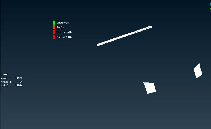
BODY MESHING:
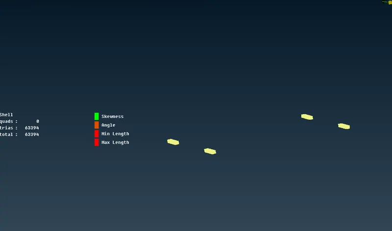
Quality criteria and mesh parameters for Body
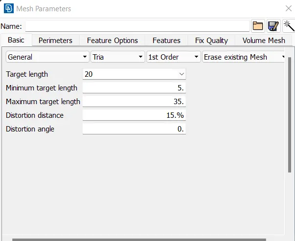
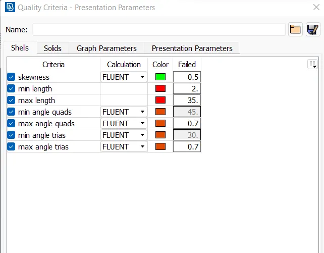
- Mesh length is 20mm, use high value of mesh because geometry has large dimensions.
- After giving quality criterias, give length parameters and macros
- select length parameters and choose PID by doing right click and dragging cursor over PID. Then do middle click
- Dialogue box will appear, give mesh length 2mm and click ok
- Similar do for macros
- Then select spot mesh and choose visible mesh, you can see mesh on PID
- In order to check if geometry is failing on quality criteria go to hidden mode and go to entity mode while using hidden mode.
- you will off elements. select reconstruct option and choose visible and execute reconstruct option. Reconstruct option will solve most of off elements and remaining off elements needs to be solved by findind why mesh is failing, mainly this happens due to formation of meshes smaller than specified criteria.
- Go to topo mode and use cut options to cut or recreate cons where mesh is failing.
- Use reconstruct option to automatically solve maximum errors, rest handle by yourself.
- use move tool to change dimension of mesh , this will solve most of off elements, specailly those off elements which are due to min & max length. Using move tool will eventually solve 98% of off elements.
- To use move tool identify areas where off element is and then drag meshes there too clear off elements.
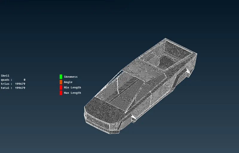
WINDOWS & ROOFTOP MESHING-
Quality and mesh parametrs for windows and rooftop.
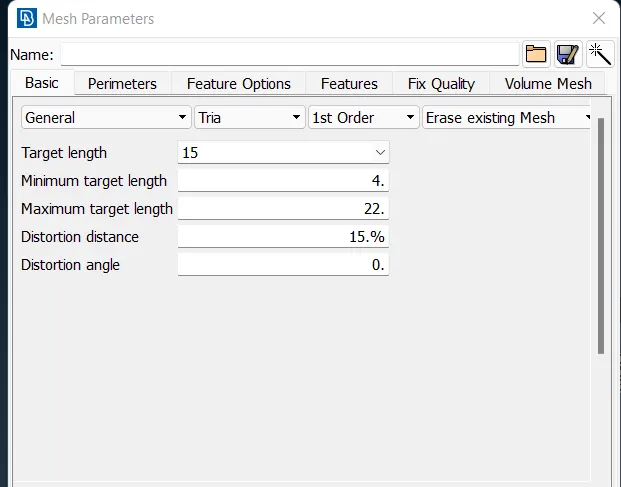
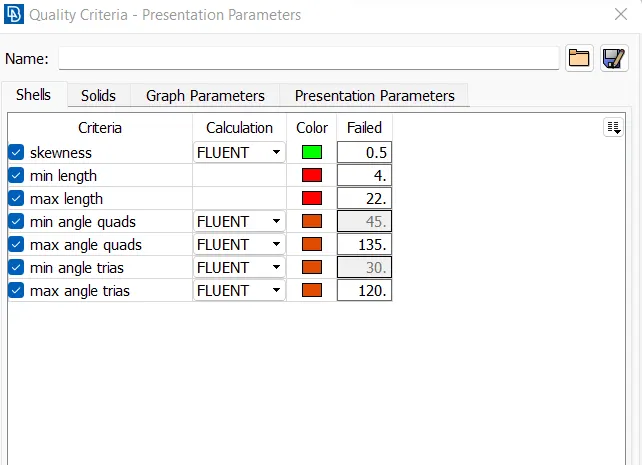

- Mesh length is 20mm, use high value of mesh because geometry has large dimensions.
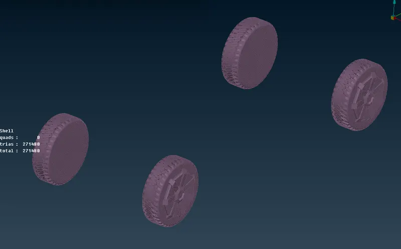
TYRES MESHING-
MESHING FOR DOOR HANDLE-
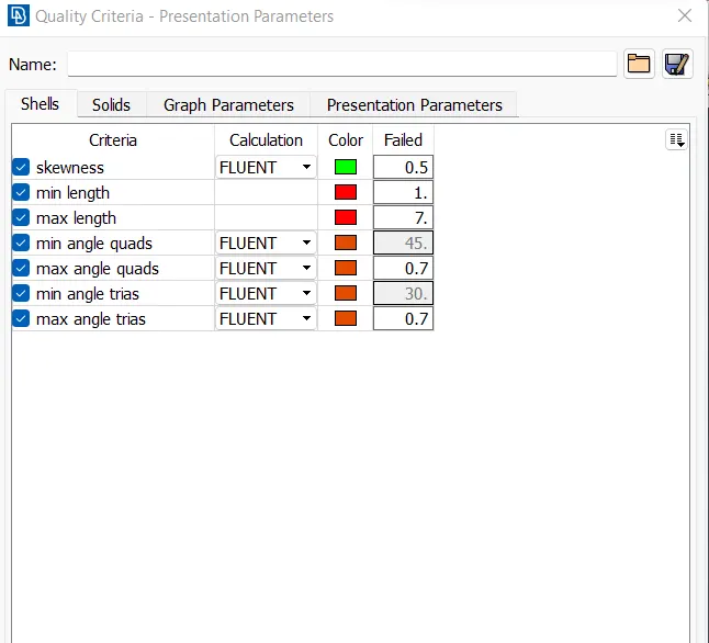
Door handle is a part of body but due to its small size I have meshed it with lower mesh length.
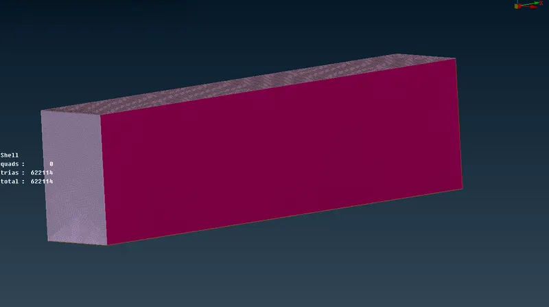
STEP 3: FORMING A WIND TUNNEL
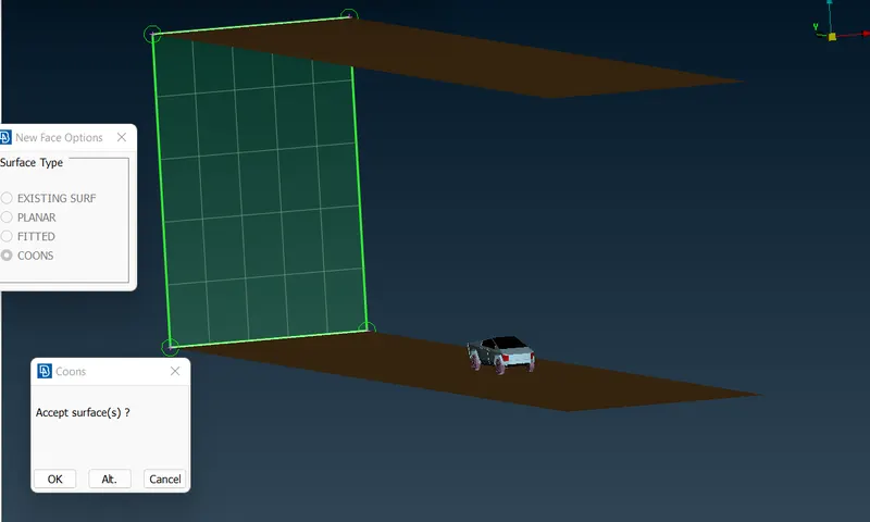
We'll build a wind tunnel around the vehicle.
The measurements used in wind tunnels are
Think of the car's length as X.
Keep the wind tunnel 75 mm away from the car's bottom.
The length of the wind tunnel from the front of the automobile should be 4X; the length of the tunnel overall is equal to half the length of the car plus 4X.
The wind tunnel should extend 6X from the back of the vehicle, with the total tunnel length from the rear side equal to half the vehicle's length plus 6X.
Height of wind tunnel must be three times the size of an automobile.
Car length is 5760.
2570 from the middle of the car to the front.
3180 from the middle of the automobile to the back
Steps required
- Add negatives
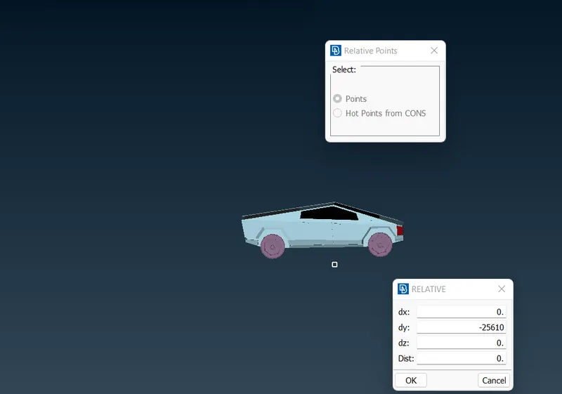
- Choose the relative points option in the point tool, then choose a point on the bottom side of the car in the middle.
- See your coordinate axes in the dialogue box that will display. I'll add 700 mm with a negative sign to make a point at
- the bottom of the car.
- Create a point with reference to that one at a distance of 25610 mm in the X direction from the front of the car and 37740 mm from the rear.
- On the front and back sides, construct side ponits with ATR 5760.
STEP-4 3D Meshing
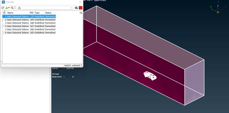
- Choose the define option from the volumes tool, then pick wholedb (the entire database), and then click "ok."
- A dialogue window with the volumes made for 3D meshing will emerge.
- Choose the first volumes option in the dialogue box; this is the volume of the tunnel and is what we need.
- The other volumes are all automobile volumes, so remove them all.
- We will keep the blue-colored PID and delete the others.
File link:
https://drive.google.com/file/d/1PYrPhnLIdWnS4Z9c1ToUM-yN2Gcw7t6j/view?usp=share_link
Conclusion:
- Working on the Tesla model provided insight into the various meshing technologies offered by ANSA.
- learned geometry cleanup and surface meshing in great depth. Problems encountered improved understanding of tools
- learned how to design a win tunnel using points and curves and how to use the curve tool
- learned about wind tunnel dimensions, such as what measurements to supply dependent on model size.
- learned how to utilise the rebuild and move tool, worked on how to correct off elements, and learned how to de mesh
- when there are various PIDs with varying mesh lengths in touch with each other.
preliminary topo-cleanup.