Project 1 : CFD Meshing for Tesla Cyber Truck
AIM :
To solve all geometrical errors and perform meshing of the Tesla Cybertruck geometry.
OBJECTIVES :
- Check and solve all geometrical errors for the given model.
- Assign appropriate PID’s to the various components of the truck.
- Perform meshing with suitable target length of choice and element quality criteria.
- Create a wind tunnel geometry around the cybertruck and write a detailed report of the procedure.
PROCEDURE :
The first and foremost step in geometry preparation is importing the geometry into ANSA. We can observe that the geometry contains single CONS on all the surfaces and thereby, we run the ‘topo’ function on the entire geometry.
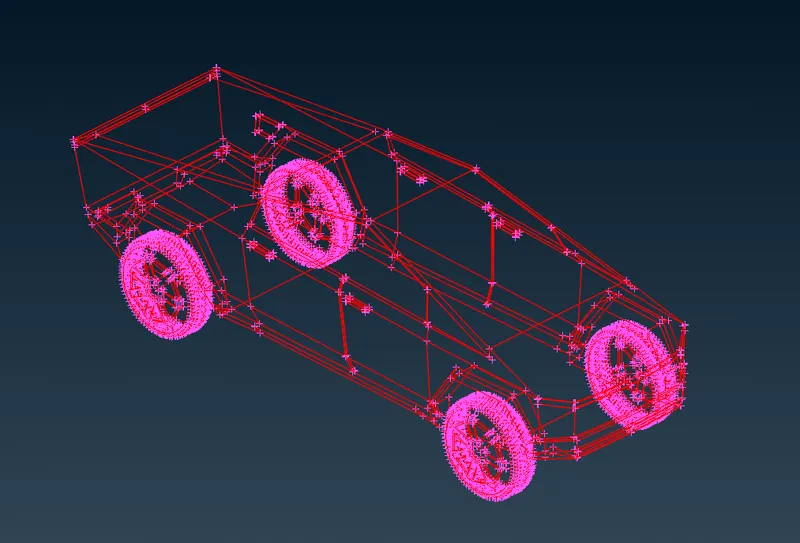
Our imported geometry is as shown. From the surfaces, we can observe that there are various missing surface errors which we need to solve one by one.
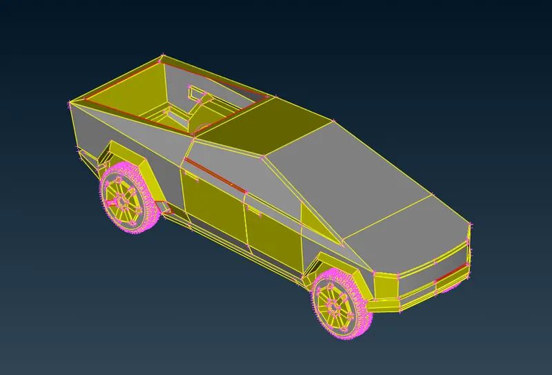
TOPO CLEANUP
In order to solve these errors in the geometry, we first split the body of the cybertruck in half as it is an axi-symmetric model. We do this by using the ‘plane cut’ function and selecting three hot points along the middle of the geometry so as to split the geometry. We delete the section of the geometry with more errors and retain the portion with considerably lesser errors.
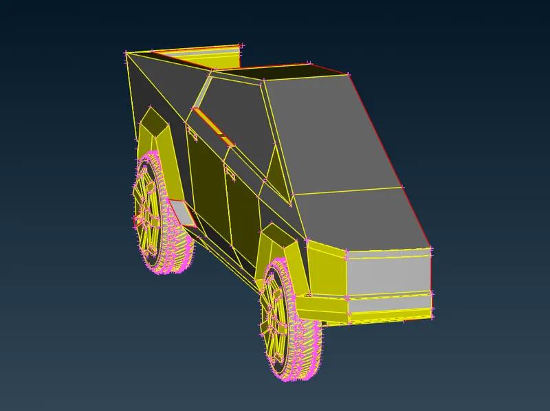
First, we create new faces over the missing surfaces of the geometry, thereby eliminating a few of the single CONS present.
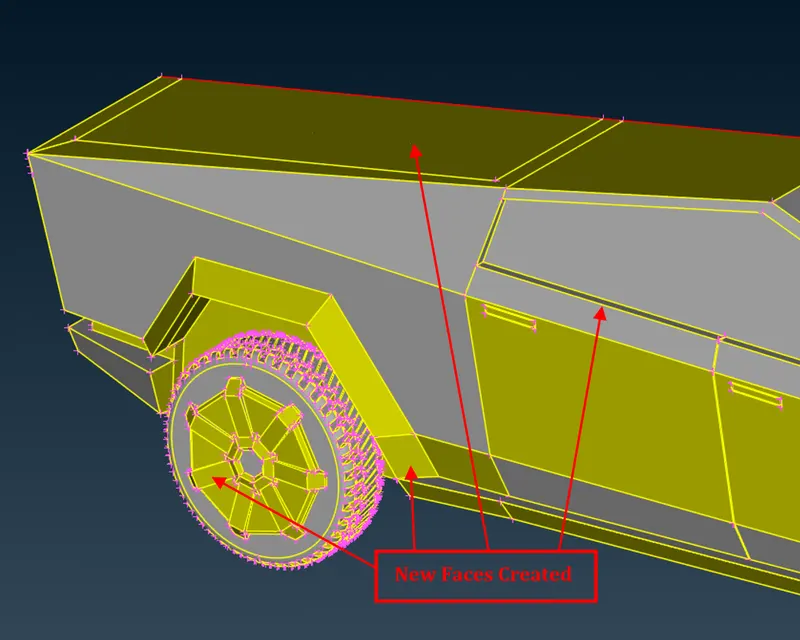
In order to obtain a good mesh, we need to refine the geometry to get rid of small edges and sharp corners as such. In order to do this, we delete these small surfaces and create new faces over them, thereby solving them.
Before :

After :
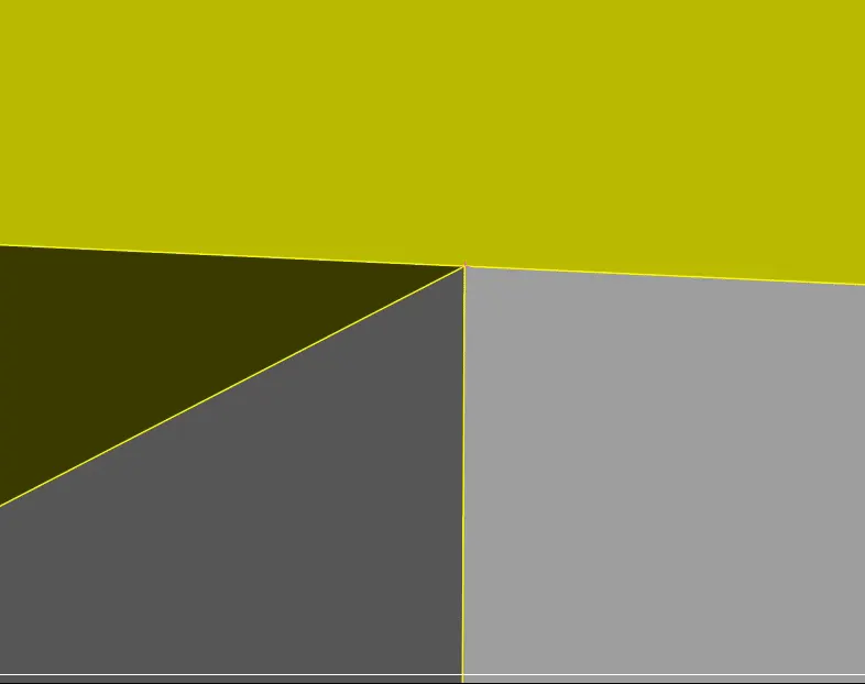
In the next step, we need to get rid of the intersection errors formed due to the overlap of two surfaces as shown. This is achieved by deleting the intersecting surfaces from the inner geometry and creating new surfaces so as to avoid intersection.
Before :
We can observe that there are three intersecting surfaces and sharp edges.
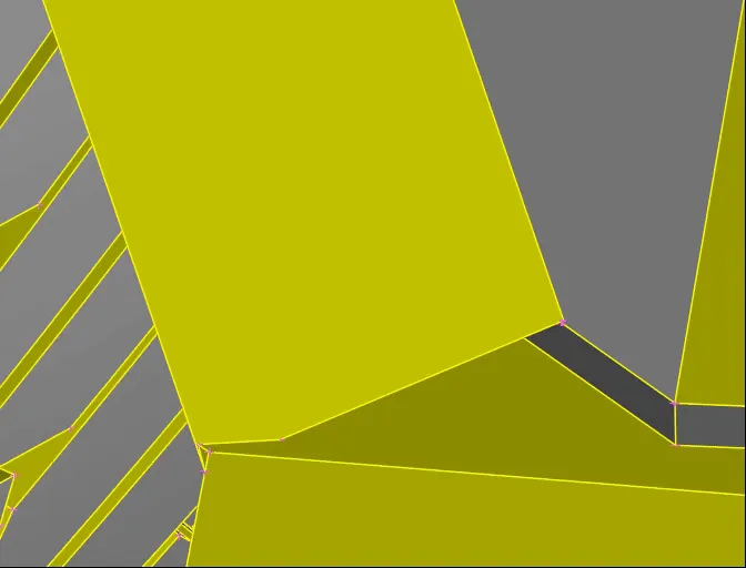
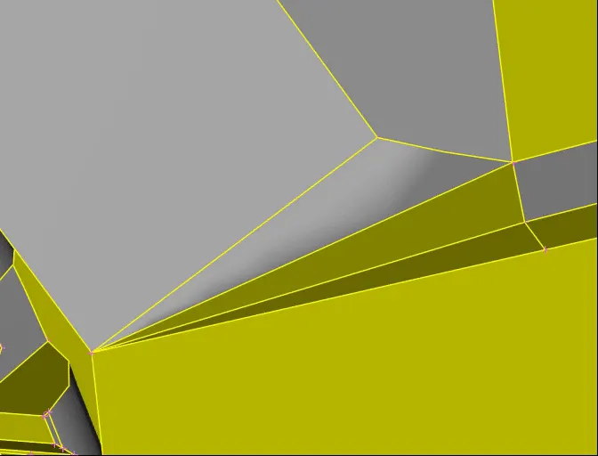
After :
The intersecting surfaces have been deleted and the geometry has been simplified.
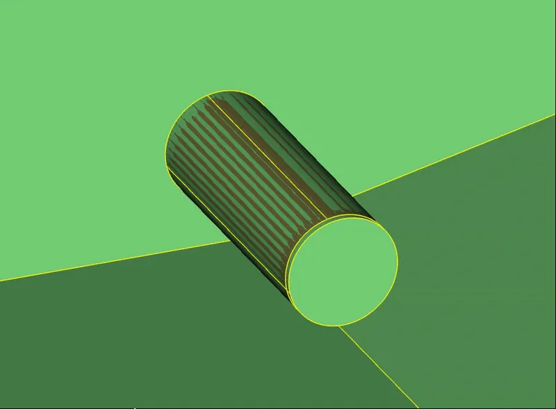
Now, to solve the intersection errors near the wheel shafts, we first clear the overlapping surfaces on the shaft and we delete the extra surfaces as well. Finally, we use the ‘fill hole’ function to get rid of the single CONS and thereby solving the intersection error. We repeat this procedure for the rear wheel shaft as well.
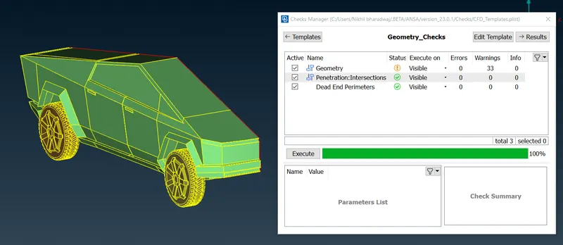
We run a final geometry check to make sure that there are no more intersection errors in the geometry. The single CONS on the cut plane of the geometry are acceptable as we are going to mirror the geometry along that surface and thereby solving them.
ASSIGNING PID’S
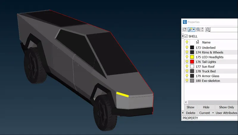
After all the geometrical errors in the geometry have been resolved, we then move on to assigning PID’s to the respective components of the truck. The assigned PID’s are as follows.
MESHING
After the respective PID’s have been assigned to the components of the cybertruck, we then move on to generate surface meshing for the geometry. We assume various target lengths for various components of the geometry as follows.
1.] LED Headlights & Tail Lights = 5 mm
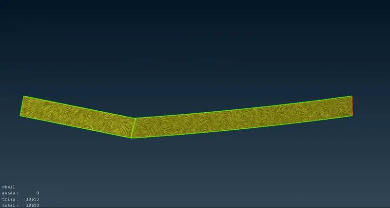
We first isolate these geometries and provide Auto CFD spacing of minimum length 3 mm and a maximum length of 7 mm such that the mesh transition with the body is smooth. We provide the quality criteria of the same range as well and we obtain the meshed geometries as follows.
2.] Rims & Tyres = 5 mm
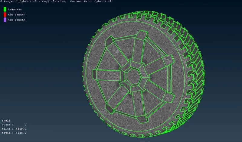
For these components, we generate tria CFD meshing for an element size of 5 mm. We provide the minimum length as 4 mm and maximum length as 6 mm.
3.] Body & Underbed = 7 mm
For these components, we provide a minimum length of 5 mm and a maximum length of 9 mm and generate CFD meshing.
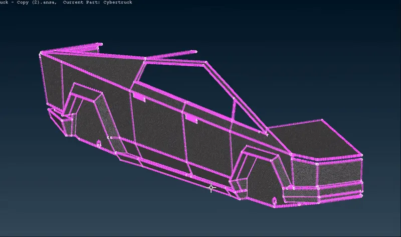
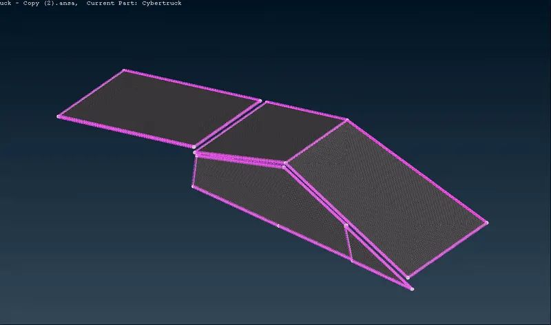
4.] Sunroof, Armor Glass & Truck Bed = 8 mm
We provide a minimum length of 6 mm and a maximum length of 9 mm and generate tria CFD meshing for these components as shown.
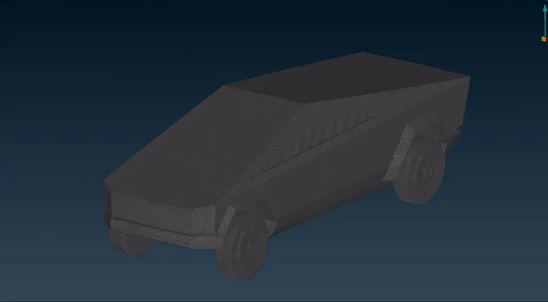
The final meshed cybertruck geometry is as shown.
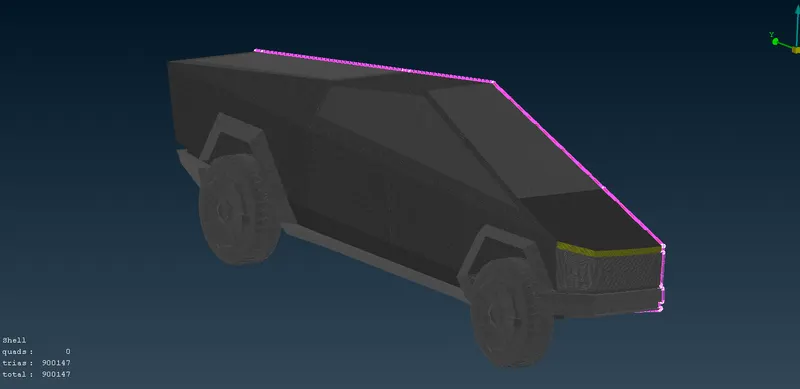
MIRRORING
In this step, we mirror the half geometry of the Tesla Cybertruck, along the cut-plane so as to obtain our complete geometry as shown. We use the ‘3 point symmetry’ option and select three random hot points along the cut plane so as to obtain the mirrored surface.
Geometry View :
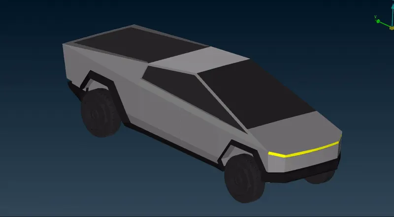
Mesh View :
WIND TUNNEL CREATION
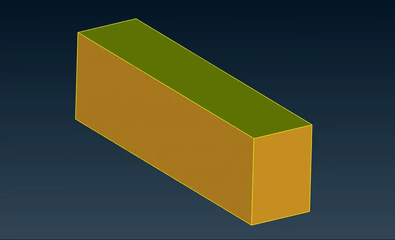
After the geometry preparation and meshing has been carried out, we then move on to create a wind tunnel geometry around the cybertruck. The dimensions of the windtunnel are as follows.
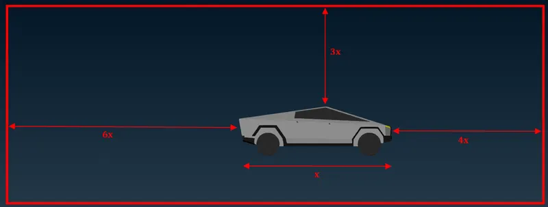
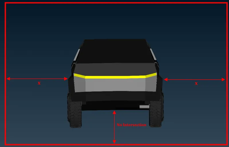
With reference to these dimensions, we create the bottom face of the wind tunnel by projecting nodes at the respective distances.
Here, ‘x’ is the total length of the cybertruck.
x = 6000 mm
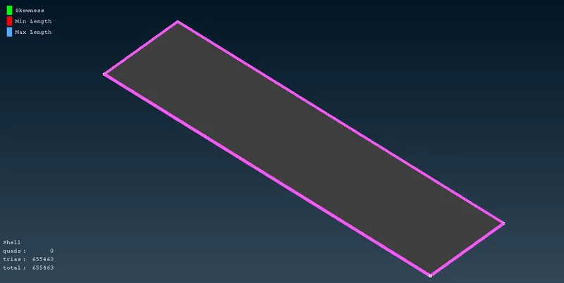
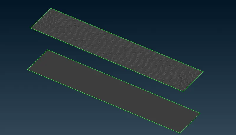
The bottom face is created as shown. Finally, we generate CFD meshing of a target length of 50 mm for the bottom face as well.
By taking the bottom face as a reference, we create the top face at a distance of ‘3x’ from the top of the cybertruck. We generate CFD meshing for a target length of 150 mm for the same.
Finally, the side faces of the wind tunnel are created which enclose the car geometry inside it. The side walls are provided with a growing mesh starting from 50 mm and growing to 150 mm.
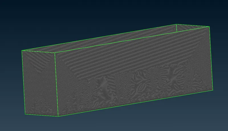
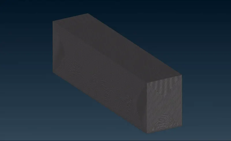
The final wind tunnel geometry is as shown.
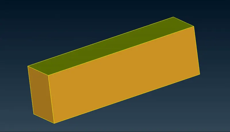
360^o View of Final Model :
1. Mesh View
2. Geometry View
Final Model File : https://drive.google.com/file/d/1dN7rzjh-d0sPBEISAoGCINeORhiwLuxn/view?usp=share_link
CONCLUSIONS :
Topology cleanup has successfully been carried out for the Tesla Cybertruck geometry and all the errors and missing surfaces have been resolved and have been explained in detail.
Various components of the truck have been meshed for different target lengths while maintaining the quality criteria. A wind tunnel geometry has been created around the truck geometry and surface meshing has been generated for the same.