Project 1 : CFD Meshing for Tesla Cyber Truck
PROJECT 1 : CFD MESHING FOR TESLA CYBER TRUCK
AIM:
- To check and solve all geometrical errors for the given model.
- To assign appropriate PIDs.
- To Perform meshing with the suitable target length.
- Target lengths for the different parts of a model can be decided by your own.
- To make all the 2D elements as trias in the model.
- To create the enclosure for the geometry (wind tunnel) around it.
- To clear the quality criteria.
- To write a detailed report of the project.
PROCEDURE:
1. Patch the missed surfaces:
- First we need to import the geometry model from the source folder.
- The geometry file contains lot of ir-regularities, discontnuities, so we need to patch all the missing and open surfaces in the geometry.
- This can be done by the following procedure;
TOPO → faces → new → here we can select any method → select the cons (this can be done by entity or PID method) → middle click or surface click.
2. Removing overlapped surfaces:
- At some areas of the geometry, we need to clear the overlapped surfaces.
- This can be done by following procedure;
TOPO → delete → select the surface to be deleted by using entity or PID mode.
- Sometimes we need to project the cons to make the single cons into triple cons.
- This can be done by the following procedure;
TOPO → cons → project → select the cons → middle click → select the face where the cons has to be projected → middle click.
3. PID assigning:
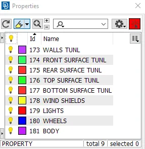
- Now we need to create PID (Property ID) for all the surfaces like inlet, outlet, spring, column, base and valve head.
- This can be done by the following procedure;
Properties → right click on the properties screen → new → PSHELL → PSHELL → box pops-up → name has to be given.
- Similarly we need to create as many as required.
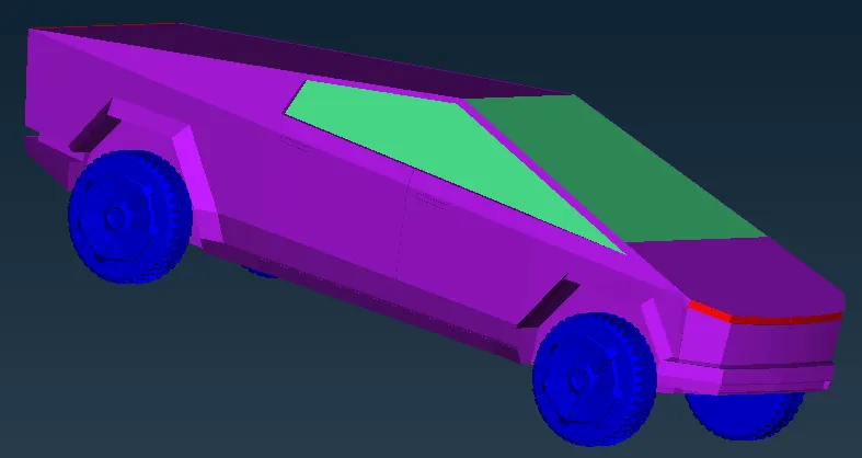
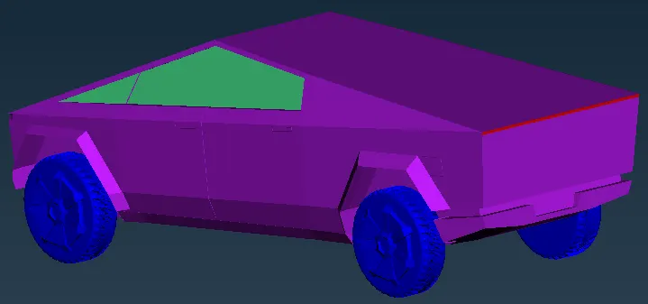
- Now we need to assign the created PID 's to the respective surfaces required and we need to make sure that cross-hatches option is enabled.
- This can be done by the following procedure;
Properties → right click on the PID → apply → select the cross hatch present in the surface of the geometry → middle click on the mouse.
- Similarly we need to do for all the required surfaces.
4. Surface mesh process:
Target lengths used for the different parts of a model are as follow:
- Body - 4 mm
- Lights - 1 mm
- Rims and Tyres - 3 mm
- Wind shields - 3 mm
- Enclosure - 100 mm
- Now we need to mesh the geometry.
- This can be done in two ways;
- Meshing the whole geometry in one shot. (only with single element length can be done at a time)
- Meshing the geometry part by part individually. (each part or component can be given different element length)
- The first method is employed in this challenge, however the second is highly beneficial when meshing distinct pieces with varying target lengths.
- Messhing can be done by following procedure;
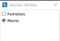
MESH (right side on the screen) → perimeters → length → perimeters → give the target length → ok.
MESH (right side on the screen) → perimeters → length → macros → give the target length → ok.
Mesh parameters (Top of the screen) → give the target length, min and max length in that dialog box.
Quality criteria (Top of the screen) → give the target length, min and max length in that dialog box.

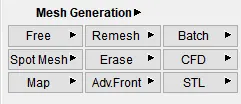
Mesh generation (right side on the screen) → spot mesh → select the geometry to be meshed.
5. Enclosure construction:
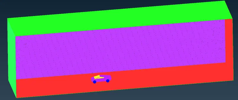
- Now we need to create a enclosure to the geometry which can aslo be called as wind tunnel.
- We need to take the mesurements of the car.
- Now we need to create a point, from that we need to extend our points.
- This can be done by following procedure.
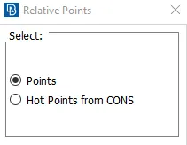
TOPO → points → relative → select the hot point and middle click → specify the direction (- or +) and distance →click ok.
 →
→ 
- We need to join the points created using the other tool
TOPO → curves → create → drag from one point to another → middle click → esc.
- Now we need to create the surface using the other tool.
- Now we need to create the similar surface on the top of the car using another tool.
TOPO → faces → offset → select the cons → middle click (arrow appears) → specify the the value.
- Now create the faces in the required places using faces tool.
6. Volume identification:
- Here we need to identify the volumes.
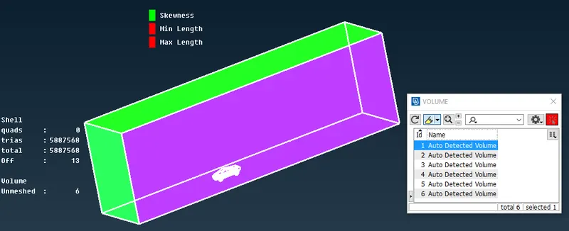
volume mesh → volumes → define → auto detect → work on → whole db → ok
- Totally eight volumes have been detected.
- wind tunnel + car → 1
- wheels → 4
- car body → 1
- We can keep first one and delete the rest all because it is unnecessary.
CLEAN-UP IMAGES:
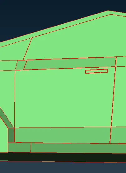
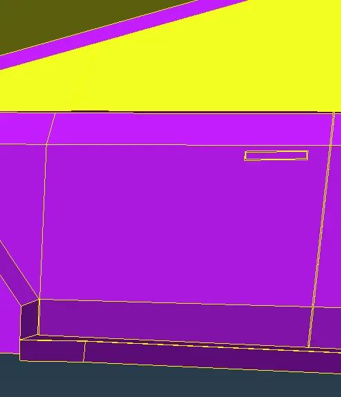
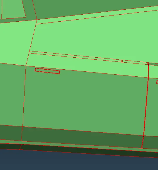
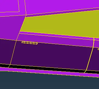
1. Front door left : Rectangle piece missing
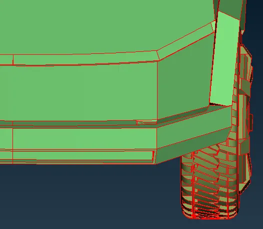
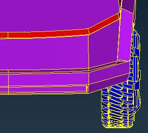
2. Front Near bonnet: Rectangle piece missing
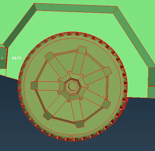
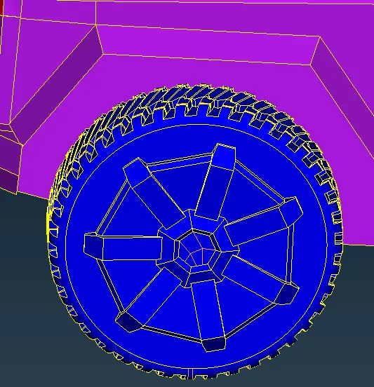
3. Front wheel left: Center piece missing
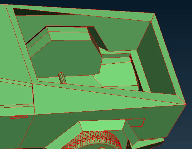
4. Back of the truck : Rectangle peice missing
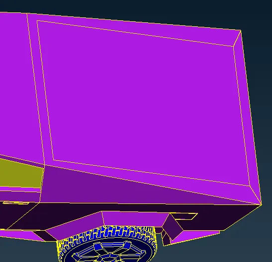
5. Right back door : small rectangle peice missing:
MESH IMAGES:
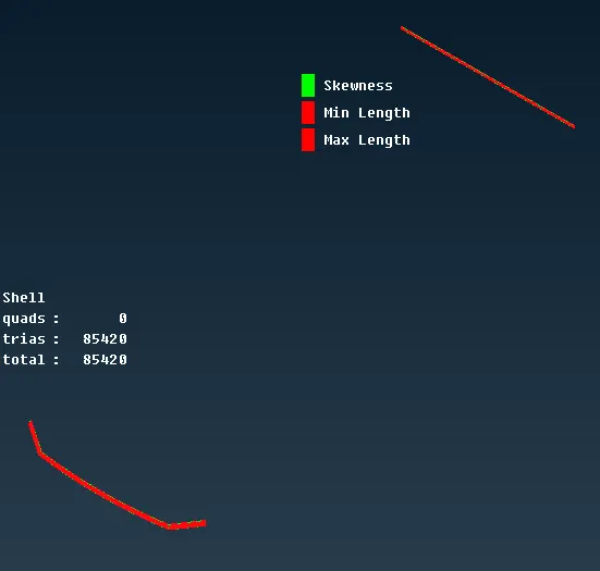
Front and back lights:
Car wheels:

Wind shields:
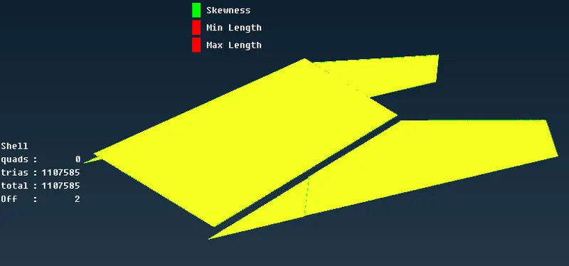
Car body:
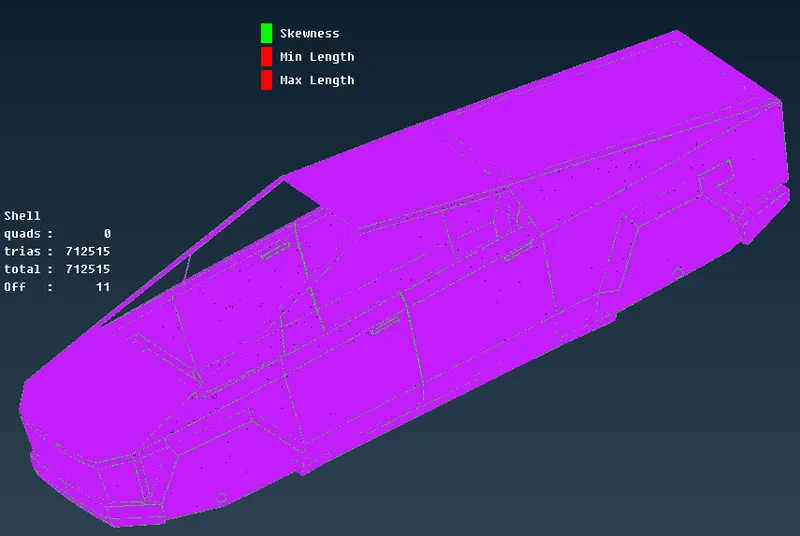
QUALITY CRITERIA:
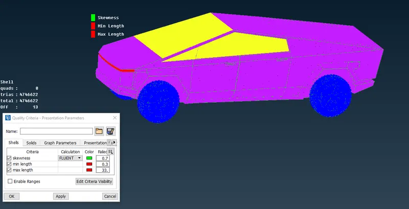
Whole car
- This mesh has been done by CFD method.
- Here the off elements are 13 in count.
- These 13 elements were unable to clear due to a software error, as the skew, min, and max elements were not observable by even changing their colour to identify them.
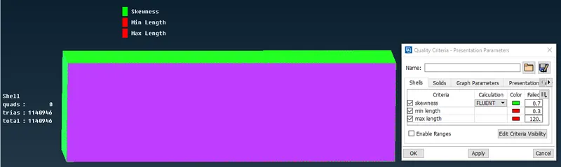
Car enclosure:
- This mesh has been done by CFD method.
- Here the off elements are zero in count.
CONCLUSION:
- The entire model is cleared without any ir-regularities, incomplete surfaces, single and triple cons.
- PID's are assigned for each components.
- The geometry and enclosure is perfectly surface meshed with different target lengths.
- The surface mesh is done with zero quad elements.
- The geometry file is attached to the report.
MESHED GEOMETRY FILE:
https://drive.google.com/file/d/115UwhSDqlupccyUKKiBDxGauu7h_wQ1B/view?usp=sharing