Project 1 : CFD Meshing for Tesla Cyber Truck
PROJECT 1:
CFD MESHING FOR THE TESLA CYBER TRUCK:
AIM:
To cleanup all the Geometrical errors and CFD Meshing on Cyber Truck. To create a simple wind tunnel and mesh it.
RESULT FILE LINK:
https://drive.google.com/file/d/1e12M0HMePI0bunYmREX540S8W7SsVrV3/view?usp=share_link
PROCEDURE:
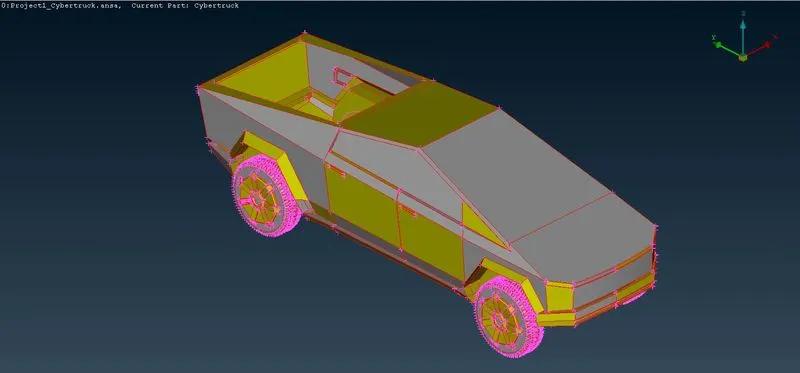
- First steps is to import the model into Ansa Workspace. and so we can work on the model.
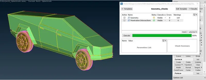
- We need to check for geometrical errors, so go for check geometry and execute it.
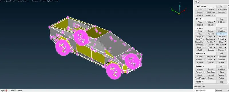
- As we cannot able to see the errors we can go TOPO option in the faces tab and select the model.
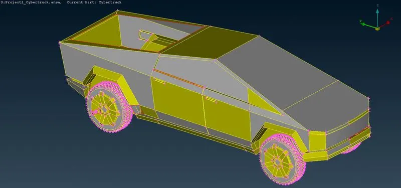
- After hitting up the topo option we can see there are some errors appeared in the model. so we can work on it now.
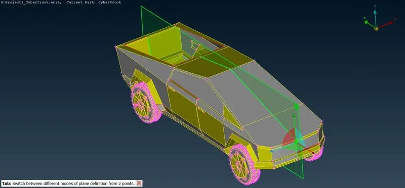
- As we can see that the truck is Symmetry, we can cut it into half part and work on it. using plane cut option select 3 points from start to end and click ok. now the truck is cut into half.
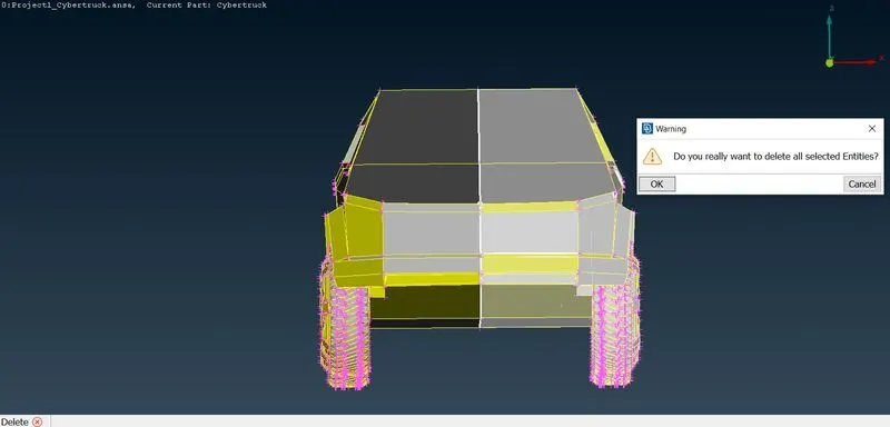
- So now we can delete the cutted half part, and can work on the remaining half.
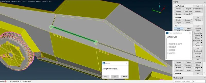
- Single cons are spotted on the window attachment part, so just create a nw surface over there and it will be cleared.
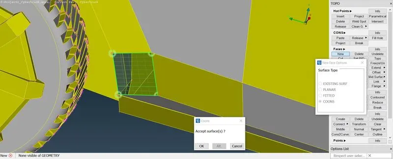
- Now single cons can be seen at the rear tyre's guard. just create a new face over there.
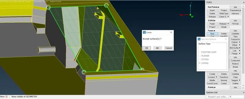
- At the back side of the truck a opening is there so just close it by creating a new face over there.
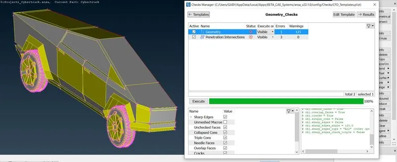
- As of now we can go check for geometrical error by executing check geometry. we are now able to see some errors appeared on the model. we will work on them.
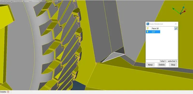
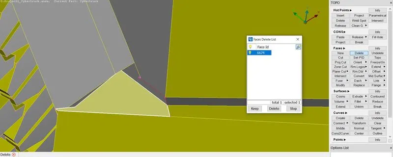
- There is intersection error at the tyres guard so isolate it and delete the intersecting part.
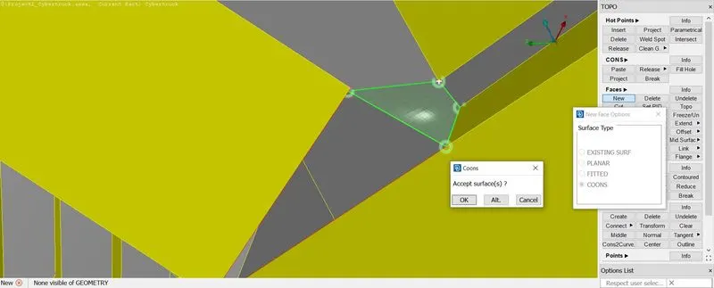
- Now we can create a new surface over the guard appropriately.
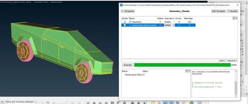
- Open the check manager and see for intersection error, we have to clear the intersecting errors.
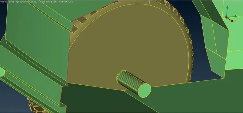
- We can spot that there are intersecting part over the wheel's connecting rod, so isolate the guard and check for errors over there.
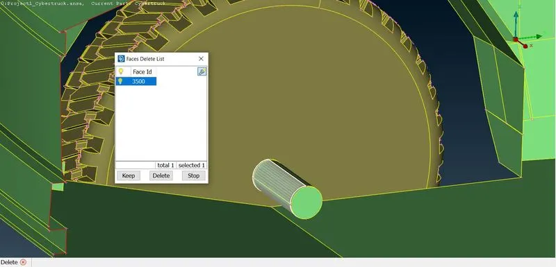
- Now we can see the overlapping surface on the connecting rod, so delete the surface.
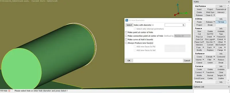
- After deleting the face there is single cons appears so we can close it by using fill hole option and select it and click ok. so do it for the other wheel too.
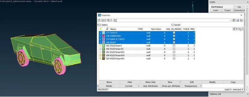
- As of now we cleared the errors now we can assign all the PID's we needed.
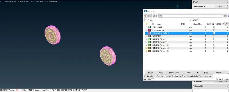
- First assign for tyres and rims, open pid in the upper deck and create new PID rename it as Rims and Tyres. now apply it to the Rims and Tyre isolated.
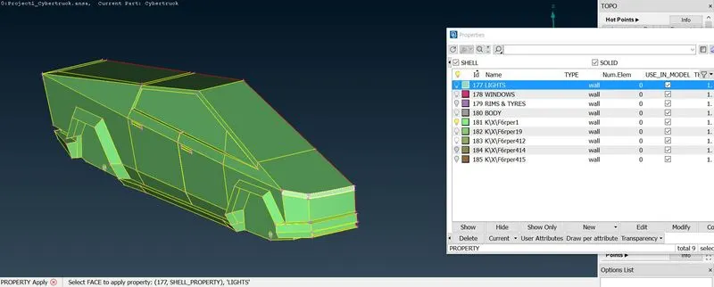
- Now do it same for the lights, and assign pid to lights.
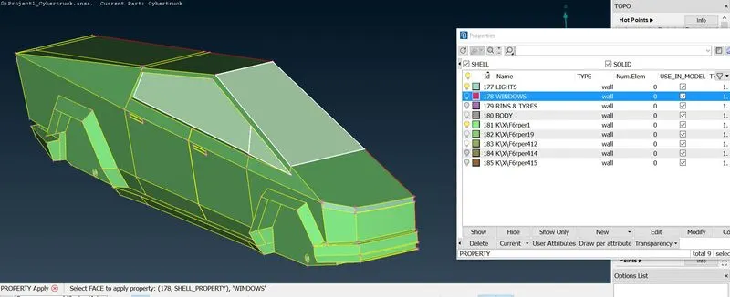
- So isolate the Windows as shown in the above fig and aplply Pid to it.
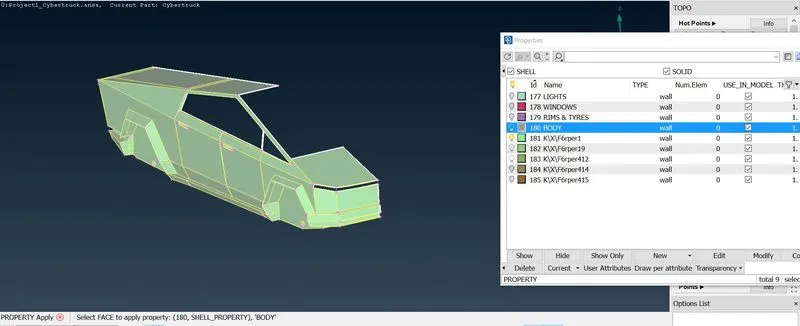
- Now hide assigned parts and assign for the whole body.
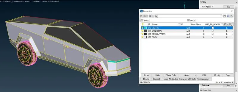
- After completion of assigning of pid's for the model, as shown in the above fig.
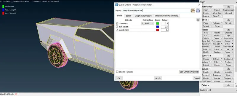
- Next we have to go for Quality Criteria option on the upper deck and select Skewness, Min & max length. and click apply and ok.
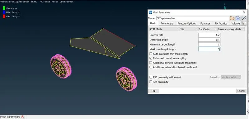
- Now isolate the windows and tyres as they both are of same mesh length and Next go for Mesh parameters, enter the required values, click ok.
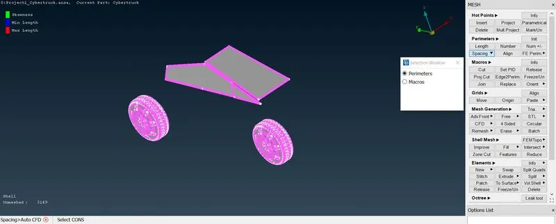
- Next go for spacing option and select auto cfd then select the entities of perimeter as shown in the above fig.
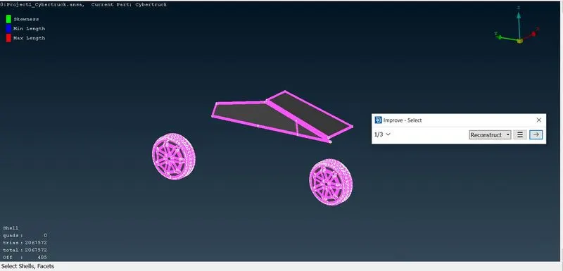
- After that go for Cfd Visible, now we can see the off elements, so right click on the off elements and select improve option to clear it, and click ok.
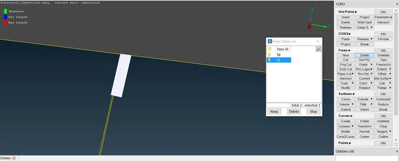
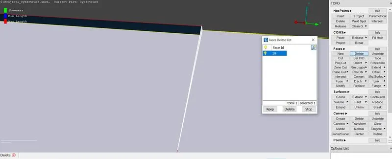
- After improve option carried out we can see there are skewness errors appeared over there s shown in the above fig. delete the innecessary face.
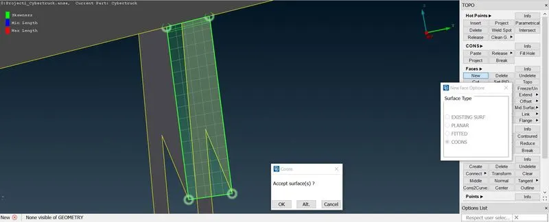
- Create a new face after deleting the surface over there.
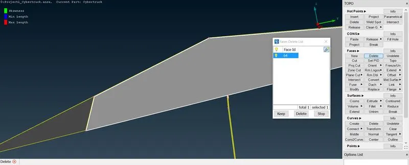
- We can see there is a small face so for clearer geometry delete the entire window.
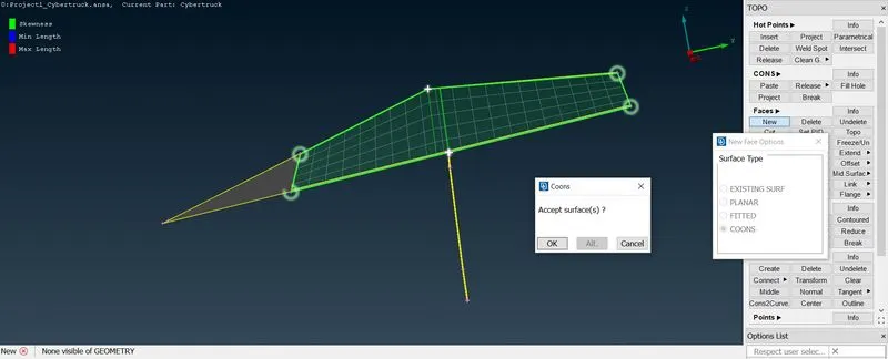
- Now we can create a new surface over the deleted surface.
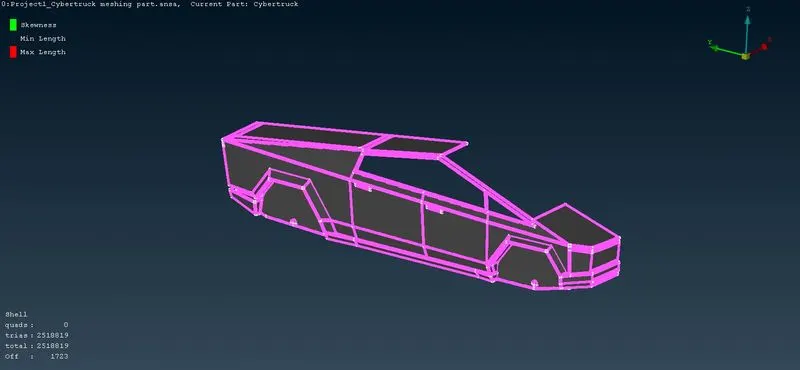
- Now go for the mesh parameter and enter the required value for the body and do the remaining procedures same as tyres and windows.
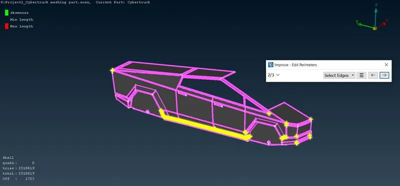
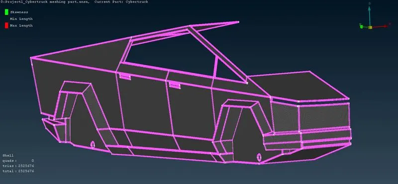
- After meshing the body we can see the off elements here also, so go for improve and do the same procedures. Now after cleared the off elements is shown in the above fig.
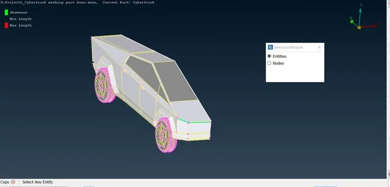
- After completing the meshing of parts, we have to create the other half of the truck, so opt for Transform option in the upper deck and select the entities as shown in the above fig.
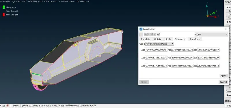
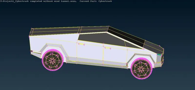
- now go for the 3 points mirror option and select the points from front to back and click ok, now the half part is created.
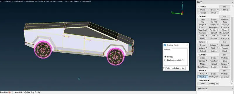
- After completing the transform of truck, we have to create a wind tunnel so insert a hot point at the bottom center of the truck and click relative option in the points tab and select the inserted hot point and enter the value required and click ok.
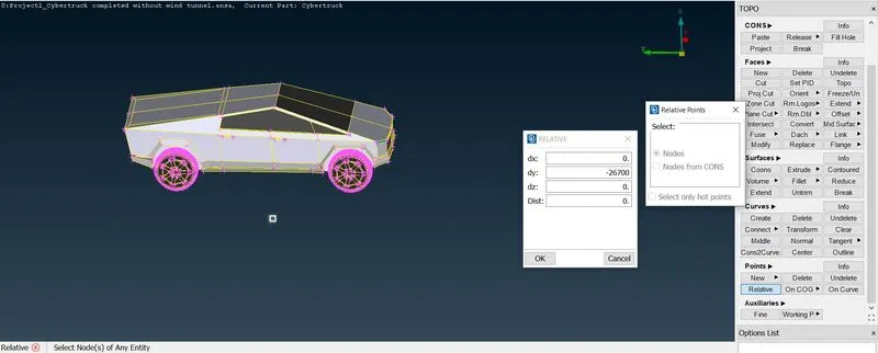
- Now do it same for the front point to be created but enter the value in the negative Y direction for front and click ok and next enter the required value for the back point and click ok.
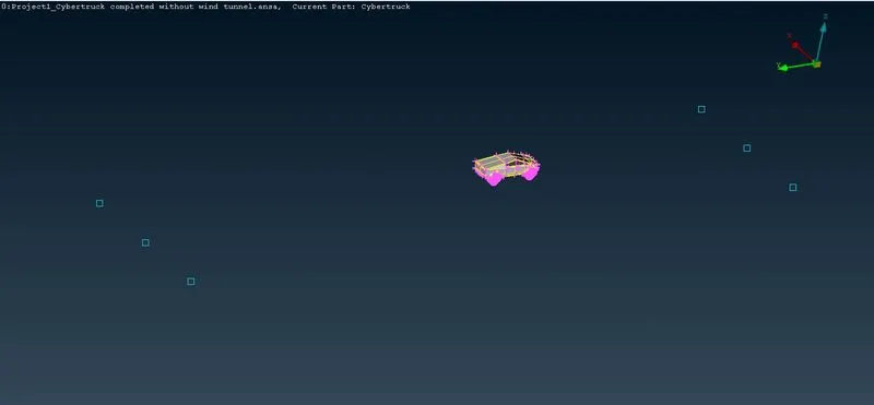
- After creating the required points, now select the front and back points and again go for relative now enter the distance for the left and right side to the curve to be created. now we can see the completed points.
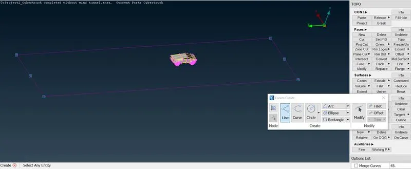
- Right after creating the points that are enough to create a curves over there, now create a curves on the created points.
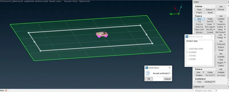
- So now create a surface over the created curves.
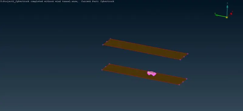
- Now select the off set option in the faces tab and select the bottom face and enter the distance the other face to be created. and click ok. now the face is off setted to the entered distance.
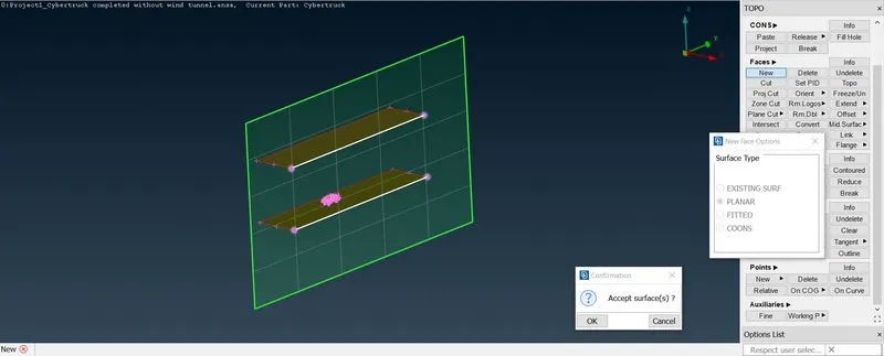
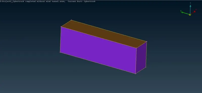
- so we can easily create the side surfaces by selecting the top and bottom faces create the faces all over the sides.
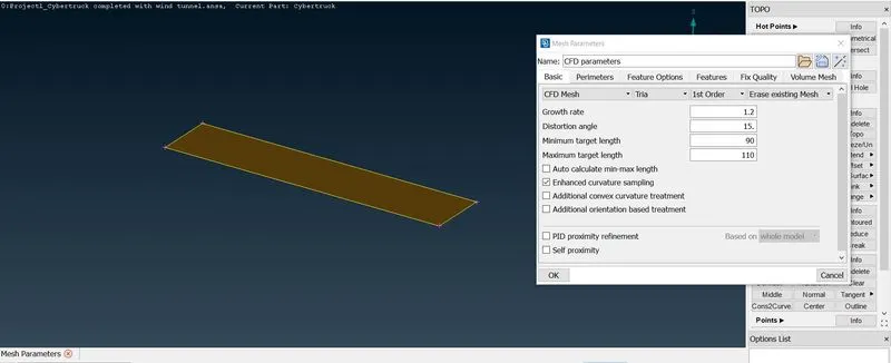
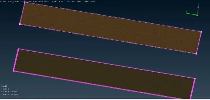
- Now isolate the bottom face created and assign mesh parameters as required and click ok. do the remaining procedures and mesh the top face also. after mesh both the surfaces as shown in above fig.
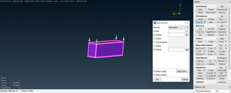
- After meshing both the faces we have to opt for growing mesh for the side surfaces. so go for spacing and manual option and select the four corners at the botton as shown in the above fig, now enter the required dstart value and dlimit value and click ok.
RESULTS:
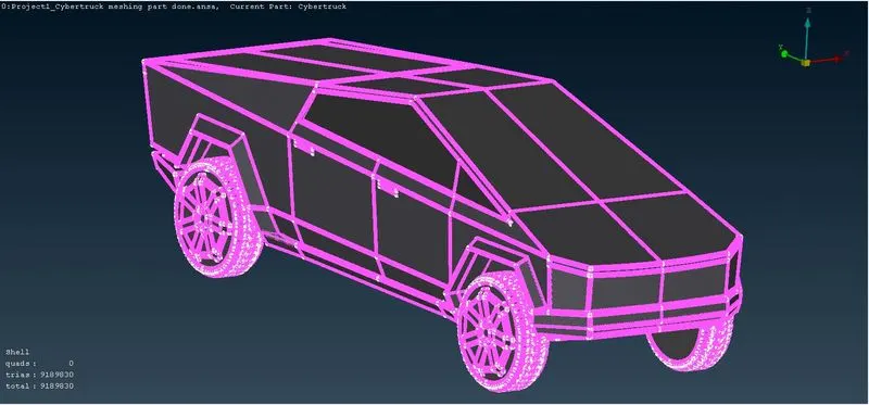
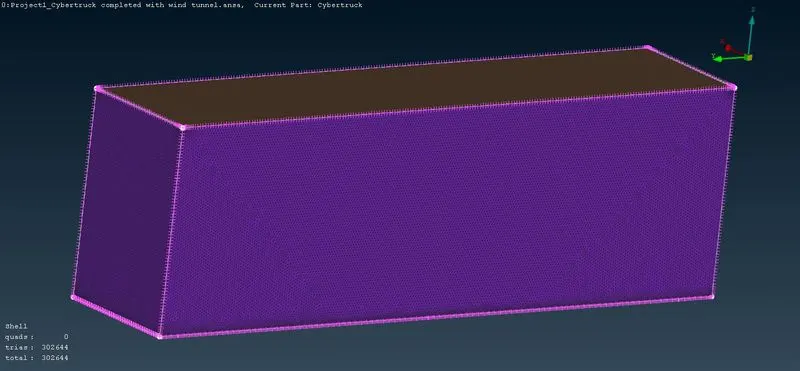
- Now the given project is completed finally.
CONCLUSION:
- In this project i have learned to cleanup all the errors and able to mesh the cyberTruck.
- Also created simple Wind Tunnel and have mesh it on my own.
- Gained some knowledges on how to work on projects and complete it.