Project 1 : CFD Meshing for Tesla Cyber Truck
Aim : CFD Meshing of Cyber Truck with Different Meshing length for different Parts.
Proecedure : standard procedure is geometrical cleanup there after remove all intersection error nad geometry error then meshing as per meshing length.
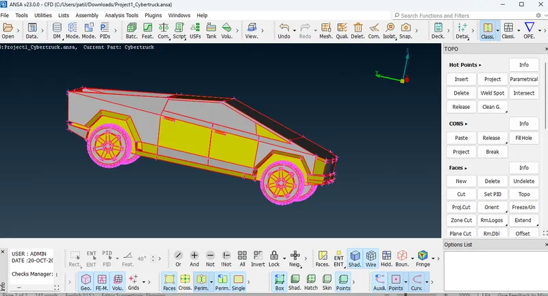
We can see in fig geometry shows all red coons,intersection error,surface missing, so it is necessary to do topo, after hit topo geometry lookslike fig no 4.
Topo : Face topo fix error, and remove extra hot points.
. 
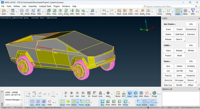
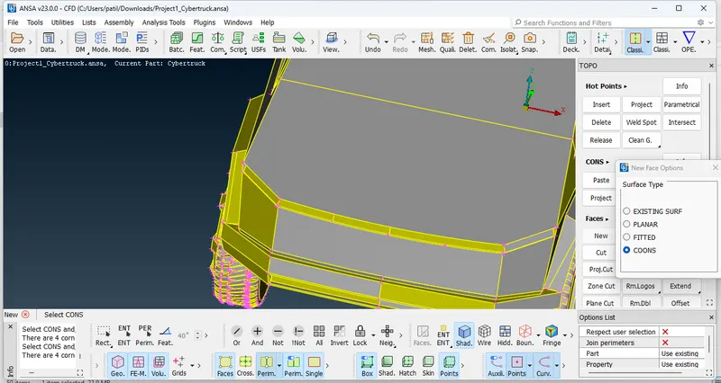
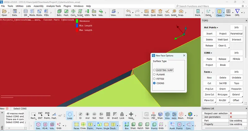
some red coon we can see that means there is surface missing, we are going to create new surface.
Topo Deck> Face > New Face> Coons.
Whenever we are going to create surafce got options like face coons, Planar surface, existing surfac, use suitable option accordingly shape of geometry.
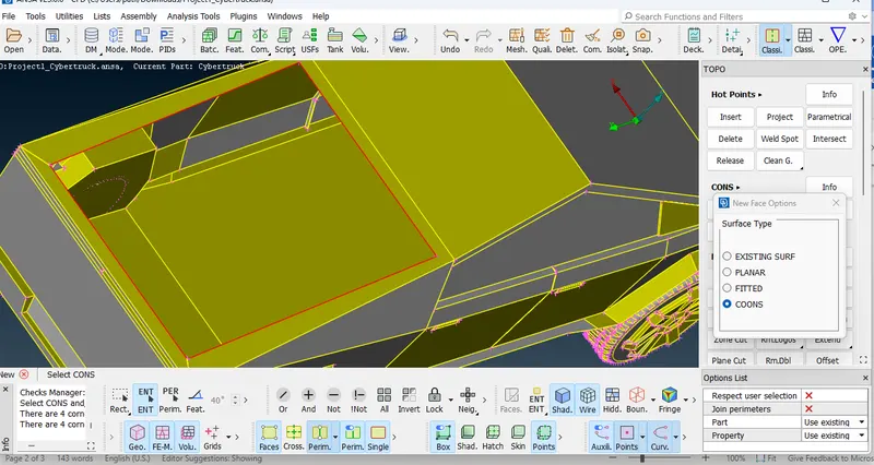
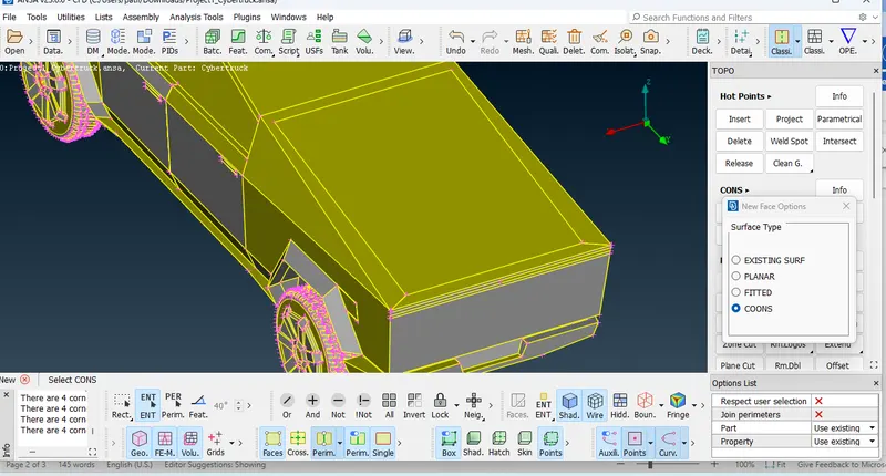
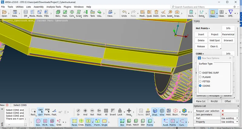
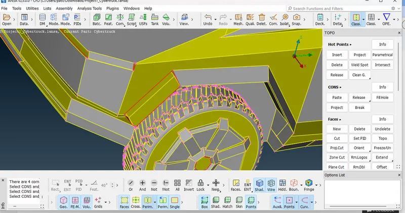
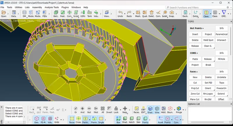
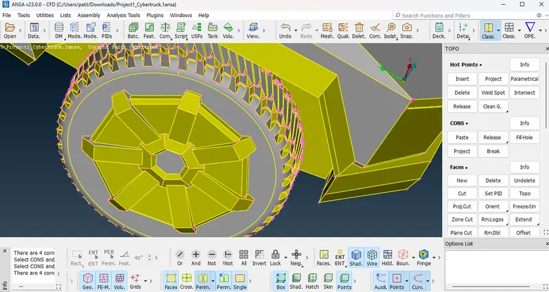
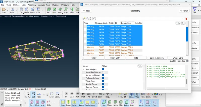
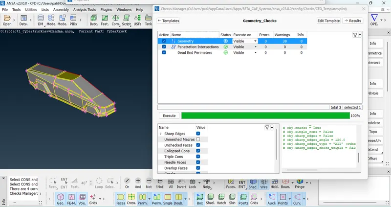
while considering geometrical cleanup ensure that geometry should free from red coons triple coons, single coons.
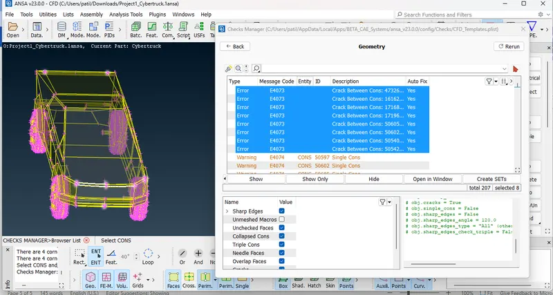
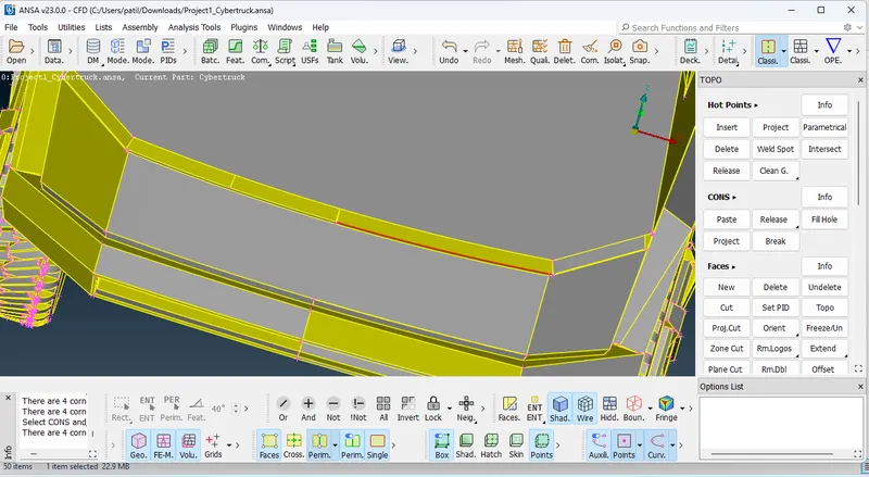
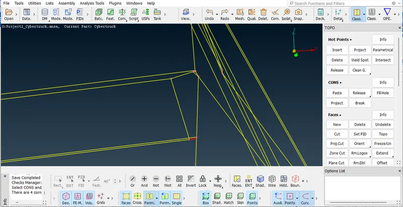
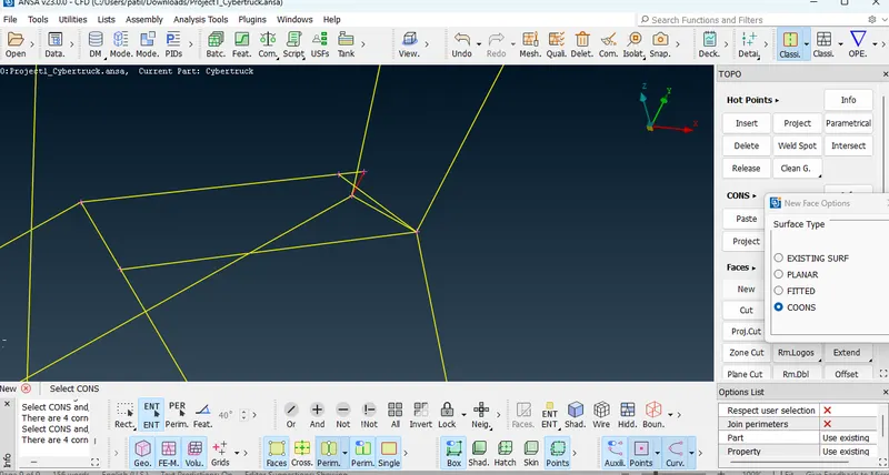
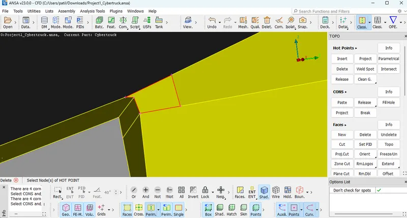
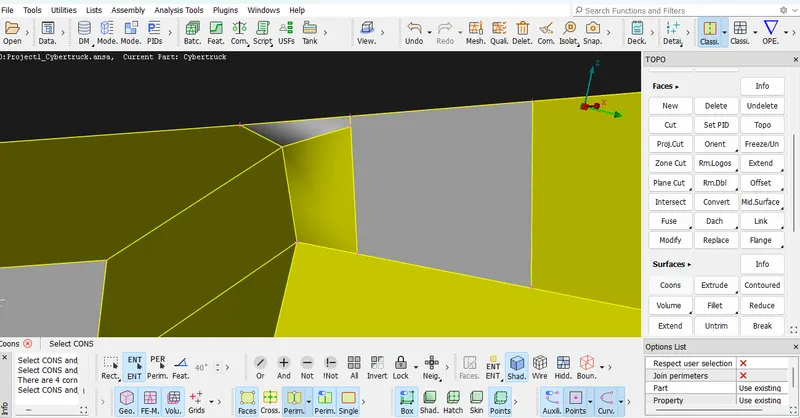
Crack error appears when coons are not connected properly hence while create new surface select the coons properly.
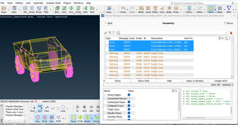
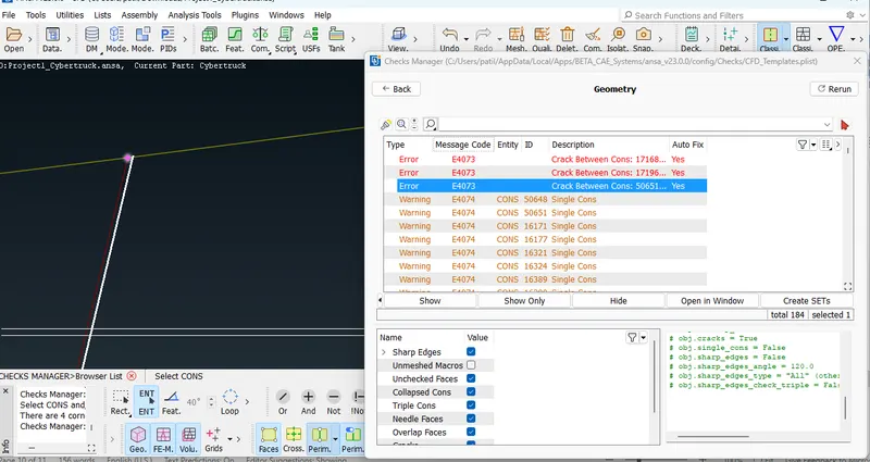
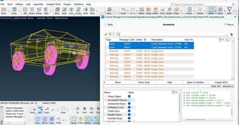
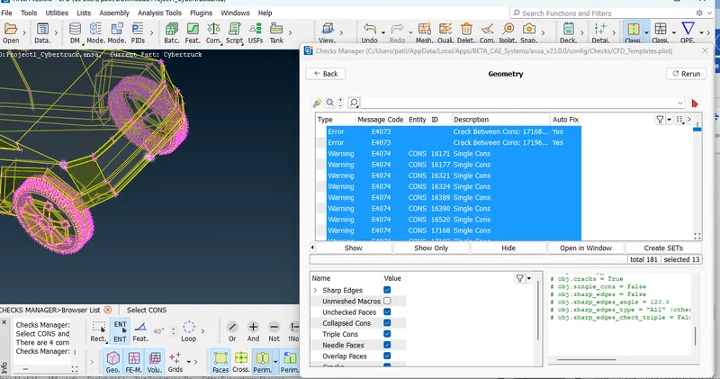
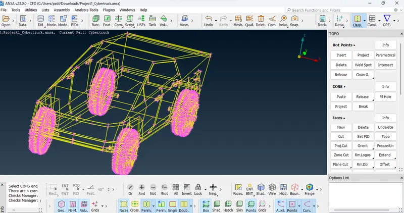
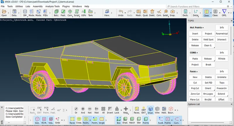
We can see in result after clear all red coons and crack, single coons.
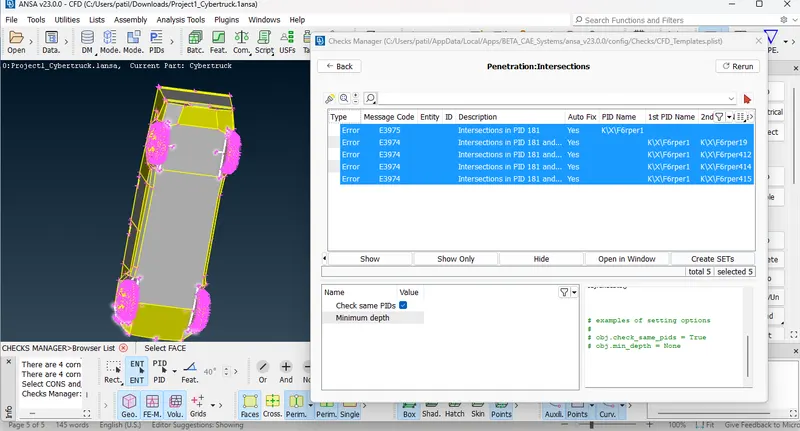
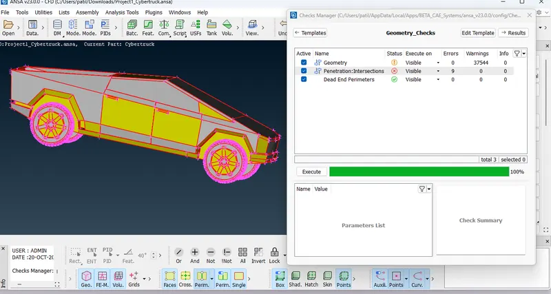
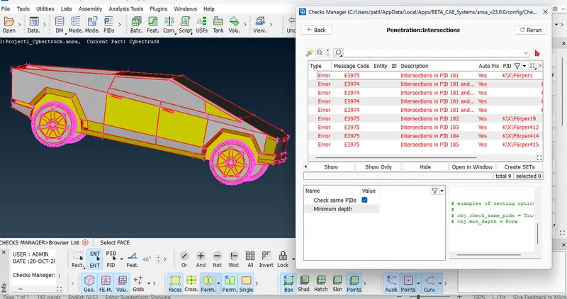
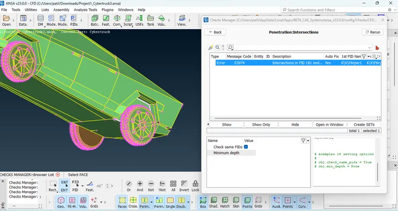
Intersection error : it occurs when parts are intersecting with each other make sure while doing meshing geometry don't have any intersection error.
If we can observe closeley bumper part of truck is highlighted
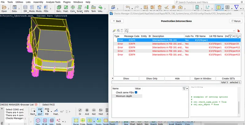
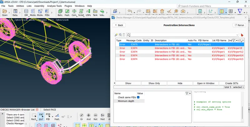
This intersecting error appear due to this part intersect to tyre guard, for remove this error delete this part and create new surface with new face as shown in below fig.
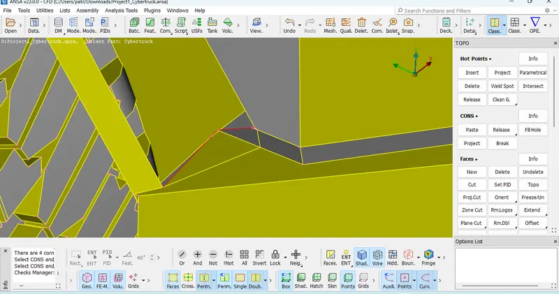
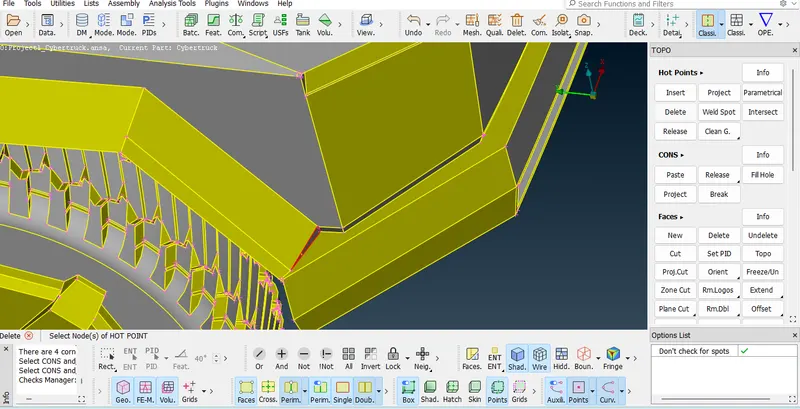
Here we can take note now the same intersection error shown front part, beacuse we delete the intersecting surface and create new surface on both side.
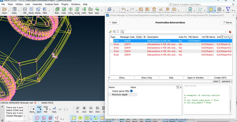
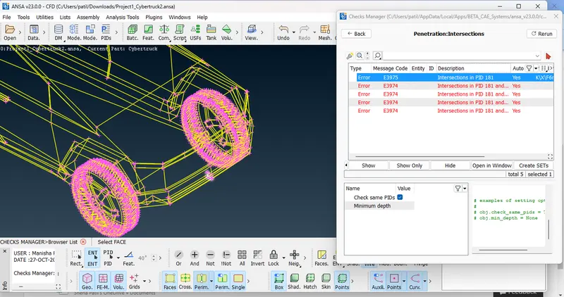
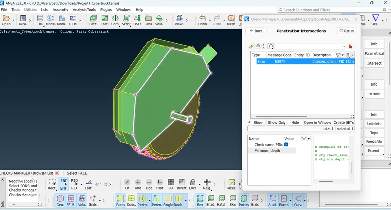
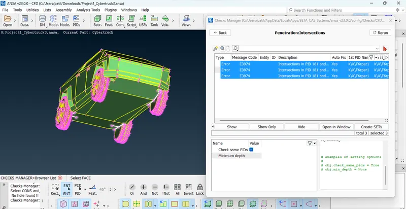
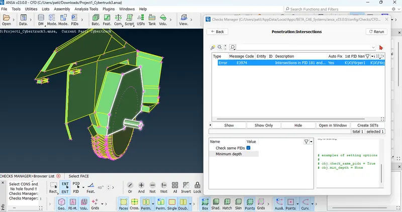
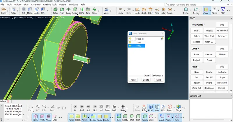
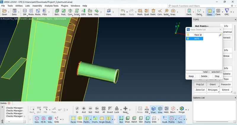
From the below snapshot we can say same intersection error appear with wheels, here shaft is intersecting with tyre guard.
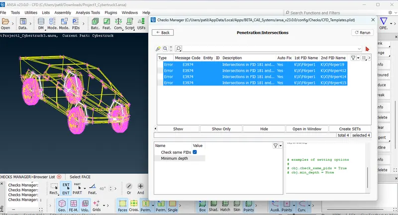
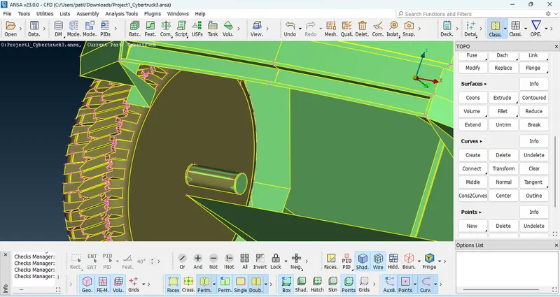
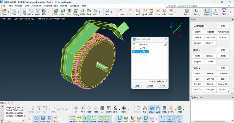
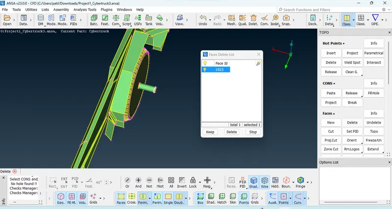
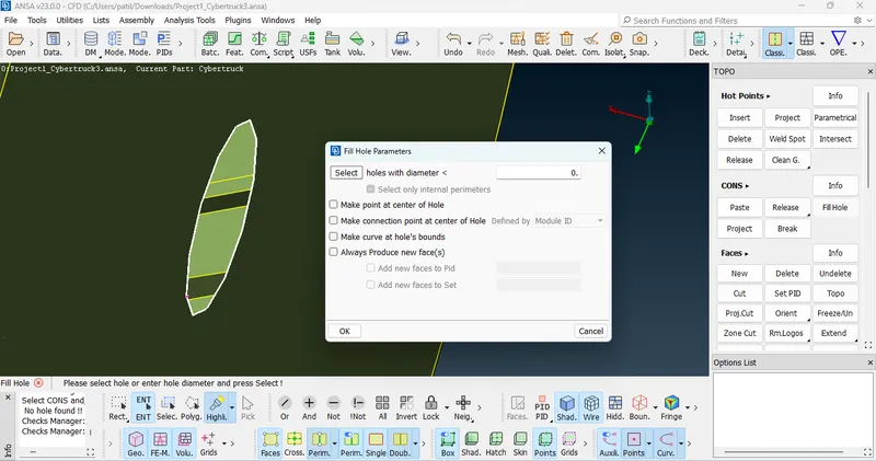
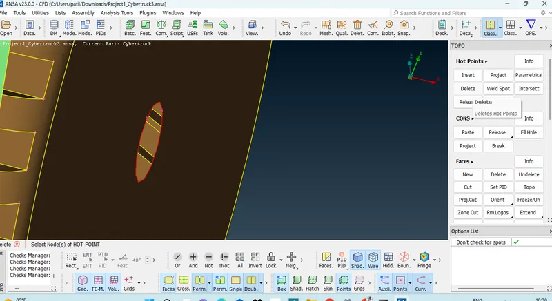
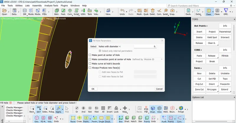
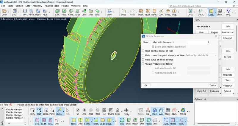
As we can see in PID mode shaft has two surface one of the surface intersecting to tyre guard, delete the surface before that isolate tyre guard using not tools. after deleted surface red coons appear, here we use fill holes to make surface. this is the same procedure for geometrical error for tyres.
PID Mode : In the PID Mode we get more idea about surface because of colour difference.
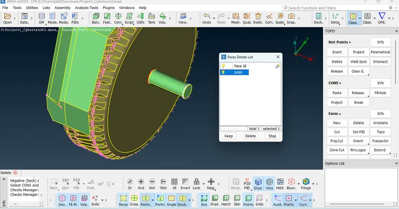
Fill Hole : create new surface in existing surface.
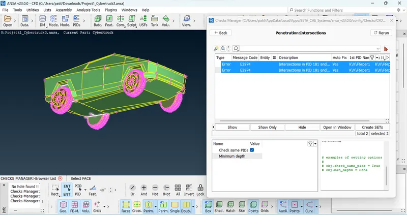
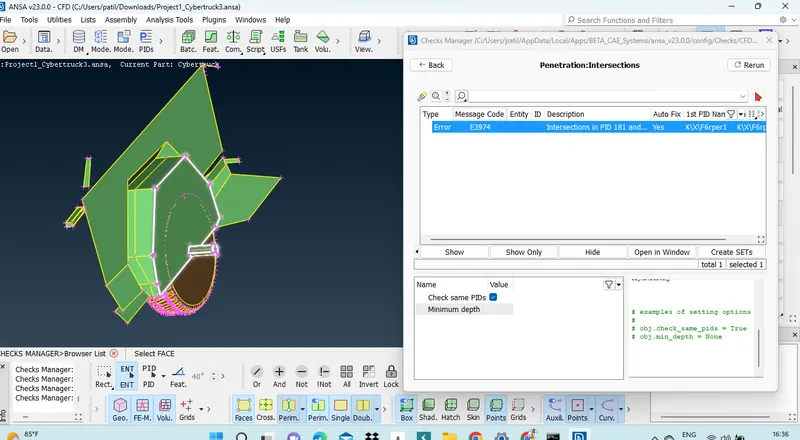
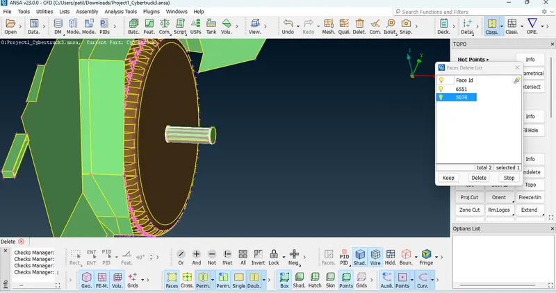
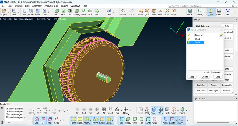
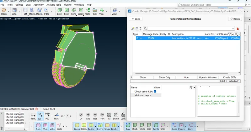
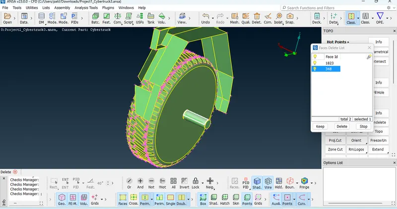
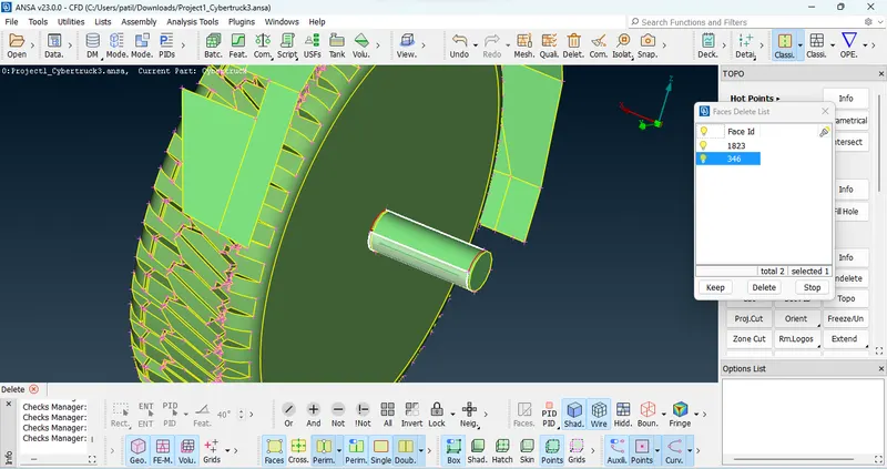
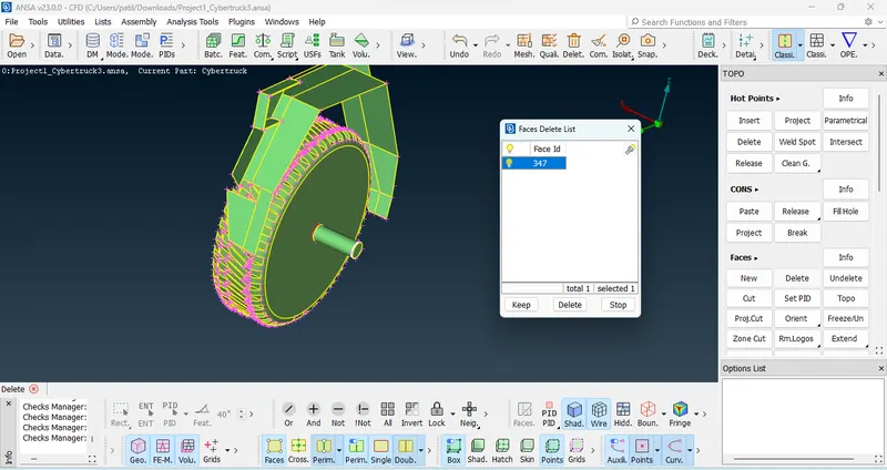
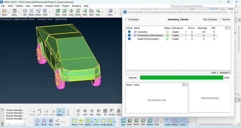
After clear Geometrical error and intersection error we can see result in fig.
Plane cut :plane cut option use for make half plane cut using three points.
Plane cut > Single Point > select points > Enter
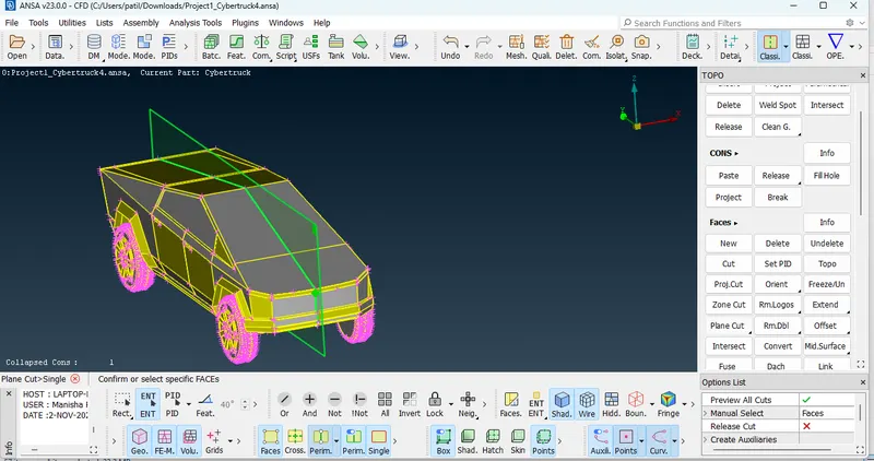
AFter creating cut delete half portion of geometry using Universal delete.
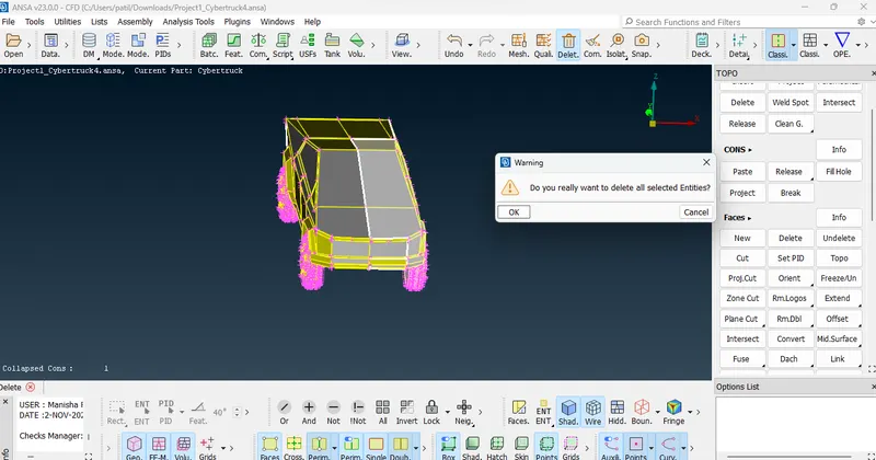
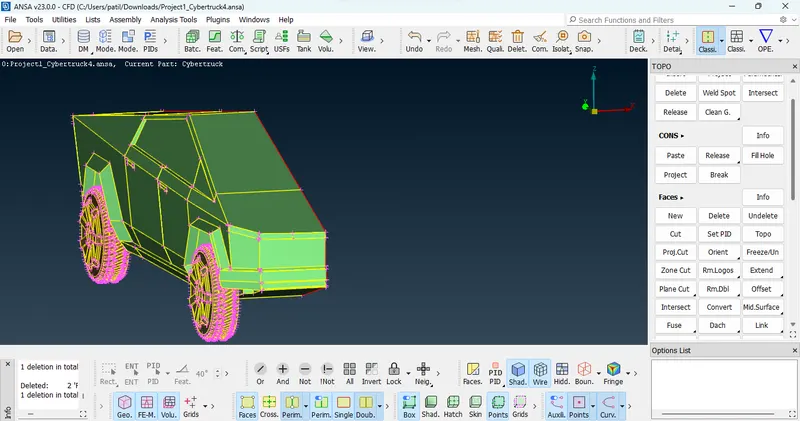
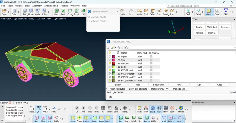
Assign PID for different parts of body using Set PID.
Set PID>New> Select Part > Middle click.
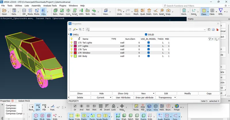
Here in Cyber truck we assign PID for Body, Window, Tail Lights,Head Lights, Wheels.
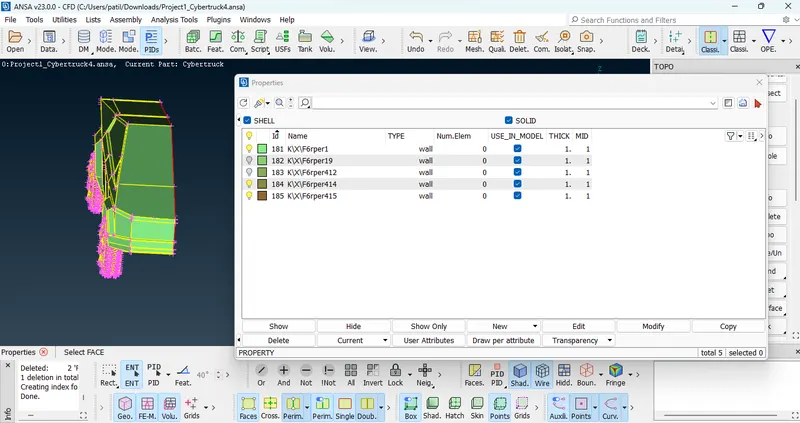
After assign PID Decompress the deck due to decompress all unassigned PID deleted,
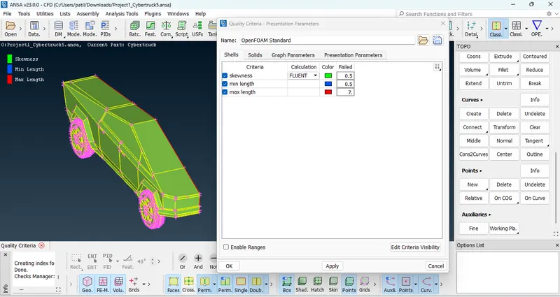
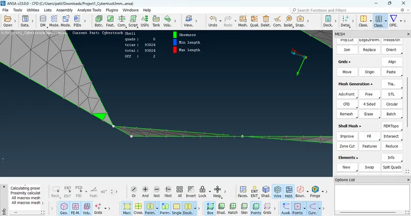
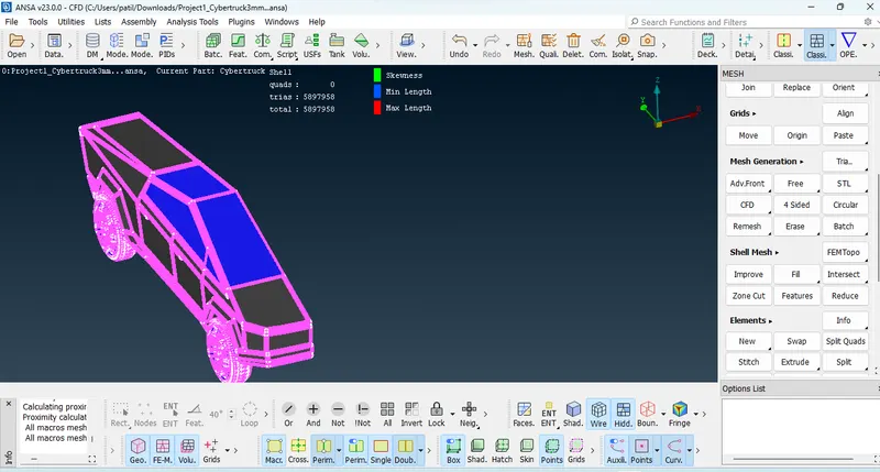
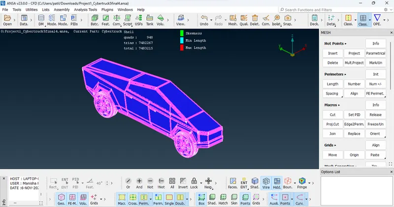
Meshing : Quality criteria should be defined before meshing, here we consider only min length, max length and skewness as shown in fig.
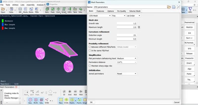
First we do meshing on window and Tyres of 2mm Mesh length, Here we are going to give mesh length in CFD Parameter.
Mesh Deck> Spacing> define Perimeters and Macrons> Apply CFD Visible.
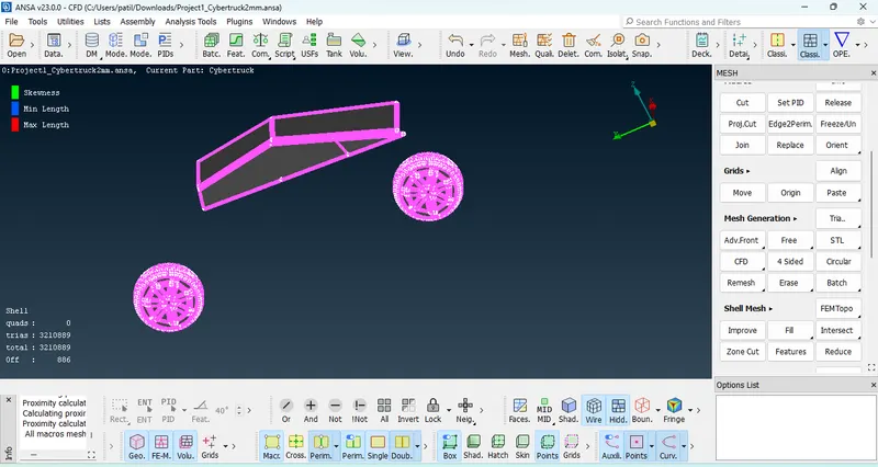
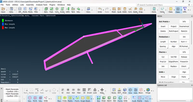
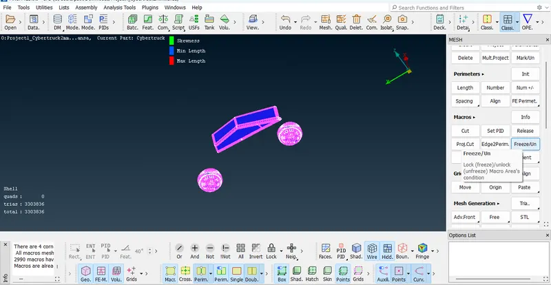
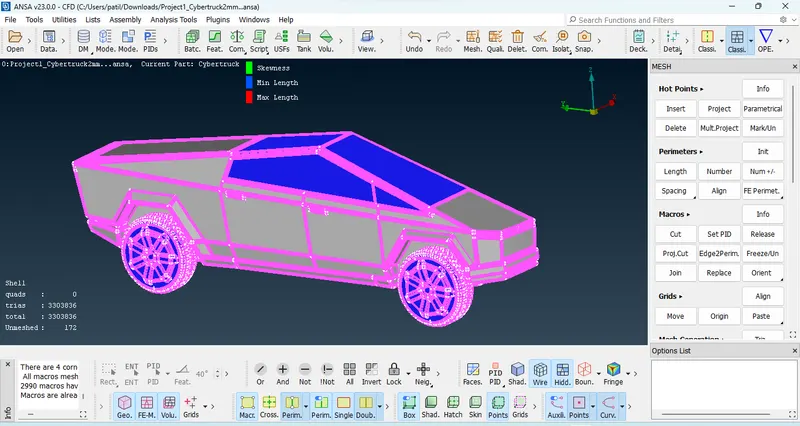
Body Meshing Length : 3mm
Max Length : 3.3 mm and Min Length : 2.3mm
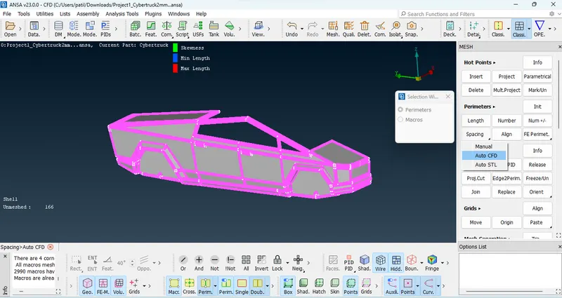
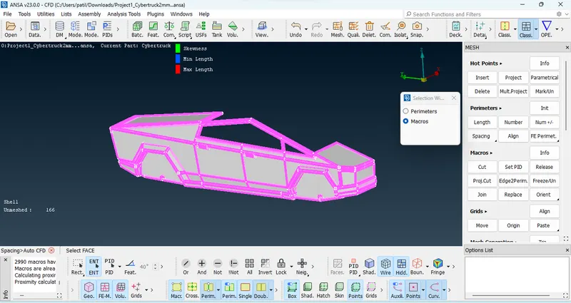
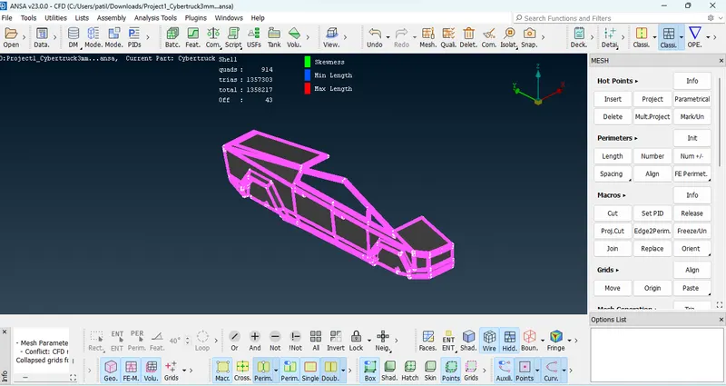
To reduce off element : Reshape and Reconstruct Geometry.
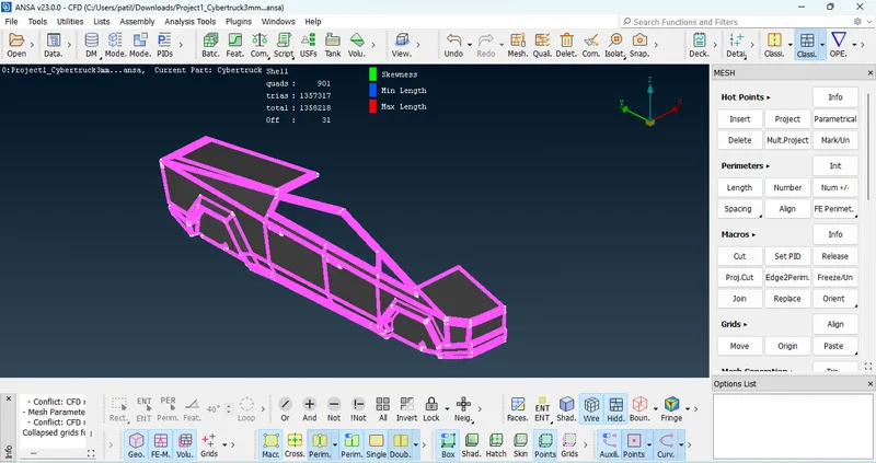
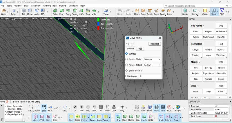
Element should be free from Skewness : Move grid size.
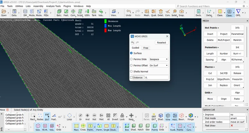
Lights : meshing length 4mm
min length : 3.5 mm and max length = 4.5 mm
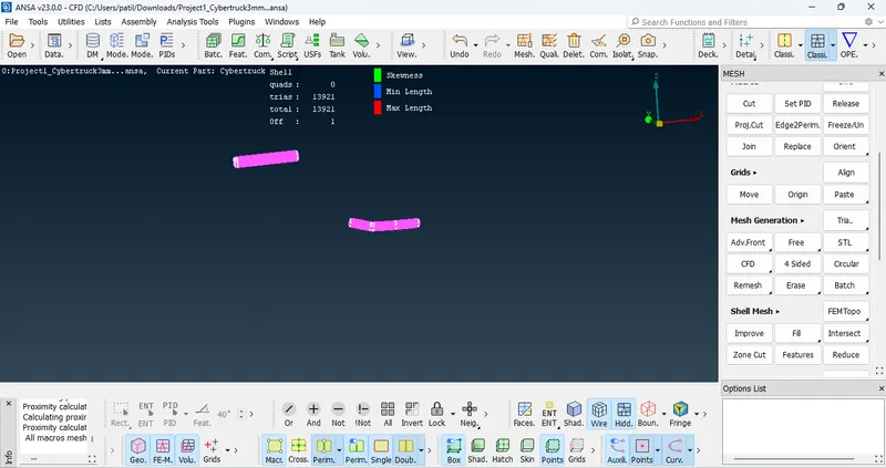
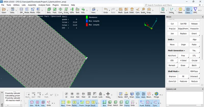
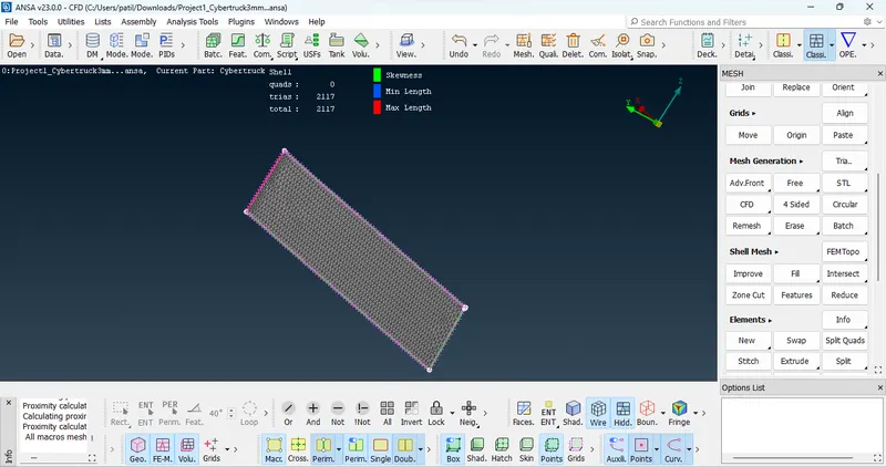
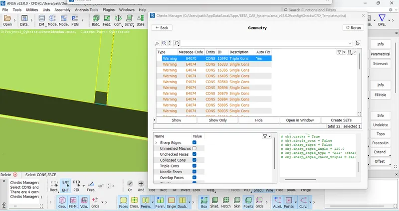
Geometry should free from red coons and triple coons. These single coons appear due to geometrical cut.
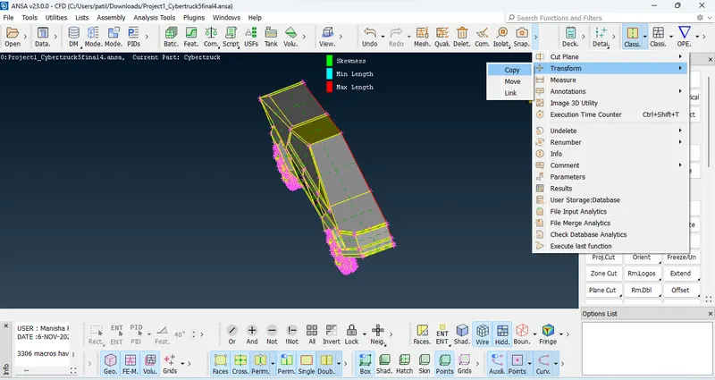
create symmterical part of geometry , go to transform,select the copy, create geometry using 3 nodes.
After complete geometry.
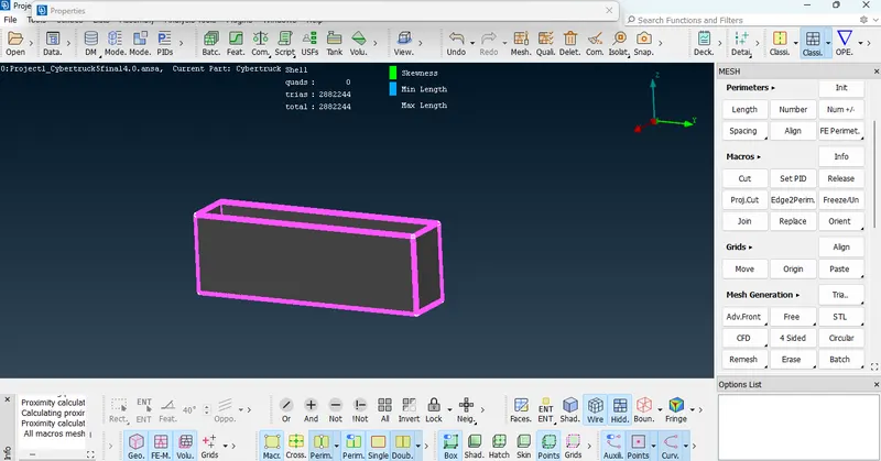
Wind Tunnel : creating Wind tunnel first we need to create Point, to creating point we should know total length of geometry.
First create mid point then take bottom point with respect to reference point.
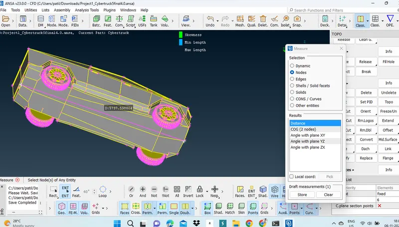
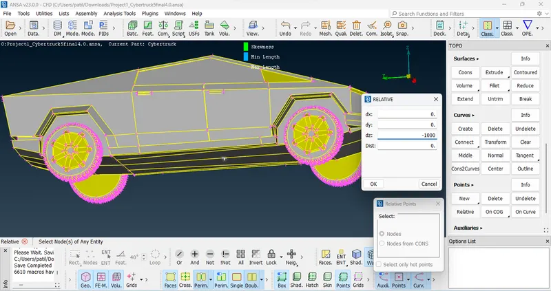
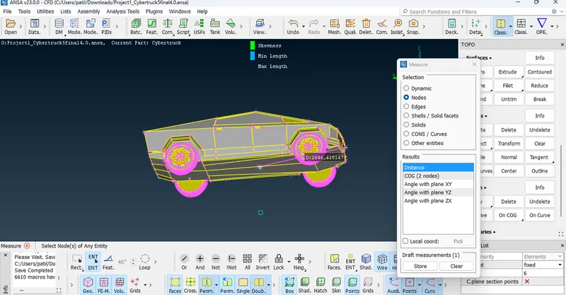
Standard dimension for wind tunnel :
Front distance = 4Xmm
Bottom Distance = 6Xmm
Top distance = 3Xmm
Side distance X mm
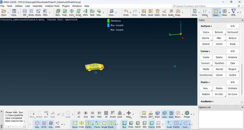
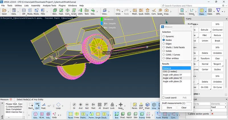
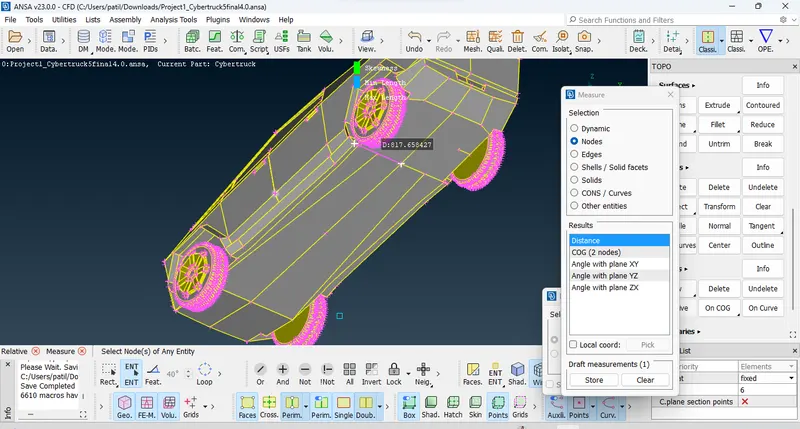
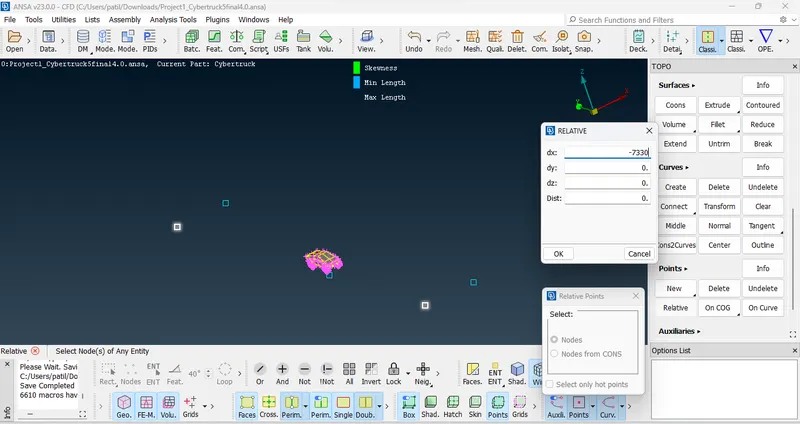
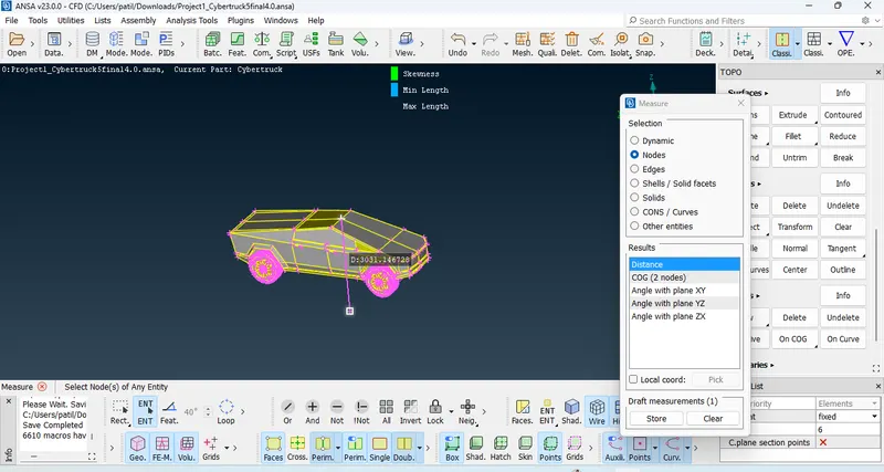
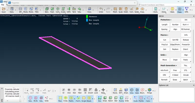
After creating all point and curves we create bottom face and top face and side face of wind tunnel.
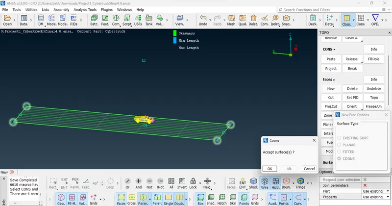
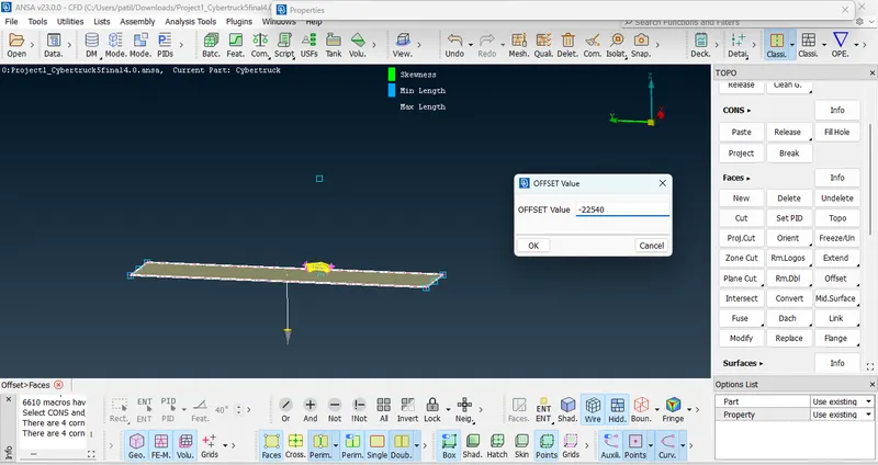
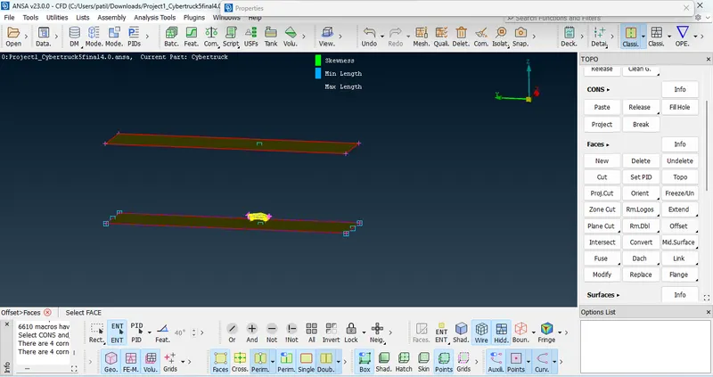
General meshing parameters for wind tunnel.
Min = 45mm and Max Length = 55 mm for all faces.
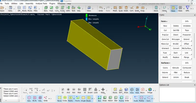
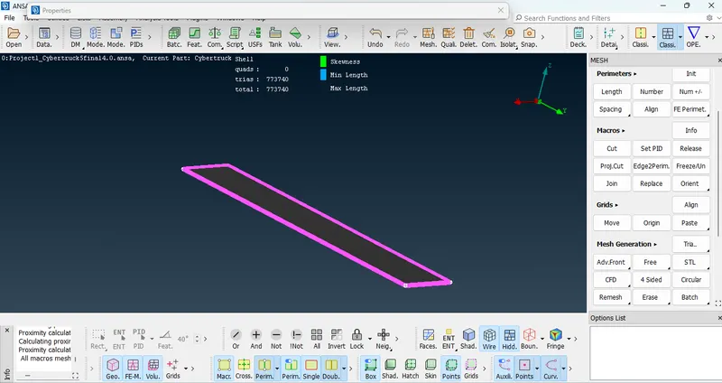
https://drive.google.com/file/d/1Unb1GjGZv7UKrashvu2tiVWs63Byp_vt/view?usp=share_link
Conclusion: Meshing is process to discretiaze the complex geometry into elements, this elemets discretize into small nodes to gives solver highly accurate solution for analysis. In this project done the meshing with tera elements with with different meshing length with quality criteria. qualty criteria improves the quality of mesh for better result. here we define meshing with three quality criteria min length, max length, and skewness. less skewness get more accurate result. overall get conclusion mesh should refine mainly at boundry conditon with define quality criteria.
Results : as we are doing preprocessing of geometry, it must be free from all errors like intersection and geometry error. Thereafter assign PID for cyber truck, meanwhile define quality criteria for meshing of truck,after done surface meshing we can see refine mesh on geometry. ensure before volume mesh all surface shoud be closed hence we created wind tunnel for volume mesh.