Project 1 : CFD Meshing for Tesla Cyber Truck
Aim:
- Check and solve all the geometries.
- Assign proper PIDs.
- Perform meshing with suitable target length and element quality.
Take away:
- One will be able to clean up the CAD using different tools.
- Assign PIDs.
- Mesh with appropriate mesh length.
==============================================================================
Pre-Geometry clean up:
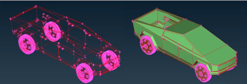
- As seen in the above figure, there are lot of single cons present in the geometry. One must avoid it.
- Initially, run a topo check. (TOPO DECK >> FACES >> TOPO).
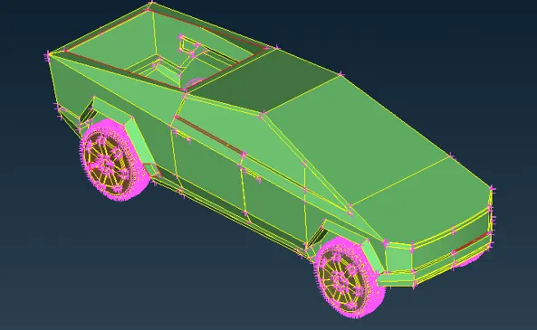
- Since there are not much errors to resolve, we will still solve it individually.
==============================================================================
Body clean up:
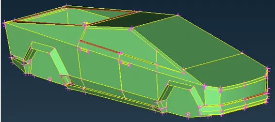
>> Exploring NEW option:
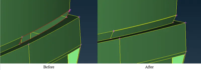
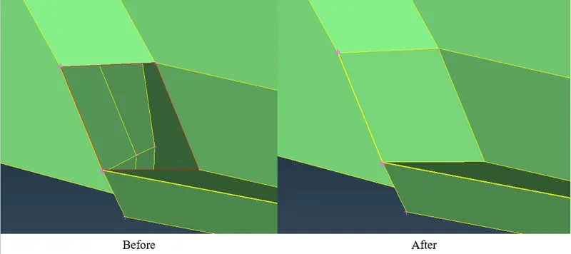
- This tool creates a surface or face where there is no face or surface.
- Select NEW option. (TOPO >> FACES >> NEW).
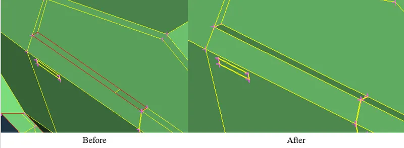
- Other place where we can use NEW option.
- Run check manager.
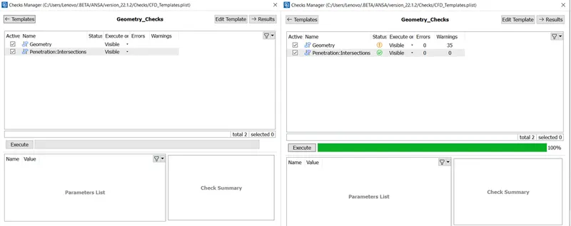
- Cross indicates an error and a tick indicates no error.
- Remaining errors.
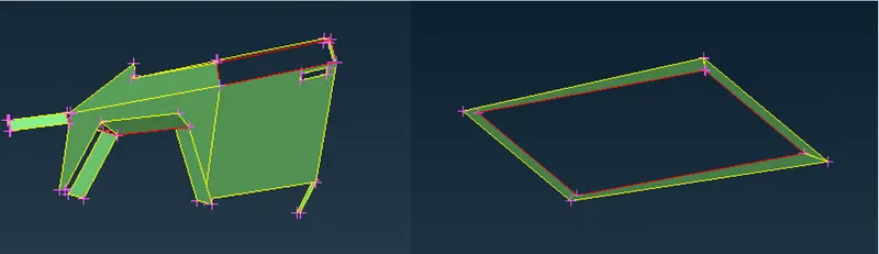
- There is intersecting surfaces.
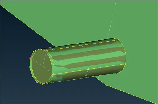
- This can be cleaned using UNIVERSAL DELETE option present in the ribbon.
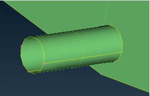
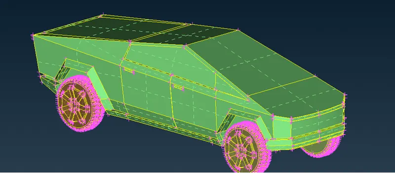
- At this stage, there are no single cons.
==============================================================================
Assigning PIDs:
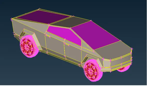
- Assigning PIDs to the component makes it easy bifercate and visualize them.
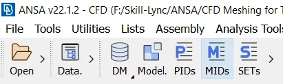
- Open PID dialogue box present in ribbon.
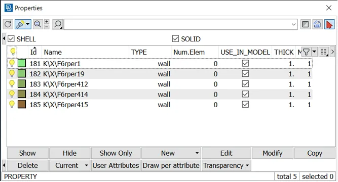
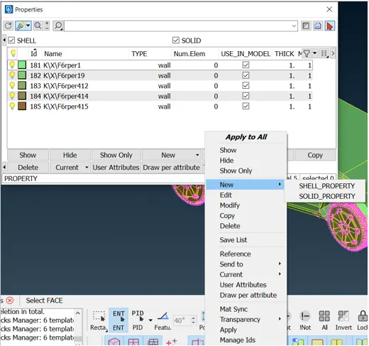
- Right click in the open space.
- Select NEW and then select SHELL PROPERTY.
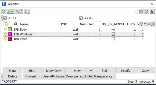
- Assign the PIDs as follows:
==============================================================================
Meshing:
Body = 3 mm.
Windows = 2 mm.
Tyres = 2 mm.
>> Meshing Tyres:
- In order to assign quality criteria one must know the minimum and maximum length present in the geometry.
- Measure it using the measure tool.
- Target Lenght = 5 mm.
- Maximum Lenght = 6 mm.
- Minimum Lenght = 2 mm.
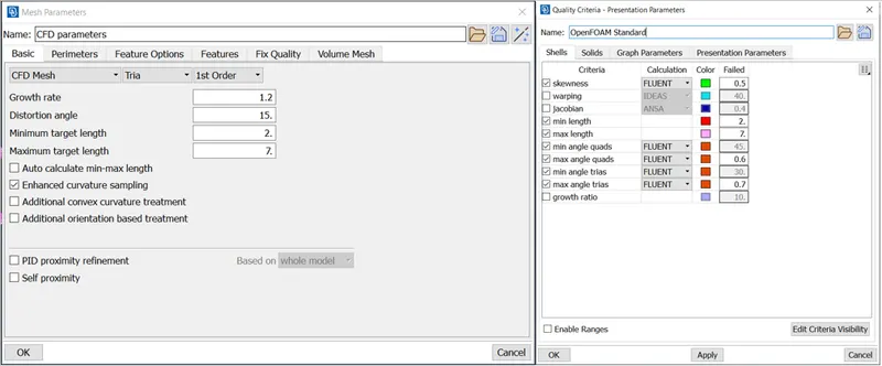
- Select LENGHT option. (MESH DECK >> PERIMETERS >> LENGTH).
- After specifying the length, select SPOT MESH option. (MESH DECK >> MESH GENERATION >> SPOT MESH).
- The Mesh:
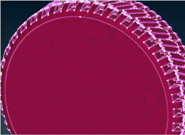
- Off elements:
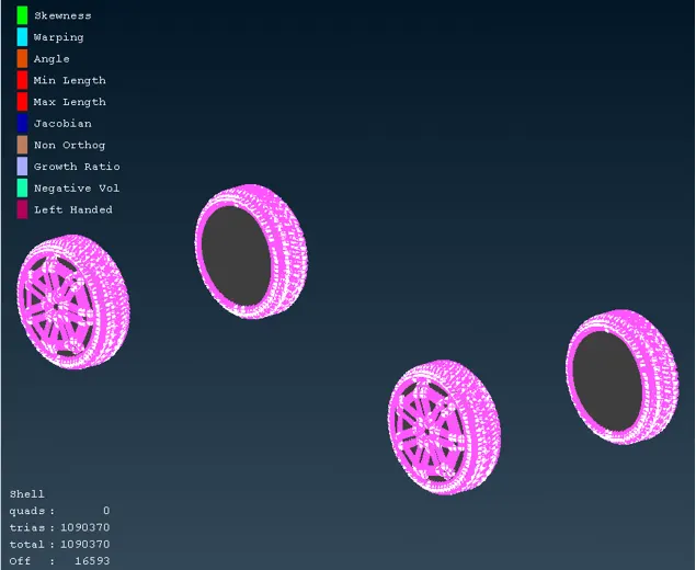
- To remove off elements, try using RECONSTRUCT option. (MESH DECK >> SHELL MESH >> RECONSTRUCT).
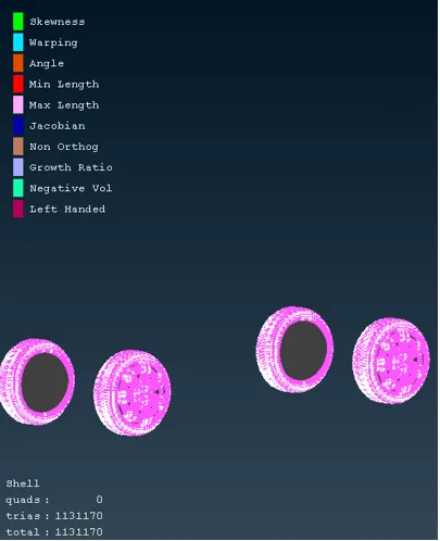
- No more off elements!
>> Meshing Windows:
- In order to assign quality criteria one must know the minimum and maximum length present in the geometry.
- Measure it using the measure tool.
- Target Lenght = 5 mm.
- Maximum Lenght = 6 mm.
- Minimum Lenght = 3 mm.
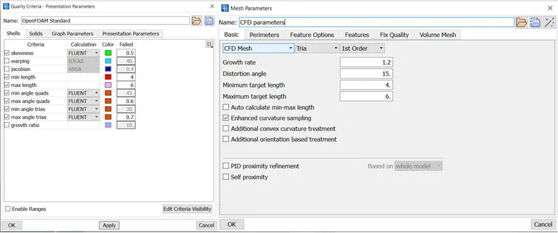
**Correction: minimum lenght = 3 mm.
- Select LENGHT option. (MESH DECK >> PERIMETERS >> LENGTH).
- After specifying the length, select SPOT MESH option. (MESH DECK >> MESH GENERATION >> SPOT MESH).
- The Mesh:
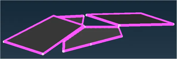
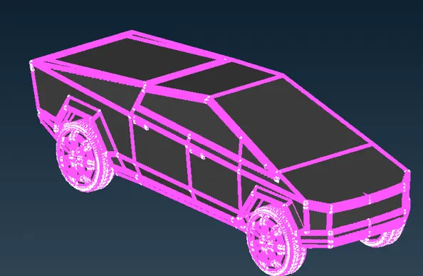
>> Meshing Body:
- Before meshing, remove all the unecessary cons that might affect the mesh quality.
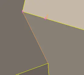
- Remove some more if present.
==============================================================================
Creating Wind Tunnel:
- Create the first point as reference to make sure that ground is lower than the tyre.
- To create a point below tyre surface, select RELATIVE option. (TOPO DECK >> POINTS >> RELATIVE).
- Give a distance of 500 mm in negative Z direction.
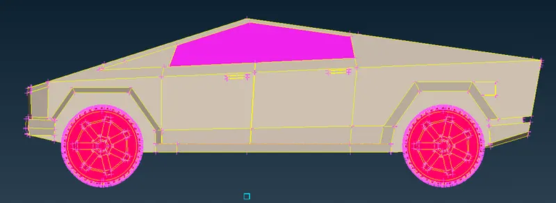
- Distance from front of the car to rear of the car = x = 5746 mm.
- Distance from front face of the car to the inlet of the wind tunnel = 2614 + 4x = 25602 mm.
- Distance from rear face of the car to the outlet of the wind tunnel = 3310 + 6x = 37792 mm.
- Side walls of the wind tunnel are 3 time the width of the car = 3*1880 = 5640 mm.
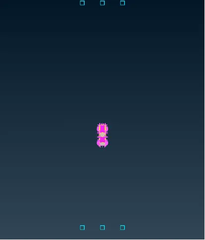
- Top view of points created.
- Using this points one can create surface/face.
- First create curves and then using those curves create surface/face.
- Select CREATE option. (TOPO DECK >> CURVES >> CREATE).
- Now, create top surface of the wind tunnel.
- Top surface = 2301 + 3x = 19542 mm.
- To create top surface, select OFFSET option. (TOPO DECK >> FACES >> OFFSET).
- Select bottom surface as reference.
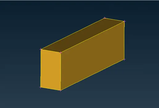
- Wind Tunnel is ready.
- Assign respective PID.
==============================================================================
Meshing Wind Tunnel:
- Bottom Wall = 100 mm.
- Top Wall = 200 mm.
- For side, inlet and outlet, we will be using variable meshing along the verticla length.
- Select SPACING option. (MESH DECK >> PERIMETERS >> SPACING).
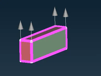
- Final mesh is shown below:
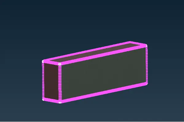
- Volumetric Mesh is not done due to limited CPU performance.
==============================================================================
Conclusion:
- Was able to clean up the geometry using different tools.
- Assigned respective PIDs.
- Performed part wise meshing.
- Creation of wind tunnel and its meshing.
Module Link:
https://drive.google.com/file/d/1uzHss2mFUbp-42Nv4lCTarAxrMA94wTI/view?usp=share_link