Week 3 Challenge : CFD meshing on Turbocharger
Aim:
- To create a CFD mesh on Turbo charger by using Ansa.
Objectives:
- Set target length and mesh the model.
- Blade stage-1 = 1 mm
- Blade stage-2 = 1 mm
- Impeller = 2 mm
- Shaft rotor = 1 mm
- Turbo casing = 5 mm
- Compressor casing = 5 mm
- Inlet casing cover = 5 mm
Procedure:
Open an ANSA software and import a Geometry.
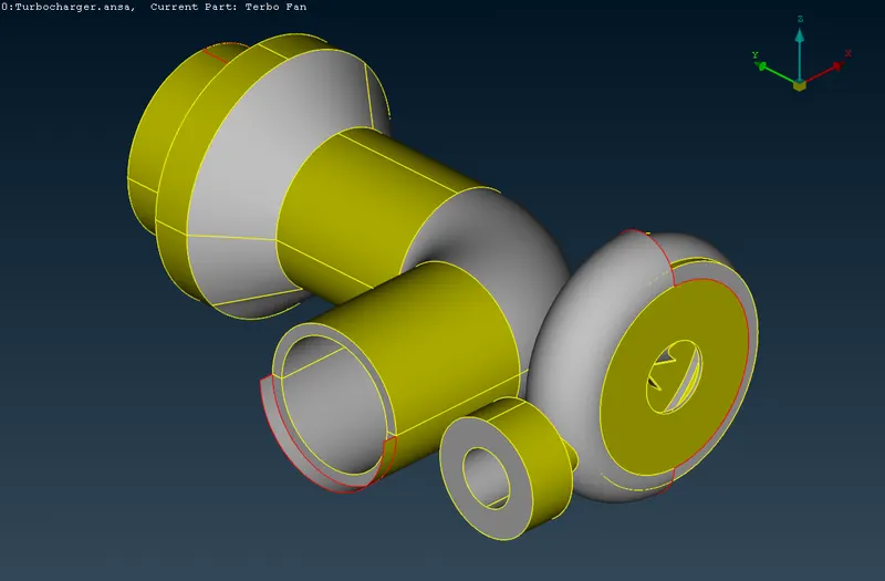
Fig: Imported Geometry
After Importing geometry, Check the geometry and its shows some error in topology.
- Checks>Geometry
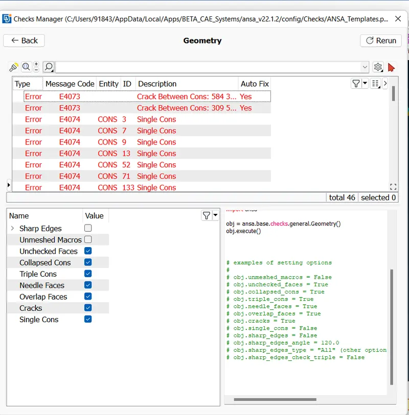
Fig:Geometry check
Now Started the topo cleanup and create a single cons into Double cons.
- Faces> New
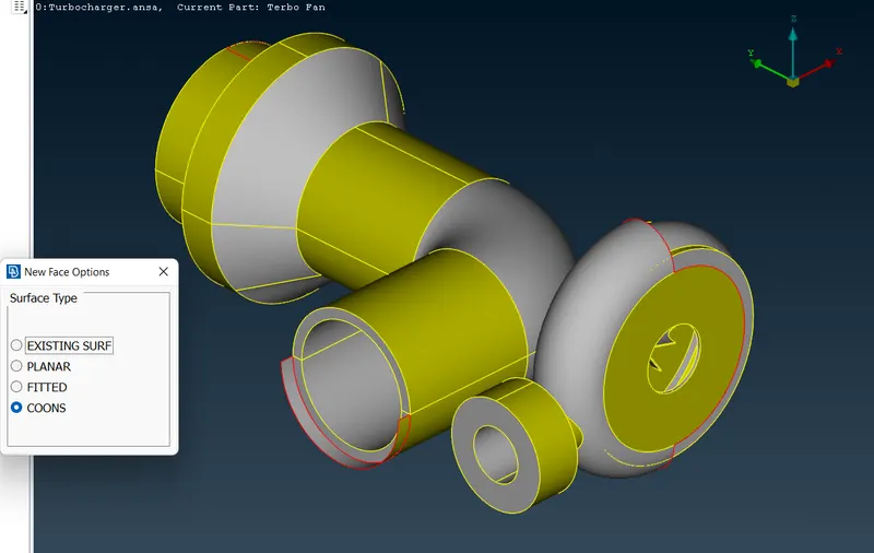
Fig: Create a new surface
- Cons>fillholes (fill the small holes in the surfce)
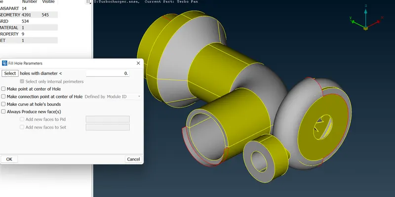
Fig:Fillholes
Make that rotor shaft as a single body throughout the impeller.
Now Topo cleaning was done and check the entire body was closed.
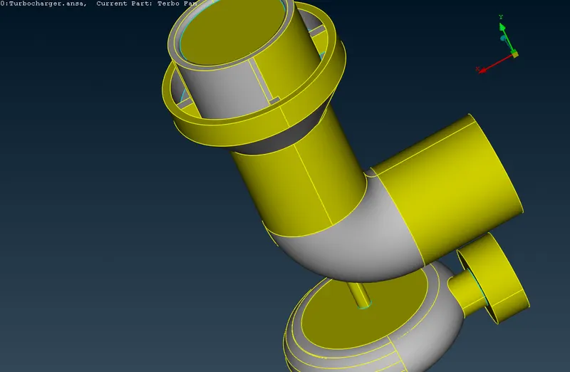
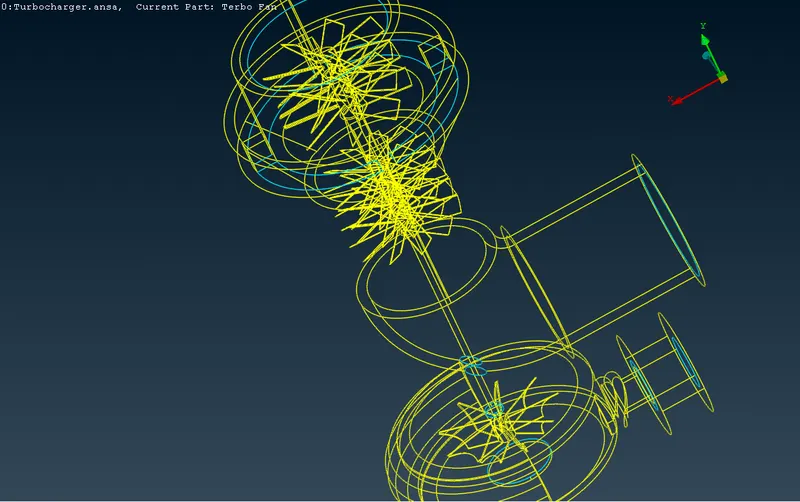
Fig:Final Geometry
Before entering to the mesh hide the cut planes which is very nearer or else surface is less then 5mm.
Now create a properties gives names of these body.
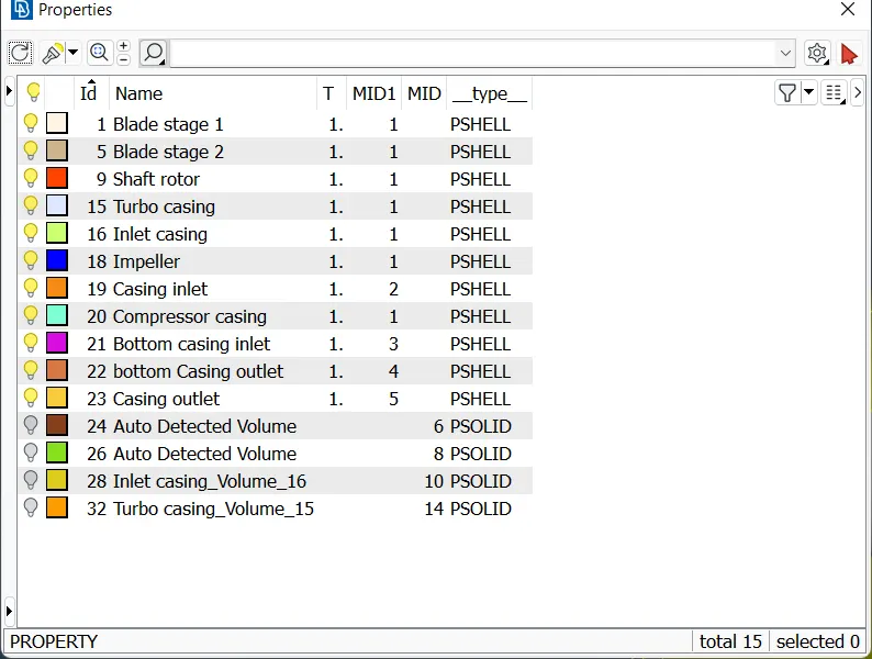
Fig: Properties
Now TOPO was completed next move to Mesh.
Select length option and gives the values of perimeter and macros
- Perimeters>Length
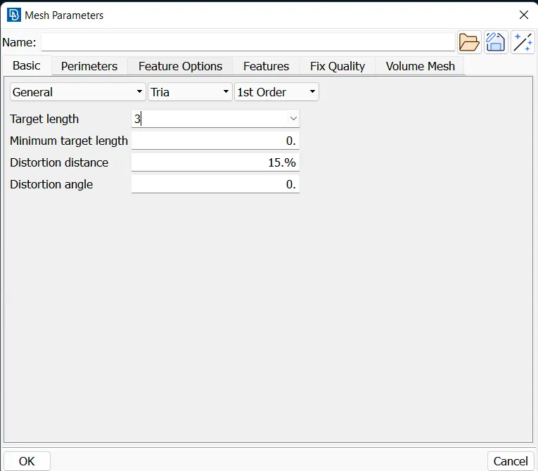
Fig:Length for Mesh
Now, select the spot mesh and create a Mesh
- Mesh Generation>spot mesh
Next move into volumatric mesh and get into volume> define. After that delete the unwanted volume detected by ansa.
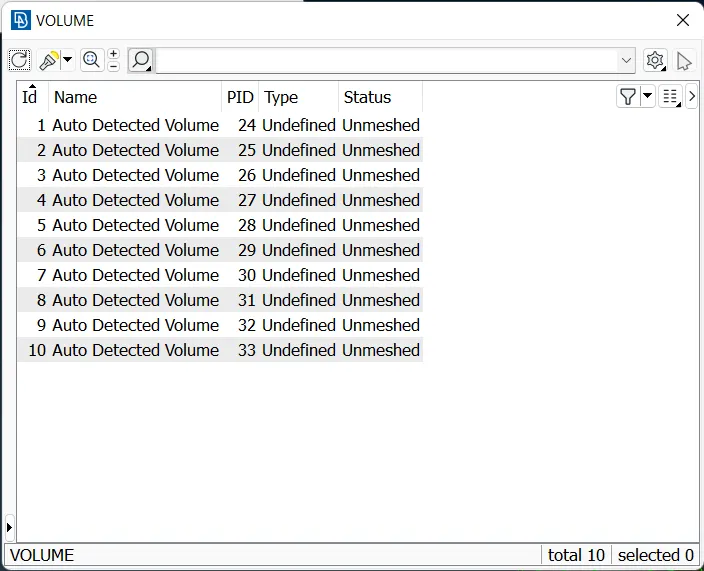
Fig: Volume properties
Now select Tetra CFD and create a volumetric Mesh.
Results:
Surface Mesh
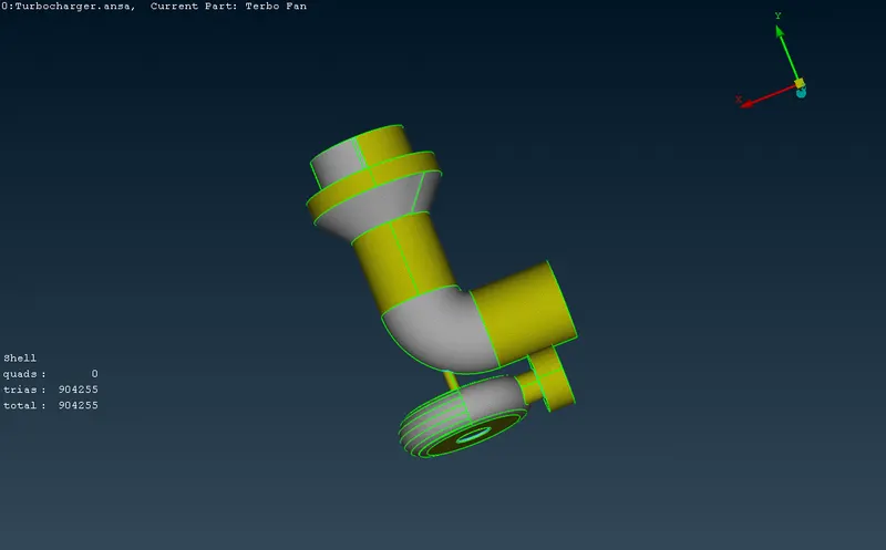
Surface mesh of 1mm Blades and rotor shaft
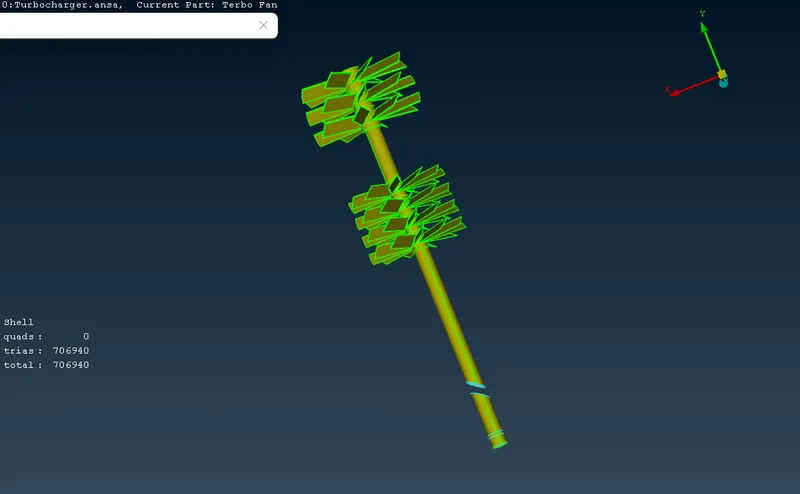
Surface Mesh of 2mm impeller
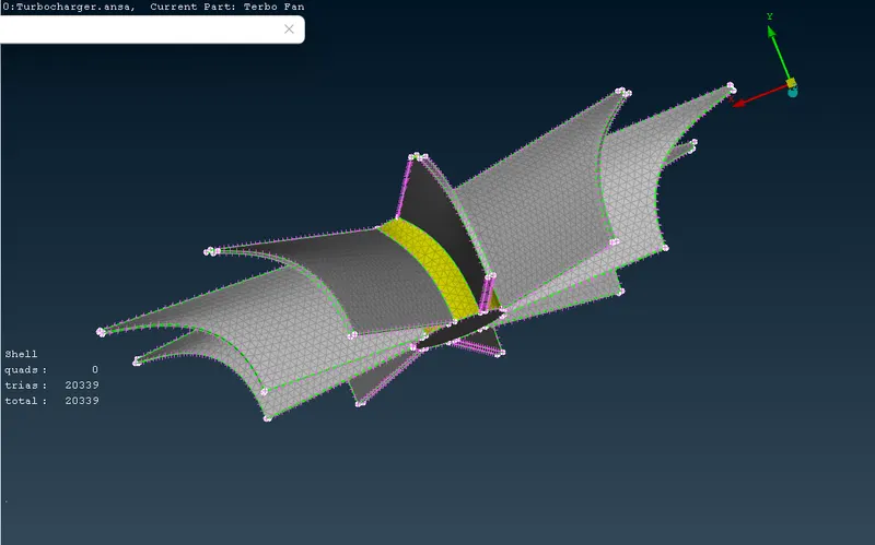
volume mesh
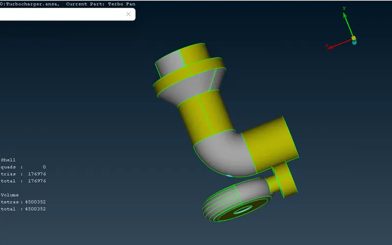
cut the volume mesh (tetra cfd mesh)
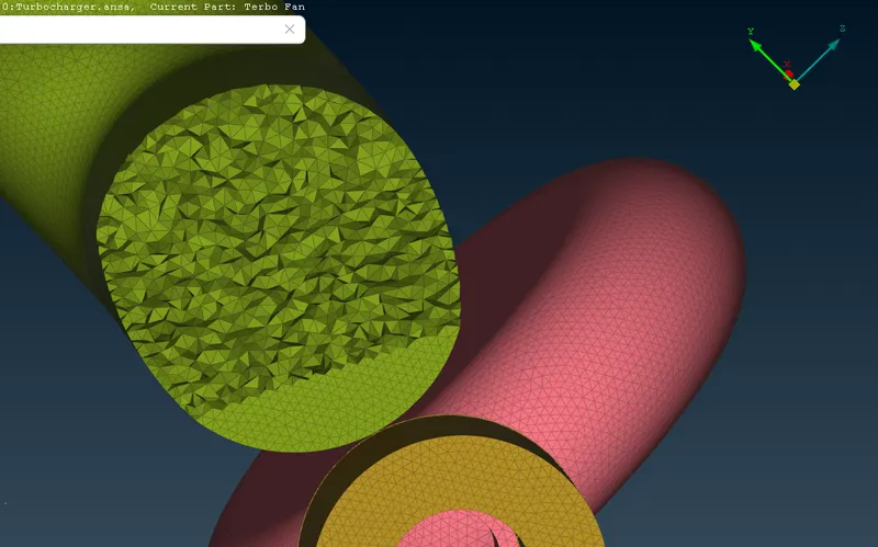
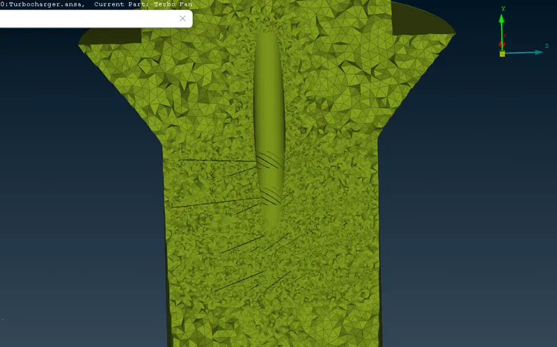
cut by the cross section of plane
Conclusion:
- Creating a CFD meshing on Turbocharger by using Ansa is done.
- For getting a fine mesh, to decrease the node length.
- Volume metric mesh create a Tetra CFD mesh is done.