Project 1 : CFD Meshing for Tesla Cyber Truck
OBJECTIVE- For the given Tesla Cybertruck model , check and solve all geometrical errors and Assign appropriate PIDs. Perform meshing with the suitable Target length and element Quality criteria.
Steps involved:-
- TOPOCLEANUP
- PID's Assign
- 2D meshing with different mesh length for different PIDs
- Wind Tunnel creation
- Volumetric meshing
Solution procedure :
- For solving we follow the below procedure ,
- Import the CAD model.
- Identifying & cleanup of the topological / geometry errors .
- Geometry check-up.
- Setting-up of relevant PIDs.
- Defining the element size or length.
- Setting the mesh parameters , selection of meshing type and generating surface mesh of the CAD model .
- Resolving the errors in the surface mesh.
- Creating the wind tunnel for external flow CFD analysis and surface mesh of wind tunnel.
- Generating volumetric mesh.
1) Importing CAD the model :
- To import the CAD model we follow below steps,
Go to file -> open -> browse the location of the CAD model -> select it click on open.
Original Geometry:-
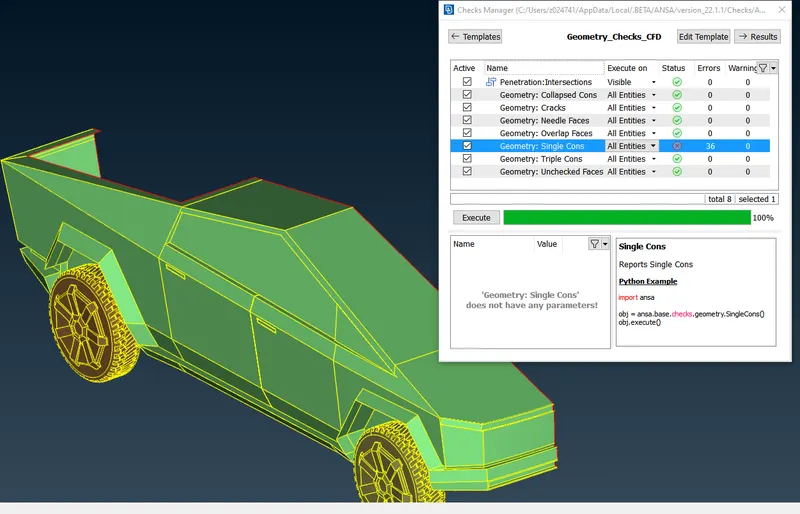
This is our raw geometry when we activated single cons we can see whole geometry covered in single cons, To avoid single cons do topo for whole geometry this will solve issue of single cons.
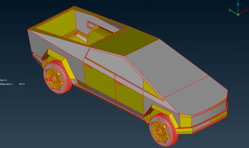
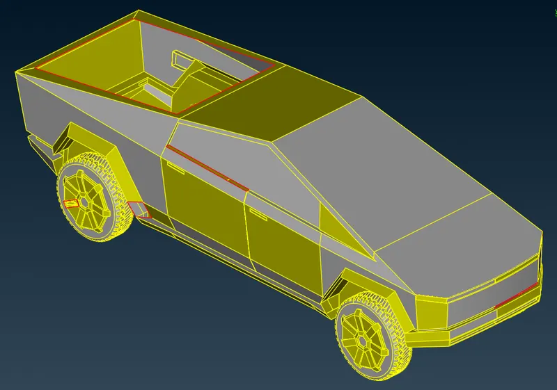
Geometry after applying TOPO tool
All single cons are converetd to double cons.
Step 1 - TOPO cleanup
- Create cut on geometry so that geometry could be divided in half
- Delete half geometry, Always delete the side where you see less work had to be done in order to fix geometry.
- Patch open surfaces
- Delete overlapping and extra surfaces
- convert triple cons to double cons
Divding Geometry after creating cuts in middle
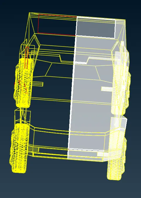
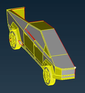
Creating new surface to patch holes and clear single cons-
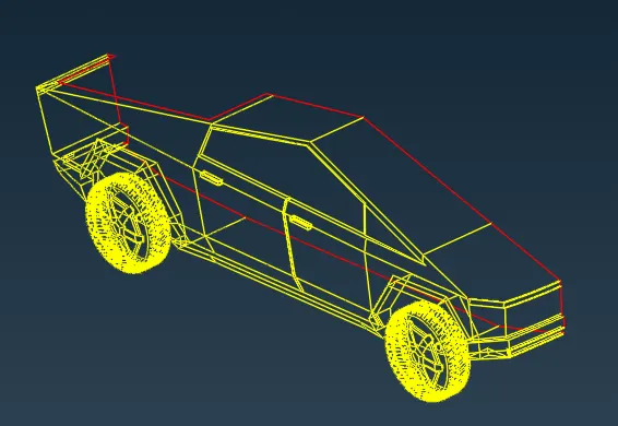
Geometry check after Topo cleanup
By doing we check there are no unnescessary single cons present and we are good to go for symmetry
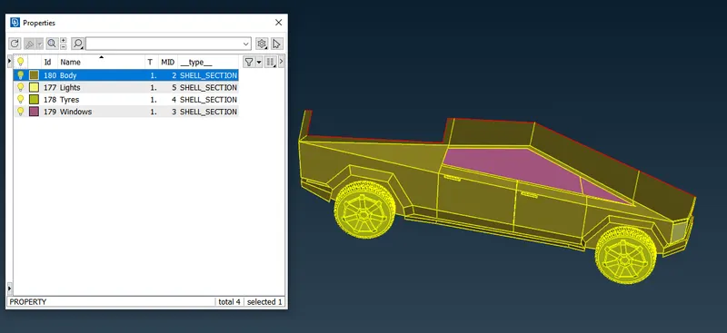
Step-2 : Setting-up of relevant PIDs :
- In this step we assign the PID for different parts and give a name and colour to differentiate between the components and ease up the working on the components individually.This is also done to specify names to different boundary conditions for various parts.We need to activate cross hatches before setting-up PIDs.
- If you open properties manager at the top , you will have some default PID's which are assigned. We have to create new PID's to assign for our components. Inorder to create new PID , right click on properties manager -> click new -> then select pshell -> then again select pshell -> then give name in the popup box -> then ok .You can change the colour by double clicking on the colour box -> then ok .
- In the similar way create PID for all the components.
- Let us also add transperancy for windows to be more realistic in the colour box .
- Then next thing is assign these PID's to the components of the geometry .
- To apply , we select /click on the PID to apply in the PID manager -> then right click on it -> then click on apply -> then in the geometry select the cross hatch of the surface you want to assign -> then middle click . In the similar way we have to apply PID's we have created . To give the PID we select with the different type of selection available to select the exact surface needed.
- Then after assigning the PID , delete the empty orginal PID's which has no components assigned by using compress .
- In the below image you can see that list of PID's that we have assigned.
STEP 3 : SURFACE(2D) MESHING
- Here we perform all the three tasks ,defining the element size or length and setting the mesh parameters, selection of meshing type and generating surface mesh of the CAD model and resolving the errors in the surface mesh by selecting each PID one by one and perform above tasks .
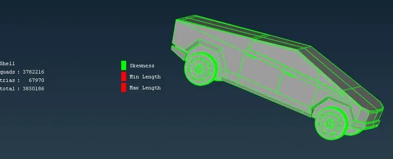
- Before meshing we have to give quality criteria .Here we select openFoam solver deck,so that we get the quality criteria of that solver .
- Here as we have different surfaces , we will use different quality criteria for different surfaces , we will change mesh length as per our surface complexity and surface size . If surface is small we have to use smallest target length , if larger we use accordingly .We set the element lengths accordingly, as a fine mesh for every element would be time consuming & will be computationally Expensive.
- We start meshing from smallest component to larger component one by one .
- We mesh the body PID last because as it is attached to lot of other PID's if you mesh it first and mesh other PID attached to it later it may lead to erase of mesh of body at that location .For this reason we mesh the body PID last .
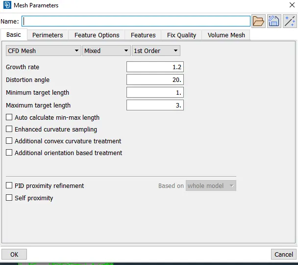
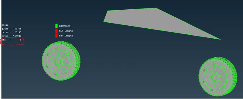
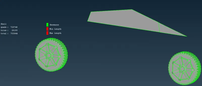
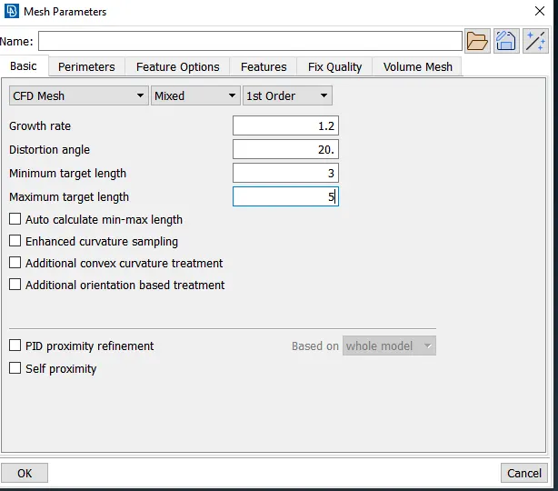
- We isolate each component/PID and give above quality criteria(target, min and max length ,skewess etc. ) in quaity criteria and then in mesh parameters .We also select skewness and give value as 0.5 for all the PID's and also min length 0.2 mm & max length 6mm .
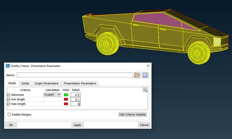
Mesh length for differnt PID's
Body- 3mm
Lights - 4mm
Rim and Tyres - 2mm
Windows -2 mm
Surface Meshing of Tyres and Windows:
Surface Meshing of Lights:
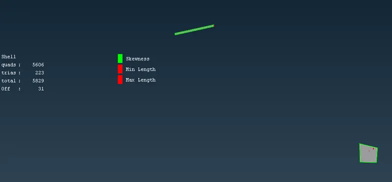
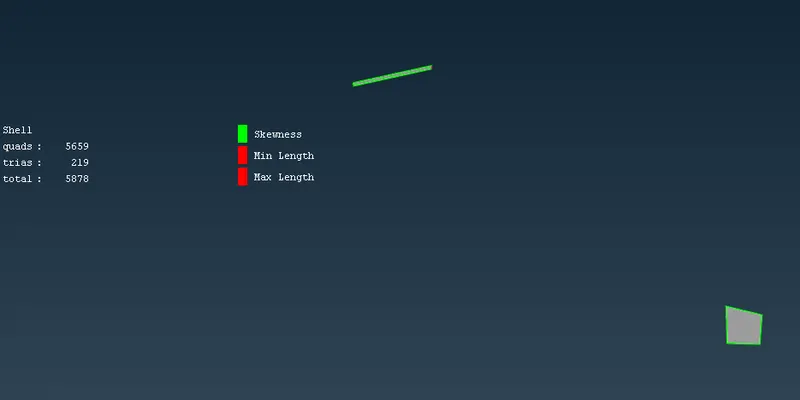
Surface Meshing of Body:
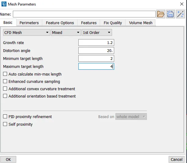
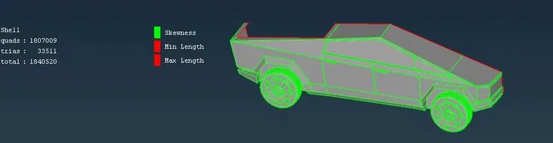
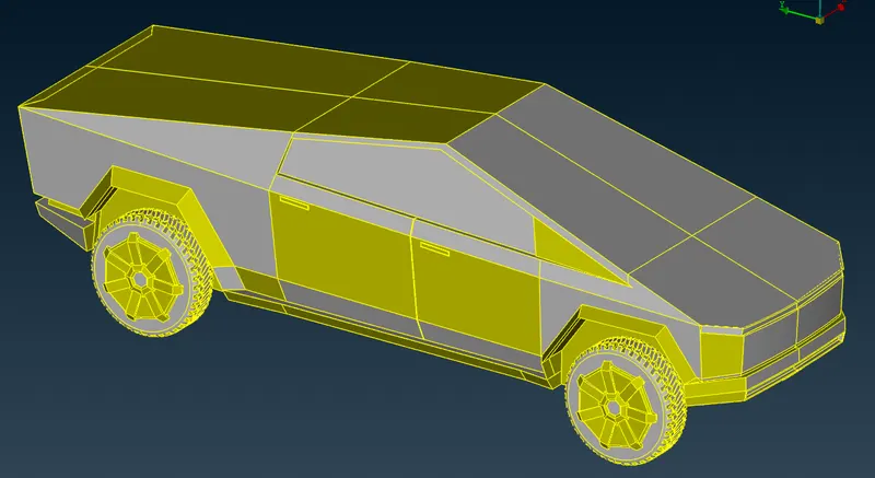
STEP-4 : CREATING SYMMETRY
- Go to transform tool and choose copy, a dialogue boz will appear , choose entity and drag your mouse doing right click to select whole geometry and do right click.
- In the new dialogue box which appears choose symmetry and three points plane
- Choose any three points to automatically fill required coordinates.
- Click on apply and then click ok in the new dialogue box which appears . Don't make any changes.
- Check for single cons as this common error after doing symmetry and solve them by using patch tool or by creating new surface.
STEP - 5: CREATION OF WIND TUNNEL
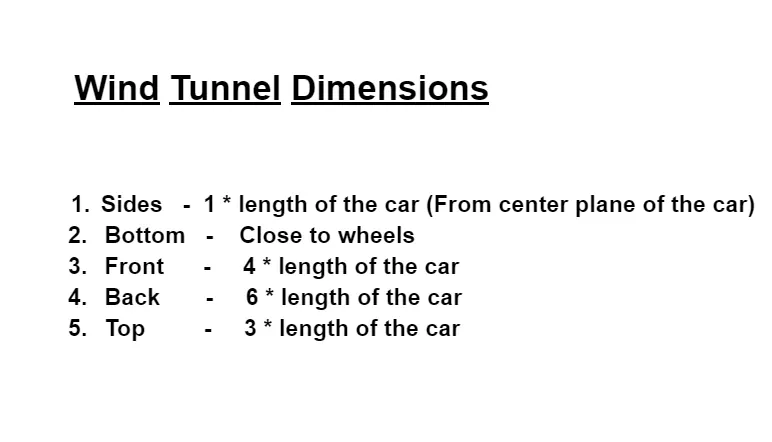
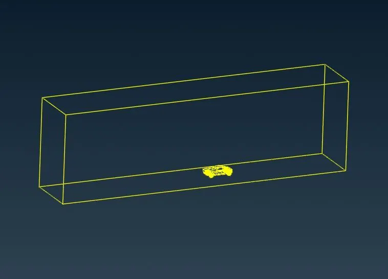
- Inorder to create a Wind tunnel, first create a point by selecting relative at 650mm from body to bottom by selecting a hot point at a distance of 650 mm to bottom .
- By taking that point as reference , we create anotheer point to front of car at a distance of 4* 5700 = 22800 mm ( 5700 mm is length of car ).
- Then we create another point at the back at a distance of 5700 +6* 5700 = 39900 mm (5700 mm is length of car and as we create relative to front point we add 5700 mm more).
- Then we create another two points on both sides of car , with the help of front and back of car , which we have created , such that we can join all the four points with the help of curve and create a surface there with the help of 4 curves .This completes creation of bottom part .
- Then we create top face by using offset at a distance of 1900 + 3* 5700 = 19000 mm (1900 mm is distance from bottom to top of car and 5700 mm is length of car ).
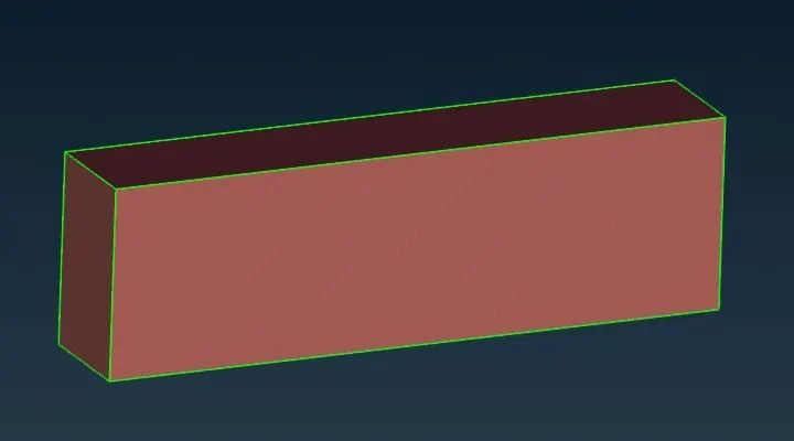
- Now using these two surfaces we create new surfaces on all sides and close the volume , such that it forms a wind tunnel .
- Now we create and assign PID's for the wind tunnel walls.In the below image we can see that PID's are created and assigned.
STEP - 6: SURFACE MESH OF WIND TUNNEL
- Now that the wind tunnel has been modelled, it has to be surface meshed first, such that the mesh size gradually grows from top to bottom.
- If we have refined mesh length at the top ,then we will have lot of cells and lot of computational effort is required to solve .So , we give varying mesh length .
- This can be done by using the spacing option under perimeters in mesh utility menu.
- choose geometry biasing option & set the dmin value as 20 and dimit value as 100 and factor as 1.2 and select all the four vertical perimeters.But before that we surface the top part by giving a length of 100 mm and bottom part with a length of 20 mm .
- Then generate surface mesh. In the below image we can see that the mesh length is varying and increasing from bottom to top.
Learning outcome:
In this process of working on this project we have learned how to,
- Identifying & cleanup of the topological / geometry errors .
- Geometry check-up and setting-up of relevant PID's and defining the element size or length .
- Setting the mesh parameters and quality criteria, selection of meshing type and generating surface mesh of the CAD model .
- Use Quality criteria tool & also learnt various options under the shell parameters such as Skewness, min length, max length , max angle &min angle, etc.
- Resolving the errors such as skewness, min & max lengths using various tools.
- Set-up Wind Tunnel as per given dimensions for external flow CFD analysis and surface mesh of wind tunnel .
Conclusion :
- The imported CAD model of Tesla cyber truck is Topologically Cleaned & Corrected all the feasible surface errors to perform external aerodynamic analysis.
- Surface mesh is generated with the required element size.
- Reconstructed the mesh as per the mesh quality required at Corners & at Intersection of edges.
- Worked with the errors occured in the Mesh.
- Created a wind tunnel For external aerodynamic analysis.
Google drive link for challenge file folder :
https://drive.google.com/drive/folders/15CBvQ_jaZDqwnW8hILUD1ct9GD9jPJhX?usp=sharing