Project 1 : CFD Meshing for Tesla Cyber Truck
Aim: To perform the CFD mesh and prepare the geometry for the external aerodynamic simulation and design the windtunnel.
Objective of the project:
- Import the geometry into ansys.
- Clean the geometry.
- Fix the geometry for any error found.
- Mesh the parts of the geometriy using the quality criteria as requried.
- Construct and mesh the windtunnel for external aerodynamic simulation.
- Generate the volumetric mesh for the windtunnel.
Content of the body:
- Open the ASNA with performance mode 3 for better visualization loading.
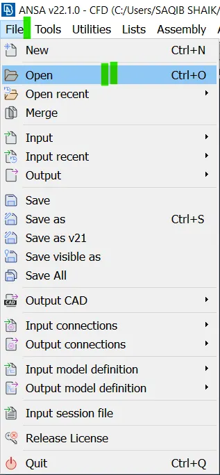
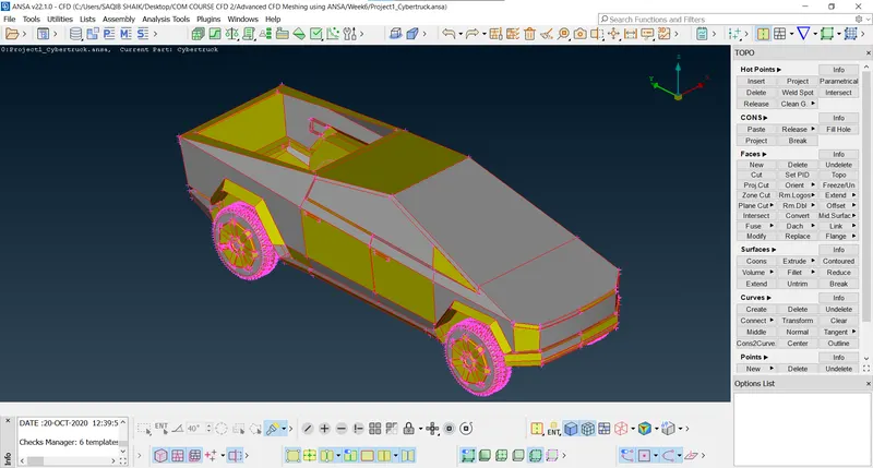
- Import the geometry (File > Open > select the geometry file > Ok):
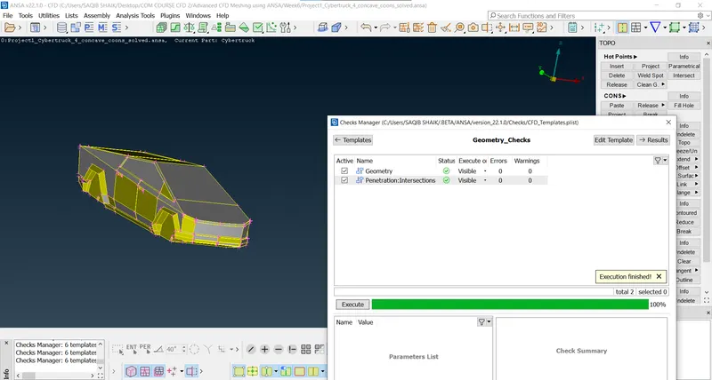
- Run the geometry check to have an idea of errors and warning we are dealing with (Checks > Geometry Checks > Execute):
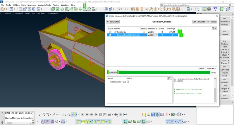
- As we can see there are 9 errors and 37544 warnings, so now lets try to fix it.
- Now the geometry looks like:
- As we can see there are too many single coons we can use the Topo option to fix them (Topo > Right click > Middle mouse):
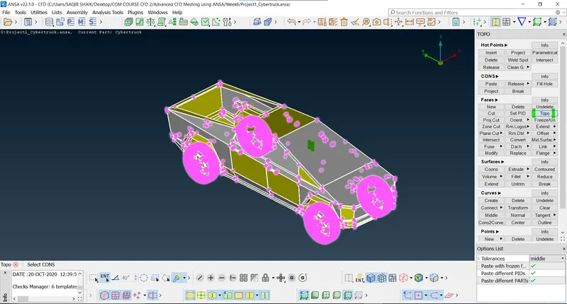
- After:
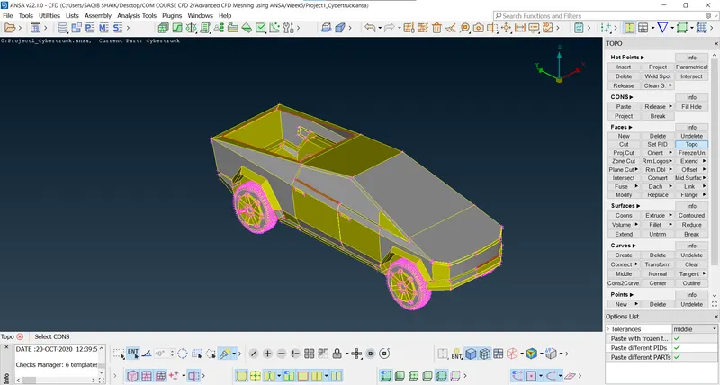
- Now trying to solve the surface errors.
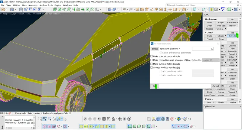
- Left side of the car:
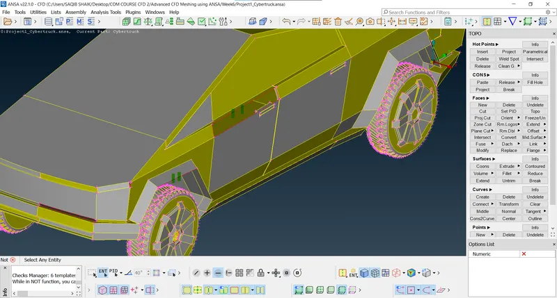
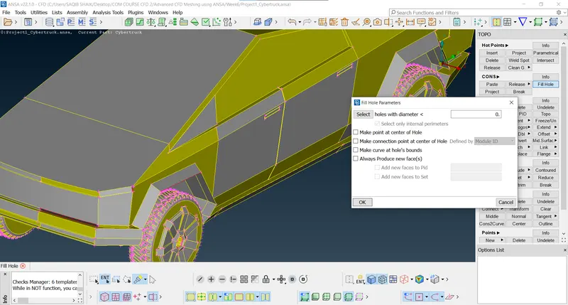
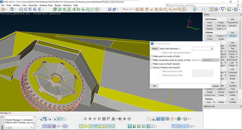
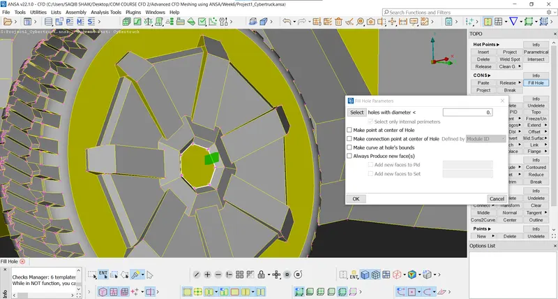
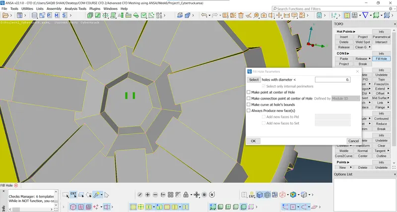
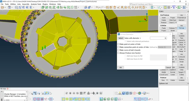
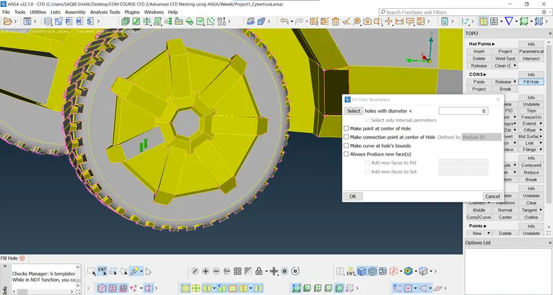
- Using the fill hole command to fill the hole (Fill hole > Select the surface coons > Ok):
- After:
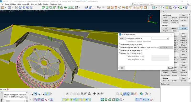
- Wheels:
- After:
- Right side:
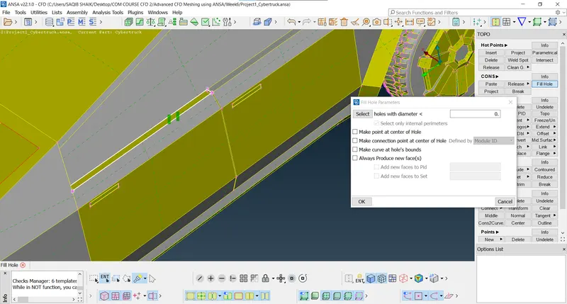
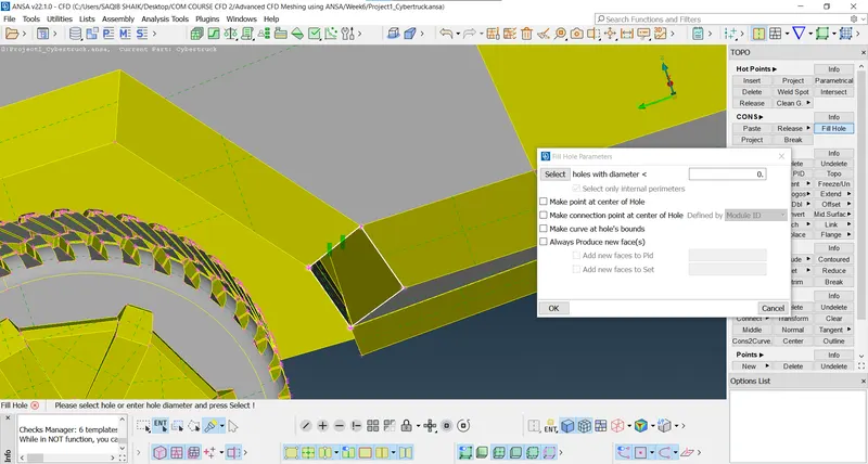
- After:
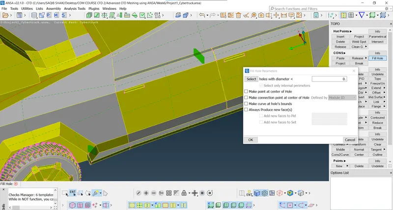
- Front:
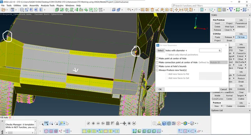
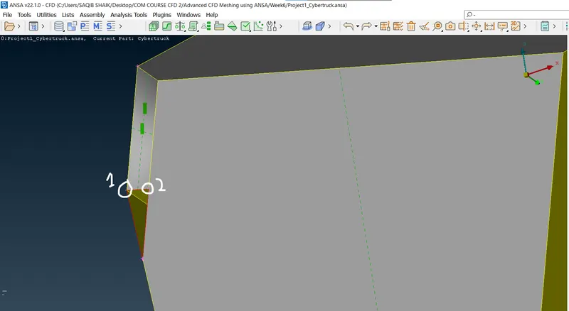
- Projecting the hotpoint from point 1 to 2 as shown (Hot point > project > Select the point > Ok), then create the surface using the coons options:
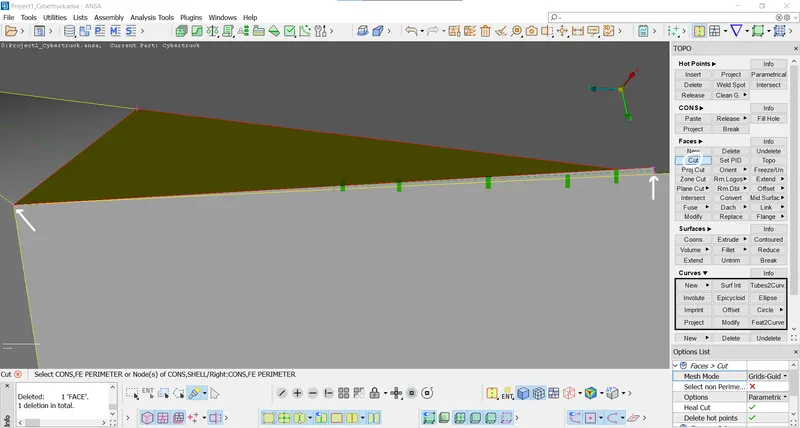
- There is some extra unwanted surface, using the cut option to seperate the extra surface and delete it:
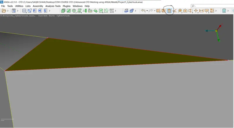
- After deleting the extra surface:
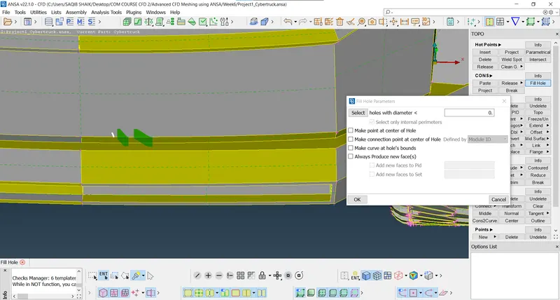
- Using the fill hole command:
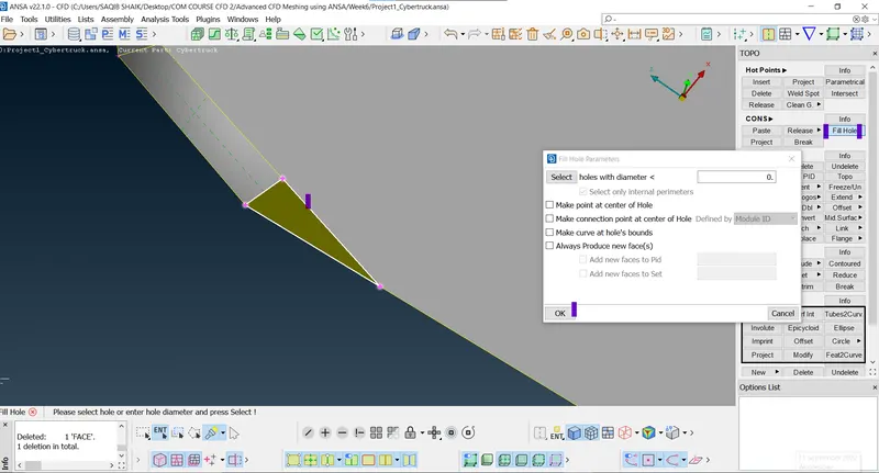
- After fixing:
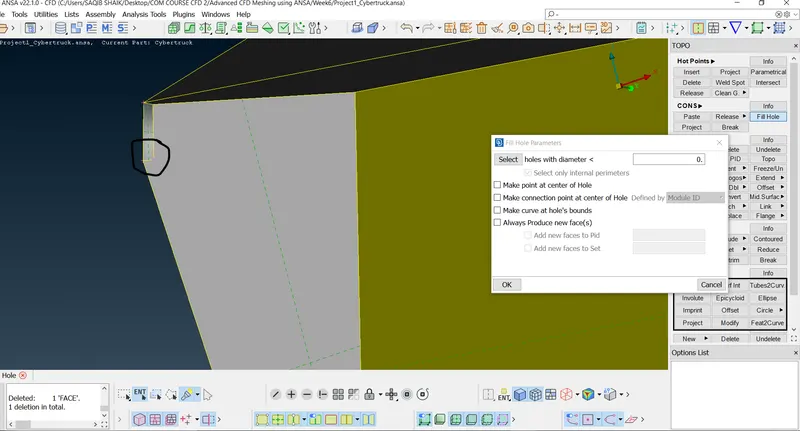
- Other side:
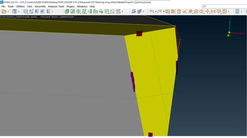
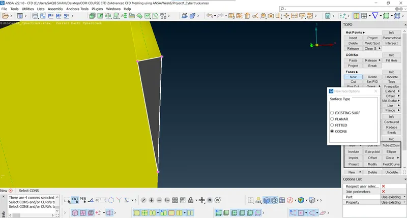
- Project the hotpoint, create the surface using the fitted option:
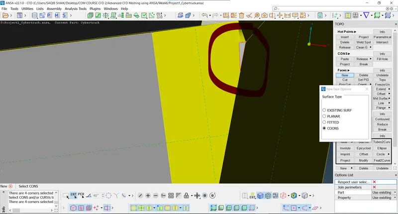
- New surface using the coons options:
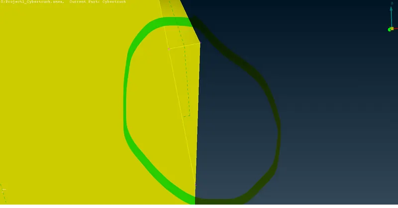
- Both sides has the error at this point but were different and there were many possibilities so, to achieve the maximum geometry retension both the suitable methods described above are followed.
- Back side:
- Boot cover:
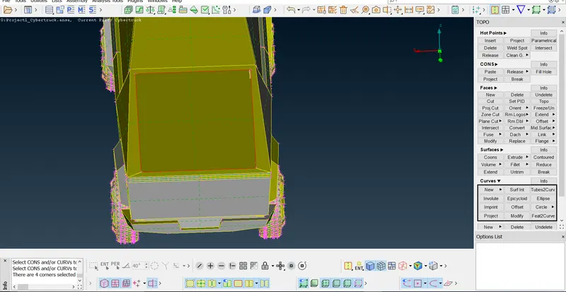
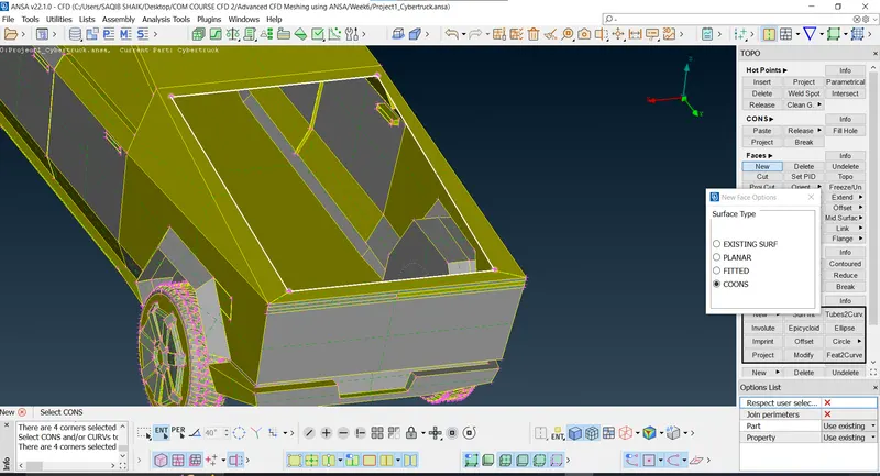
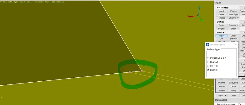
- Creating the missing surfaces:
- Selecting the coons in details:
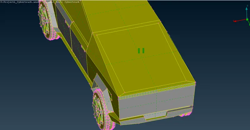
- Mixed coons warnings:
- Peneteration issues:
- Near front right tyre:
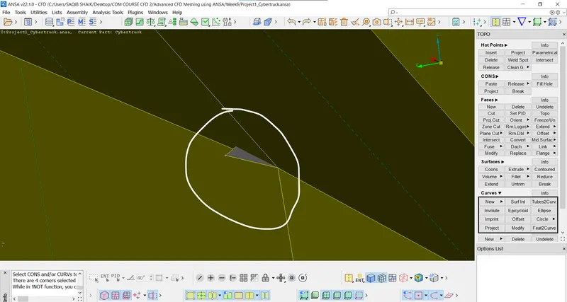
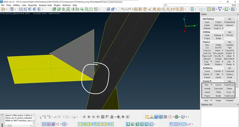
- Now using the cut tools to seperate the surface and delete the penetrating surface and close the single coons:
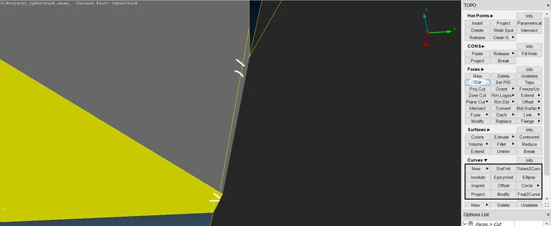
- After deleting the peneterating surfaces:
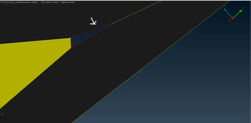
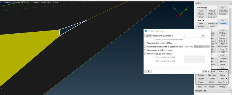
- Using fill hole option to close the single coons:
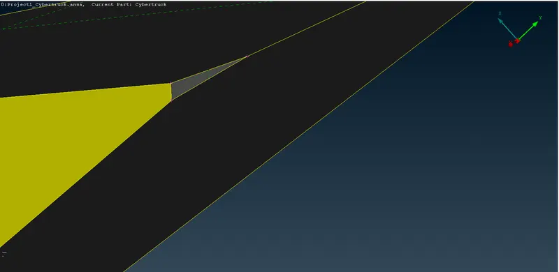
- After fixing:
- Doing on the same other side also.
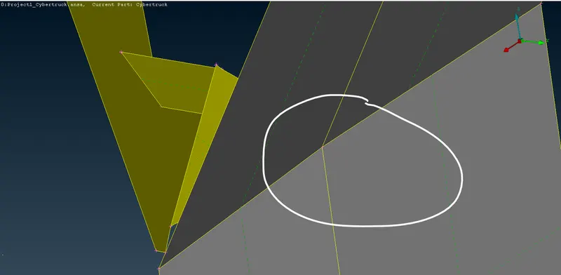
- In the shaft:
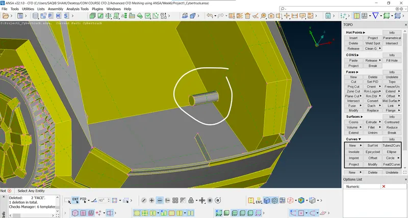
- As there are two seperate surfaces which are connected to housing of the shaft so, deleting the extra shaft and creating the new surface to close the new created single coons:
- Deleting both the overlapping shafts:
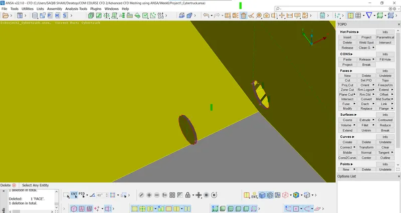
- As the inner surfaces and volumes of the geometry will not play any role in external aerodynamic simulation we can delete and close the single coons with same replicas just to replicate the geometrical morphology:
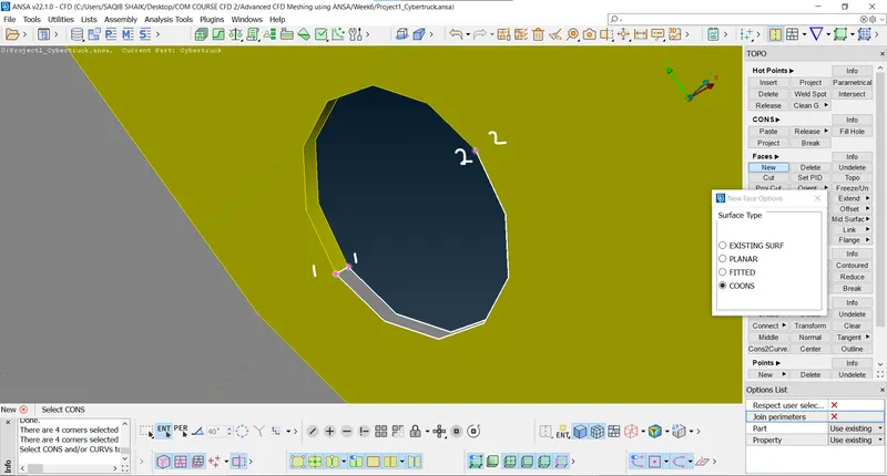
- Projecting the points and creating the new surface to replicate the external exposed portion of the shaft:
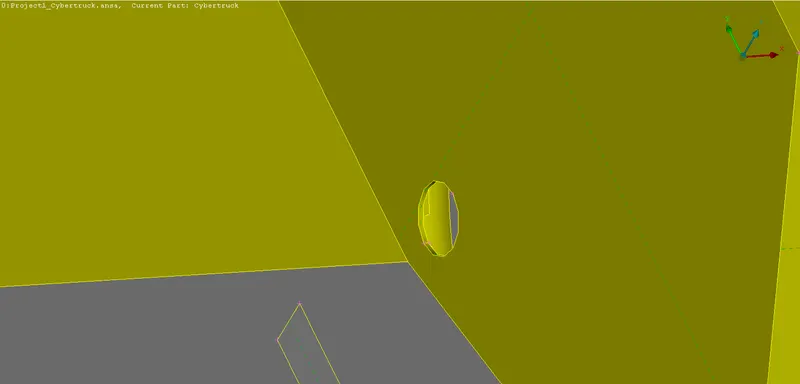
- Following the same procedure for all the four shafts:
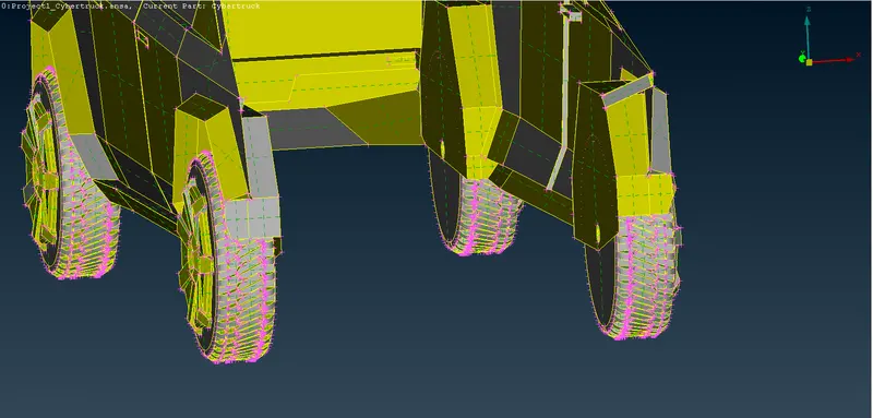
- Mixed coons;
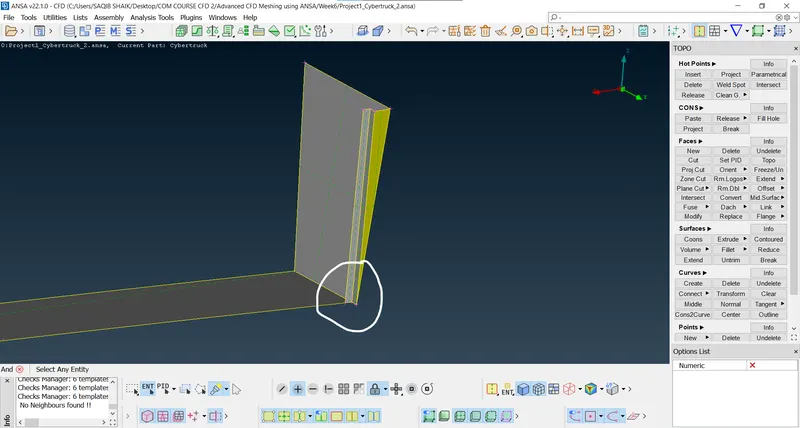
- Using the cut option to seperate the surfaces and delete the warning causing coon:
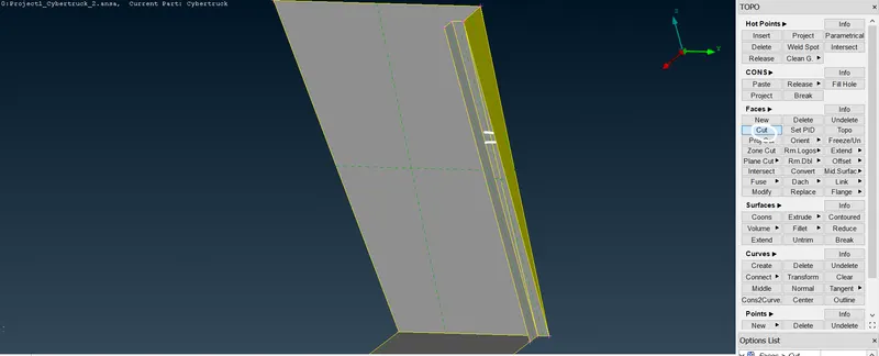
- Deleting and filling the surface using the fill hole options:
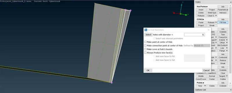
- After:
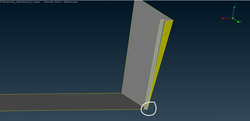
- Doing it on both sides.
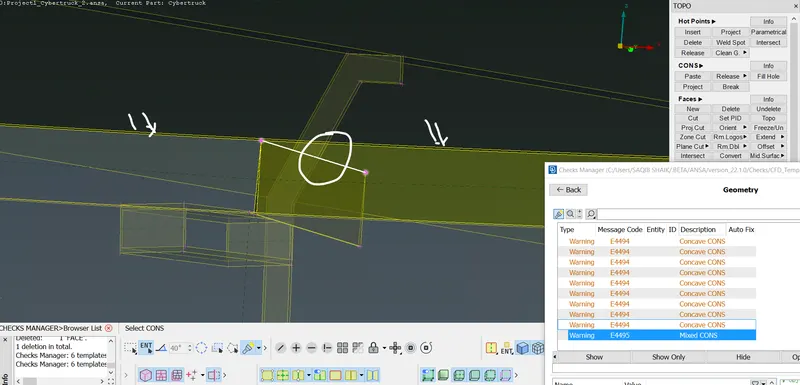
- Deleting the surface and forming the new:
- Delete the two joining surfaces and use the cut option to seperate the surfaces and create the new surface closing them, as these surfaces are very close and with small opening it doesnt have any major effect on the simulation:
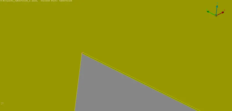
- The mixed coons error warnings are solved.
- Geometry checks:
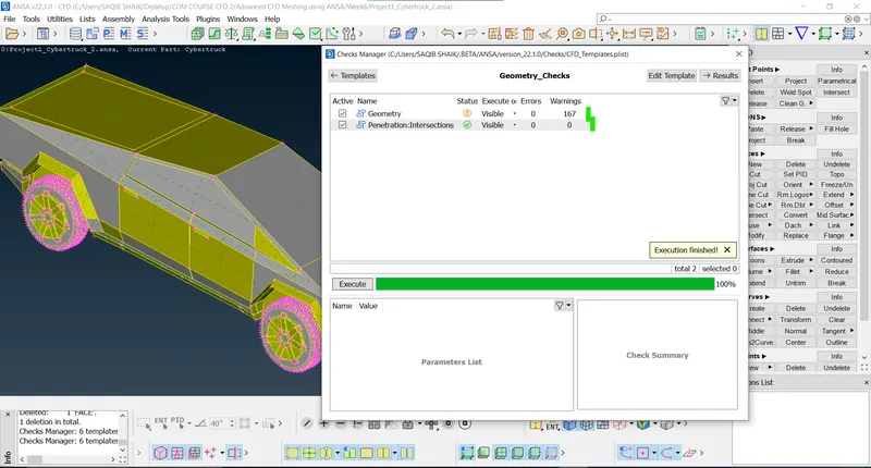
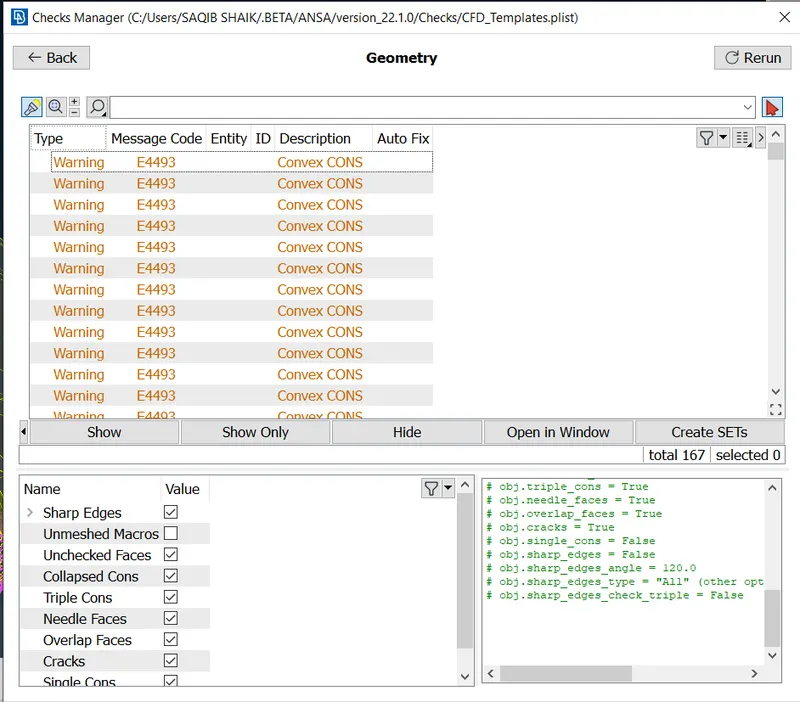
- The door handles, front bumper area and other small space lines like charging port hatch can be closed as they have minimal impact on the aerodynamic analysis but for the accuracy and exact geometry representation we are keeping them for the process.
- After cleaning anf fixing the errors:
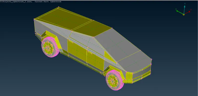
- Now there are 167 convex and concave cooms these are due to the geometry having surfaces with very small angles between them, so we will try both methods:
- Clear all the warnings (may distort the external geometry).
- Keep the convex and concave coons as it will lead to most of the external geometry features retention.
- Case-1 (removing the convex and concave coons):
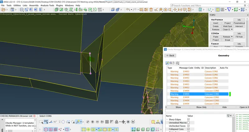
- As this part is not required in the simulation it can be deleted:
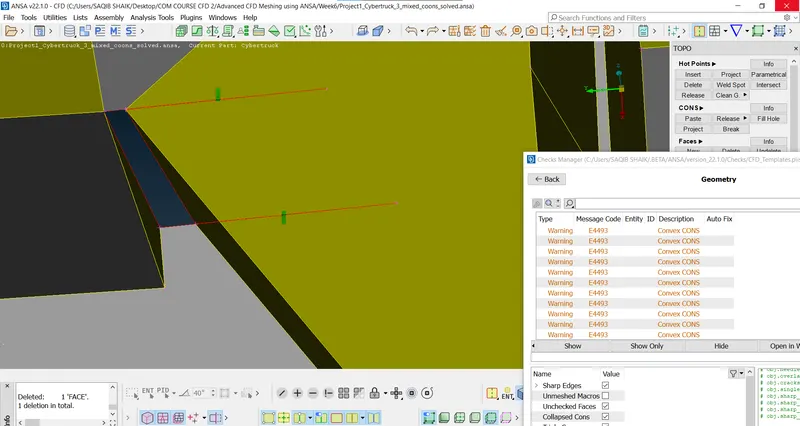
- Using the cut option to seperate the surface and creating the new surface:
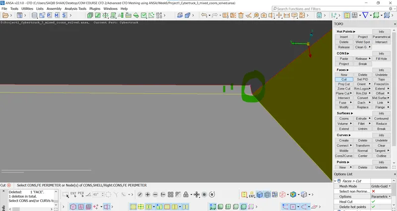
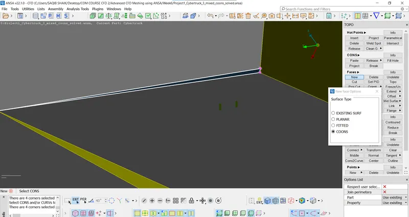
- Fill hole to create the surface:
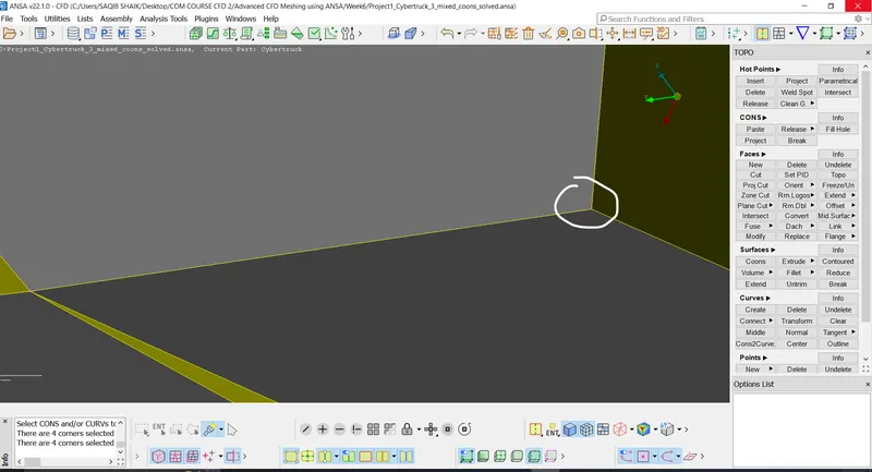
- Doing same on the other side also.
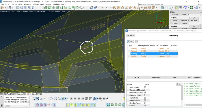
- Deleting the surfaces creating the coons:
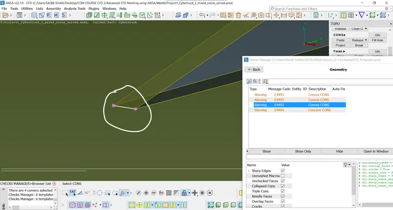
- Using the cuts to seperate the surface:
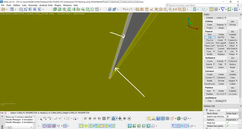
- Deleting:
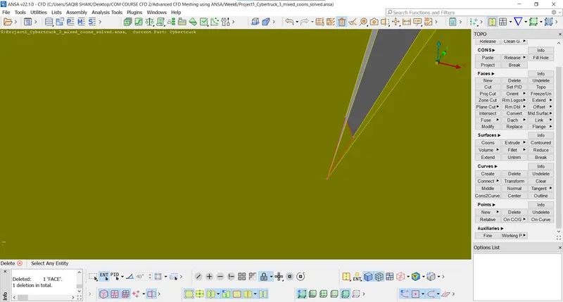
- Creating new surface:
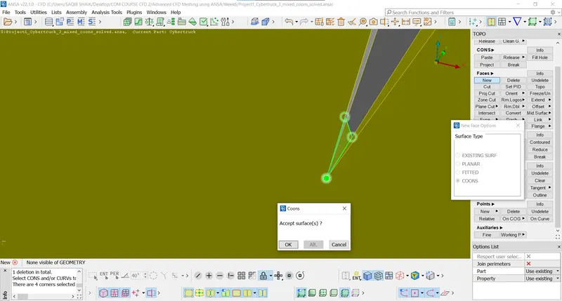
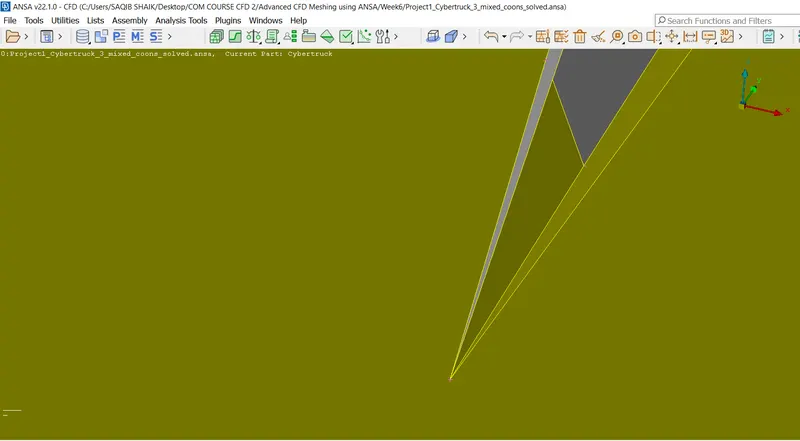
- Doing the same on other side.
- Now there are convex coons on the either side of the front corner so, fixing them:
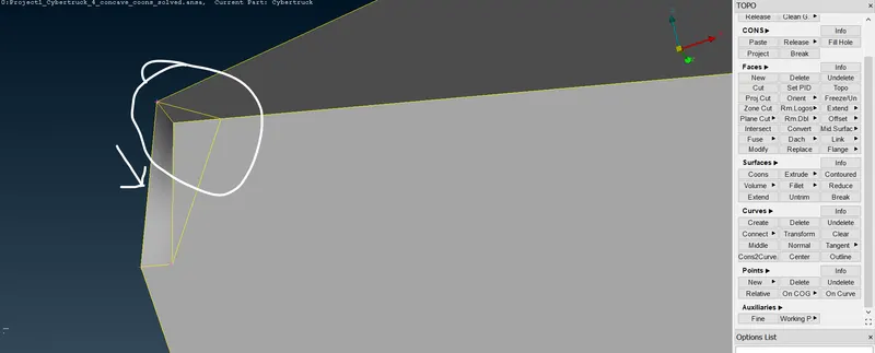
- Cut tool to seperate and create the new surface (with larger angle between them).
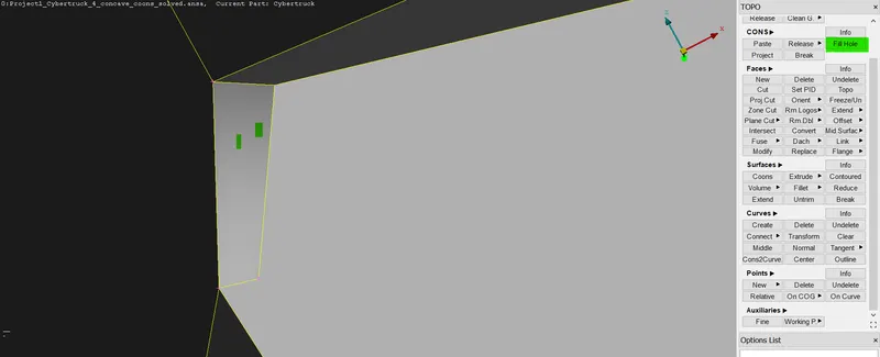
- Completing on both sides:
- Bonnet:
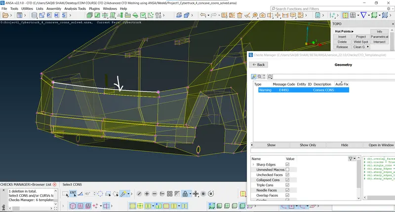
- First delete the surface with low angle using the cut and delete tool and create new surface:
- Deleting the conficting surface:
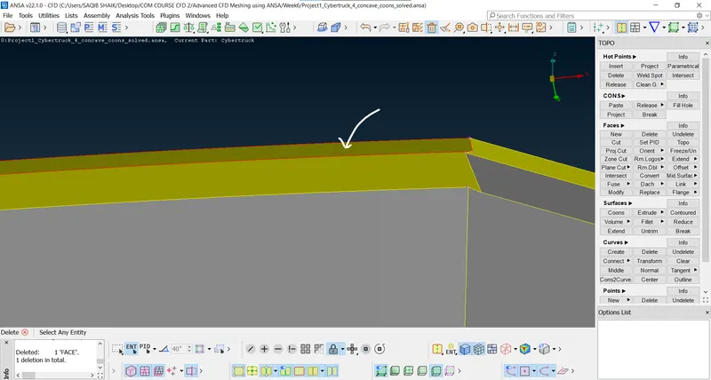
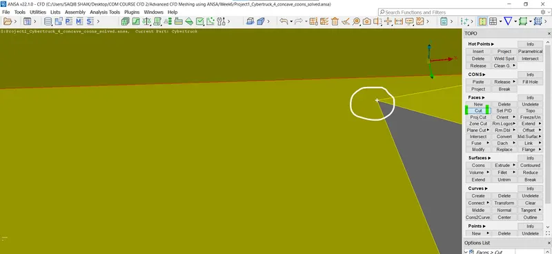
- Cut till next surface:
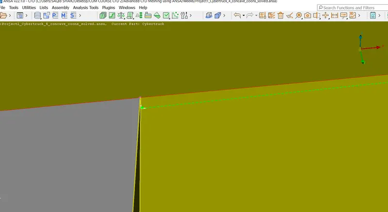
- After several attempts the minimum length to be cut is found and shown below:
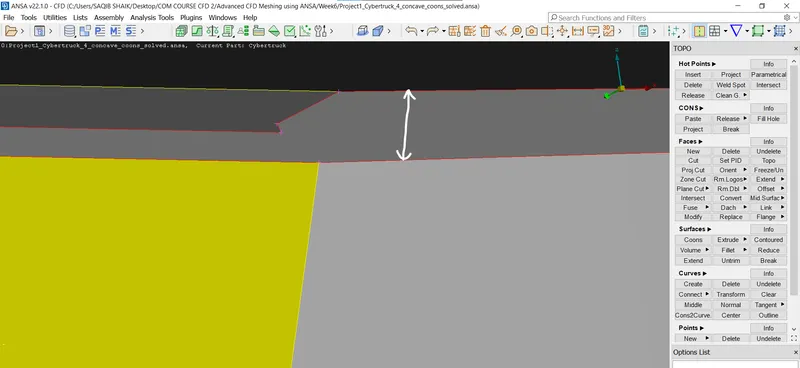
- Symmetry tronsform is done for exact dimensions of the cut on either of the sides.
- And new surfaces are created:
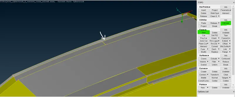
- Closing the open surfaces:
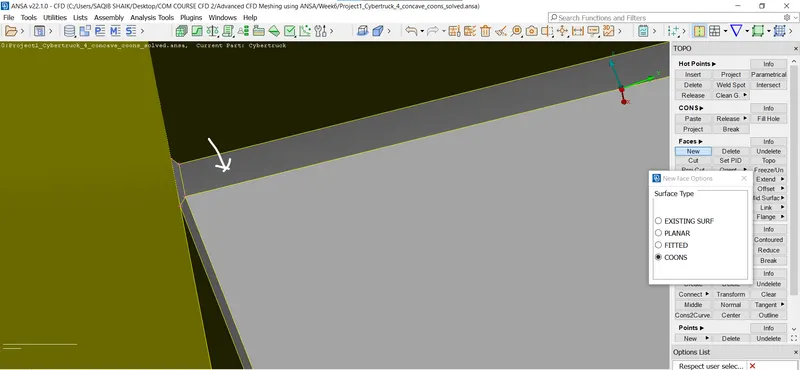
- Checking for errors:
- The remaining convex and concave coons are in tyres only so fixing them is not requried as they are only warnings.
- Proceding with PID's creation/defining:
- Create new shell property (Right click > New > Shell property > Renaming):
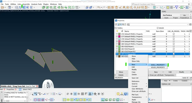
- Renaming to the requried:
- Glass:
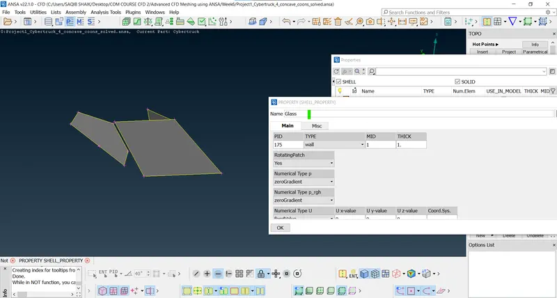
- Select the entities (Right click on the shell property > Apply > select the entities > Ok):
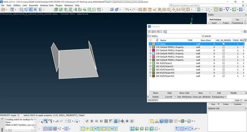
- Rims and tyres:
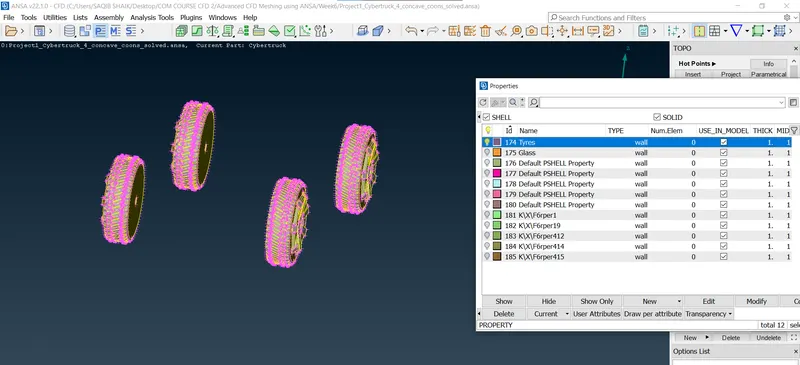
- Bonnet:
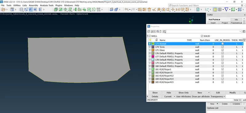
- Body:
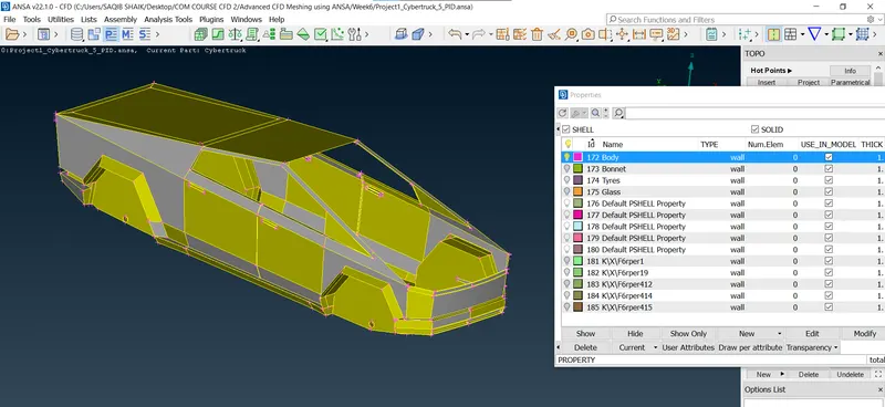
- Compressing to delete the duplicate entities (Compress > All Decks > Ok):
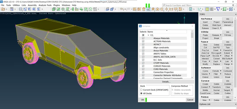
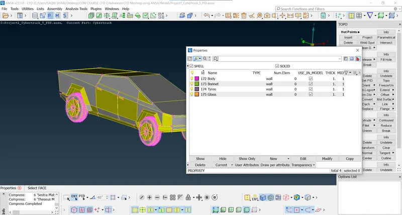
- After compress:
- Meshing:
- Select the Classic mesh option:
- Glass-3mm (2.5-3.5mm):
- Clearing the Off elements using the reconstruct option:
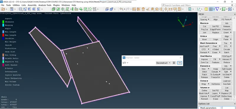
- There are small surfaces causing the skewness error so fixing them:
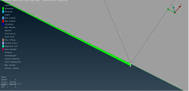
- There is a cut in the window glass which is causing the skewness warning as it is very small section it can be filled and the surfaces can be joined (It doesnt have any major impact on the geometry):
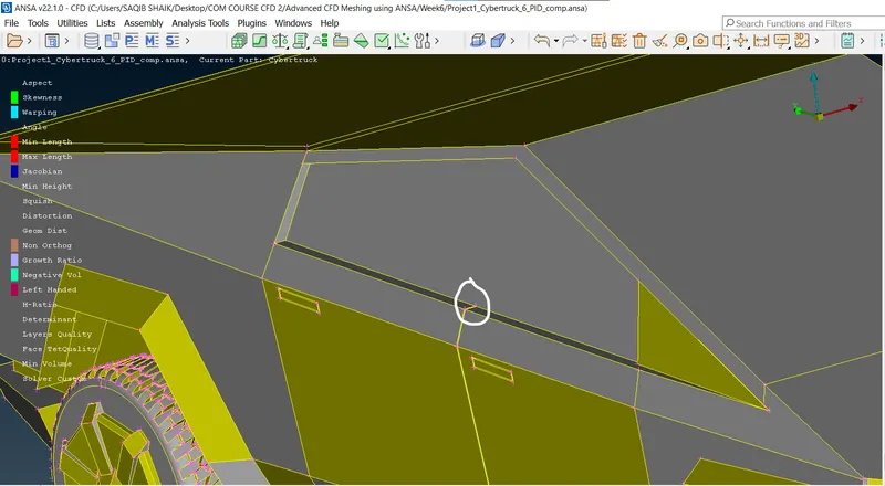
- Interfering notch:
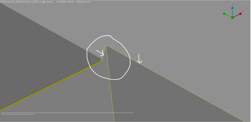
- Creating the curve to form a new face that covers the notch:
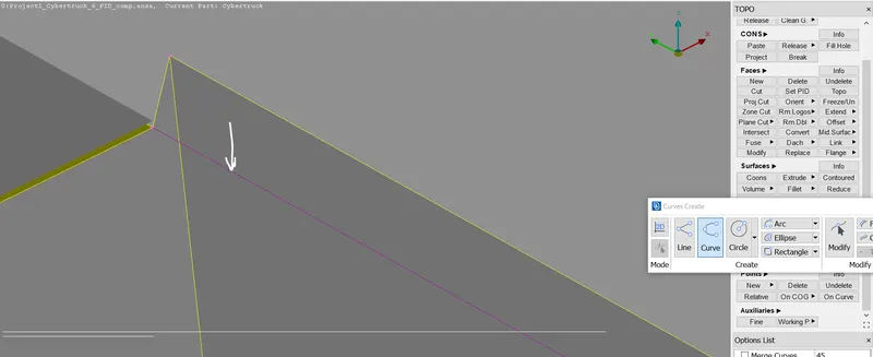
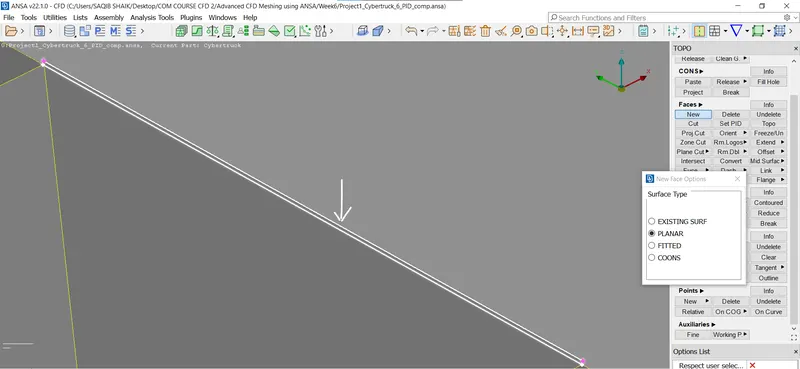
- Creating new surface (planar) and deleting the curve:
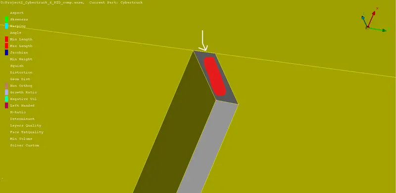
- Delete the red surface and create a new surface and join:
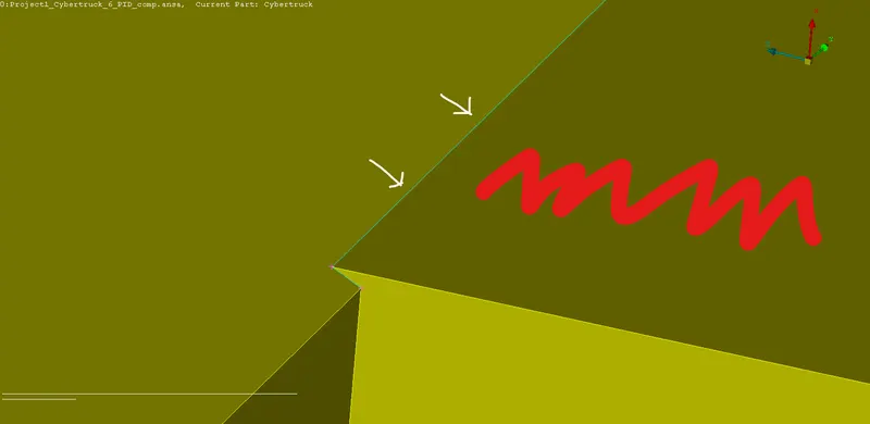
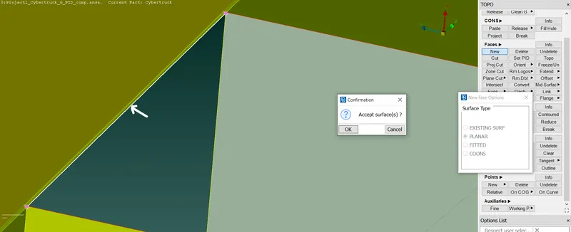
- Deleting the extra surfaces (cut + del) and topo:
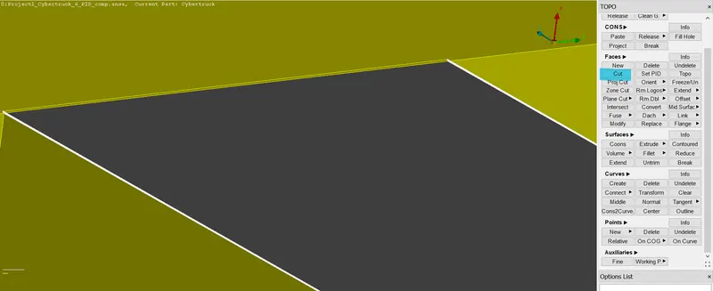
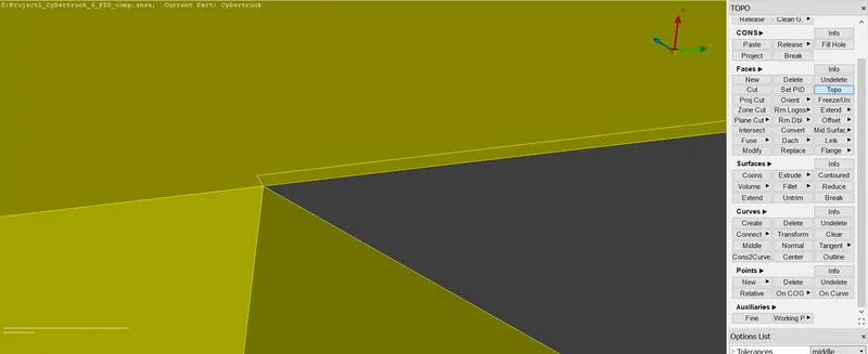
- Removing the unwanted hotpoints:
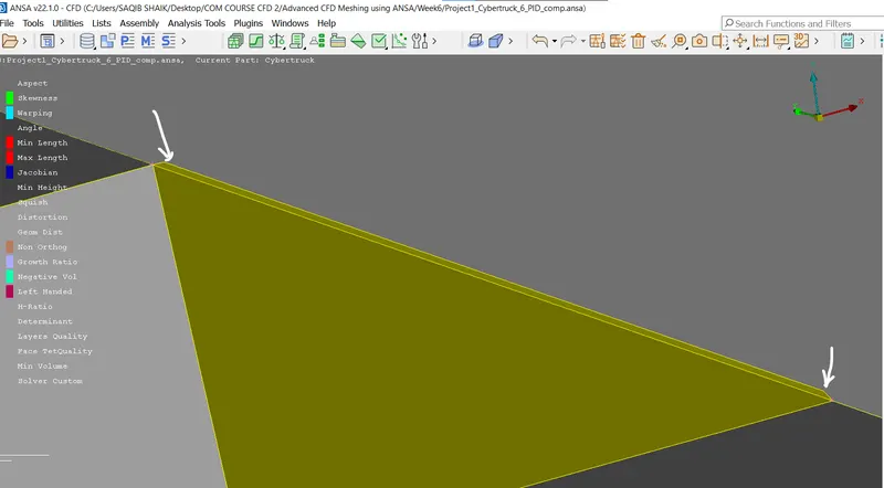
- As there are new surfaces created after the compression we should assign PID's and compress again.
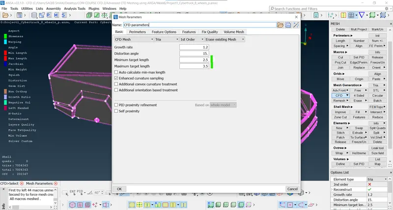
- Meshing (setting the parameters):
- CFD mesh type 2.5-3.5mm:
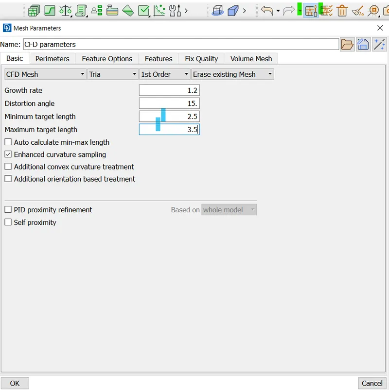
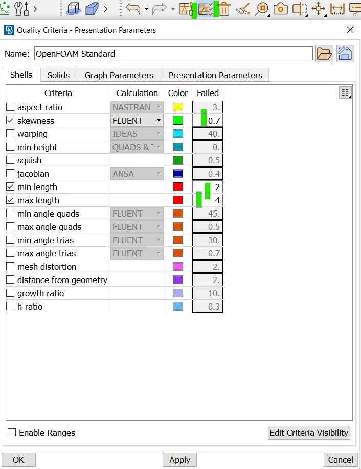
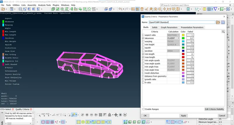
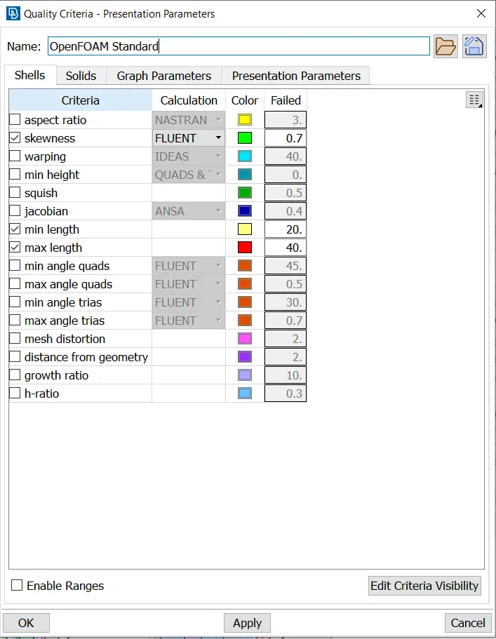
- Setting the quality criterias:
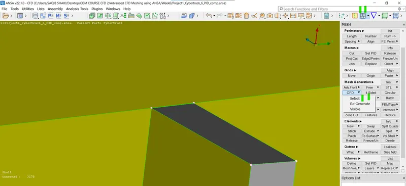
- Mesh using the cfd option:
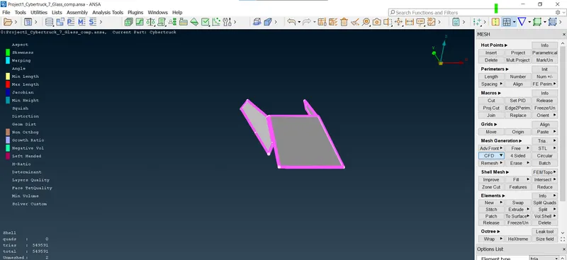
- Selecting with box selection:
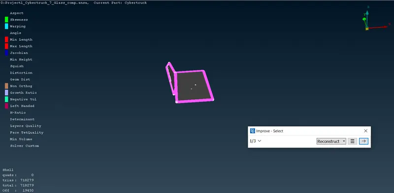
- After meshing and fixing the quality (reconstructing):
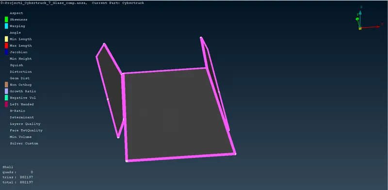
- Freezing the meshed componets as to not distort them while meshing the other components (Freeze/Unfreeze > Right select > Middle mouse):
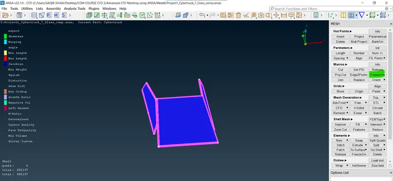
- Following the procedure for all the components.
- Bonnet-3mm (2.5-3.5mm):
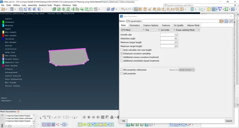
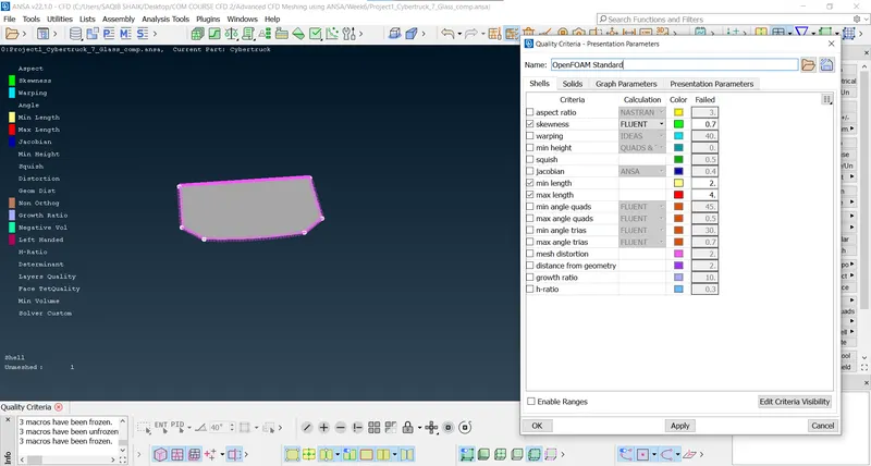
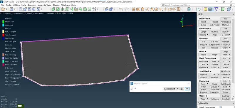
- After meshing and freezing:
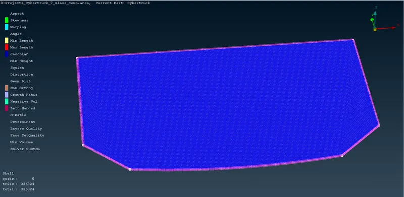
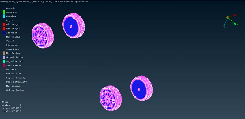
- Tyres and rims-2mm (1.5-2.5mm):
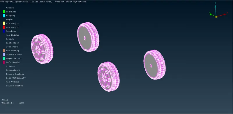
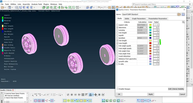
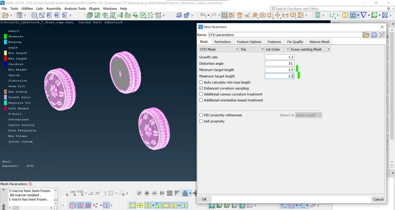
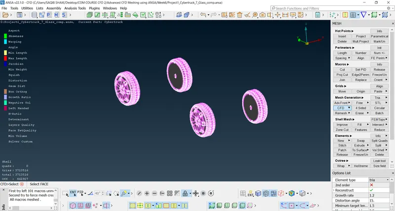
- There are many skewness, mas length and min length warnings for Off elelments which are unable fix with smooth, reshape and reconstruct methods so we should proceed manually using commands like split, move etc.
- There are 4 skewness warnings as there are very narrow faces so, altering them without causing any change external geometry:
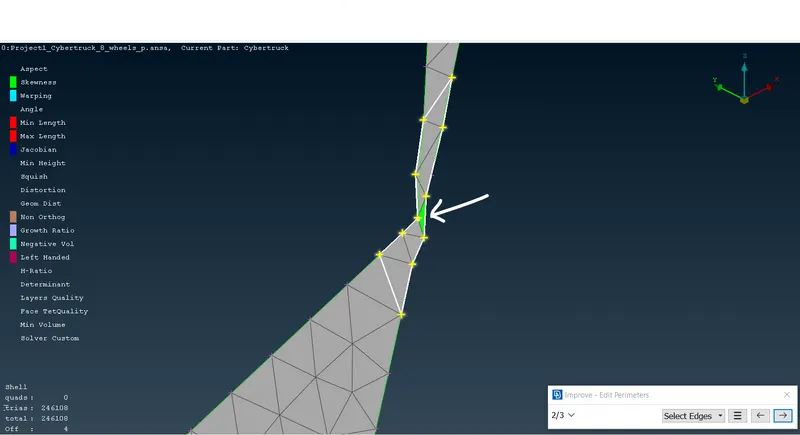
- Using cut commnand options:
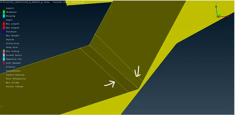
- After creating the surfaces and solving the OFF elements:
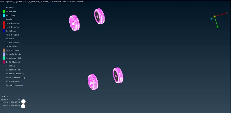
- After freezing:
- Body-3mm (2.5-3.5mm):
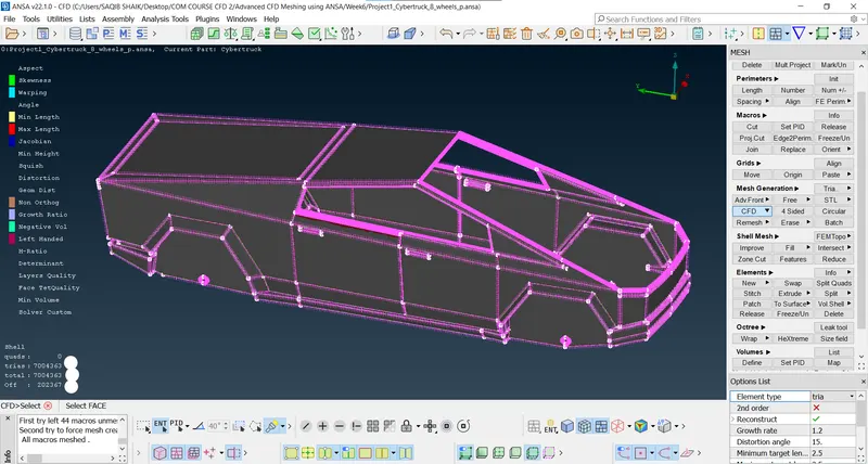
- Reconstructing:
- There are components too small which iscausing the skewness and minimum length warning and as they are too small there is very less impact on the analysis so, deleteing them:
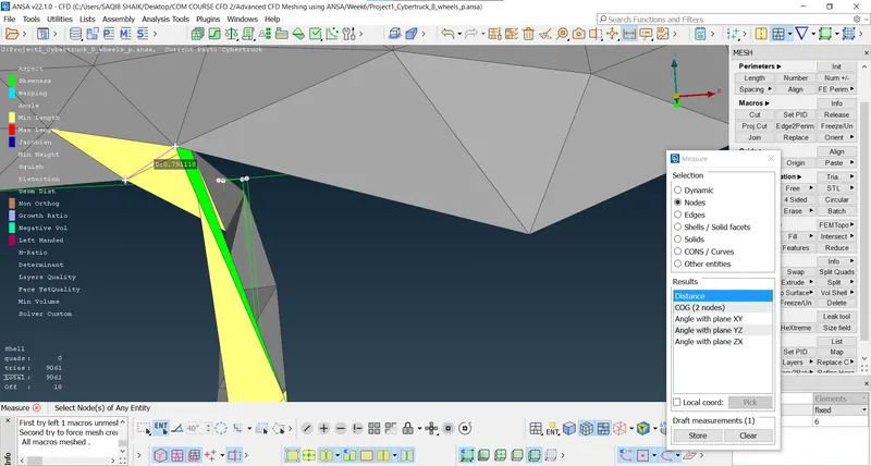
- After:
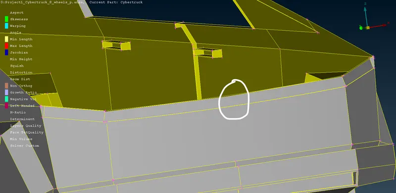
- As there are many other elements which are very less size (i.e. 0.05 mm) have very less impact on aerodynamic analysis:
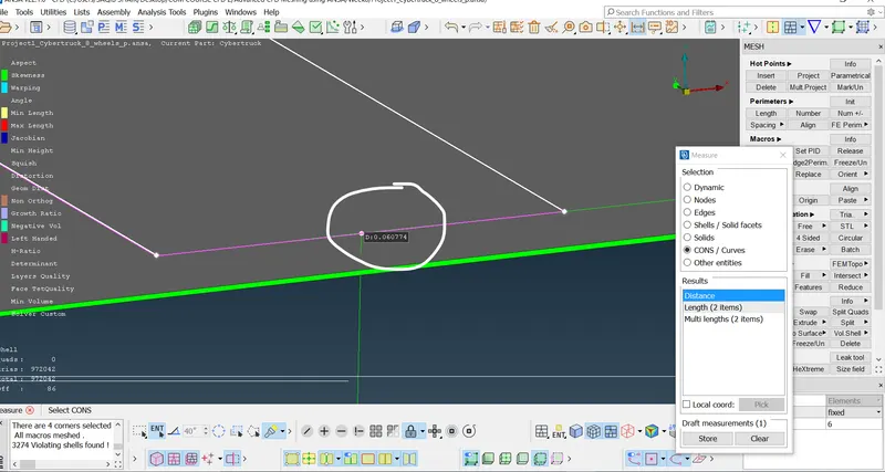
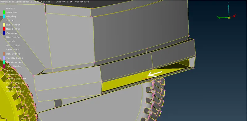
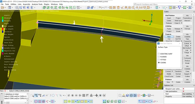
- And creating new surfaces.
- After clearing all the mesh warnings:
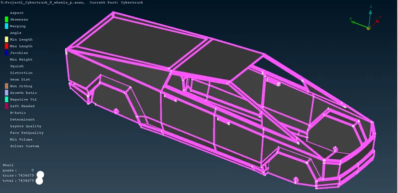
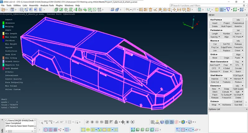
- If all the features of the body needs to be unaltered some parters need to be meshed with a very small element size:
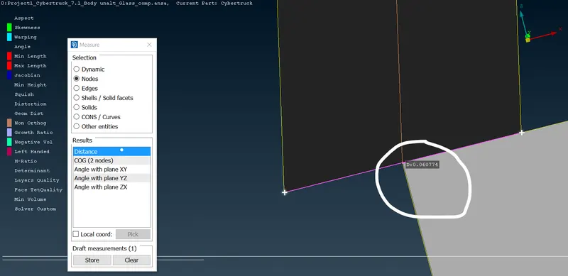
- The element length needed for the 0.03-0.06mm which is less than 0.05mm which is not permitted in the ANSA, even if we try to mesh it with the minimum size it takes more time than volumetric mesh so, proceeding with the body.
- Checking the volumes (volume mesh > Define > Whole body > Ok):
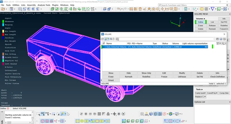
- As there is only one volume which means the geometry is water tight.
- Proceeding to volume creation as enclosure for the windtunnel representation:
- Calculating the dimensions of the vehicle:
- Length of the vehicle (L) - 5800mm.
- Width of the vehicle - 2080mm.
- Distance from the front node to the lowest node vertically is 750mm so while creating the base surface taking 755mm as to keep all the components of the geometry in the windtunnel enclosure.
- All the dimensions are calculated with respect to the car length.
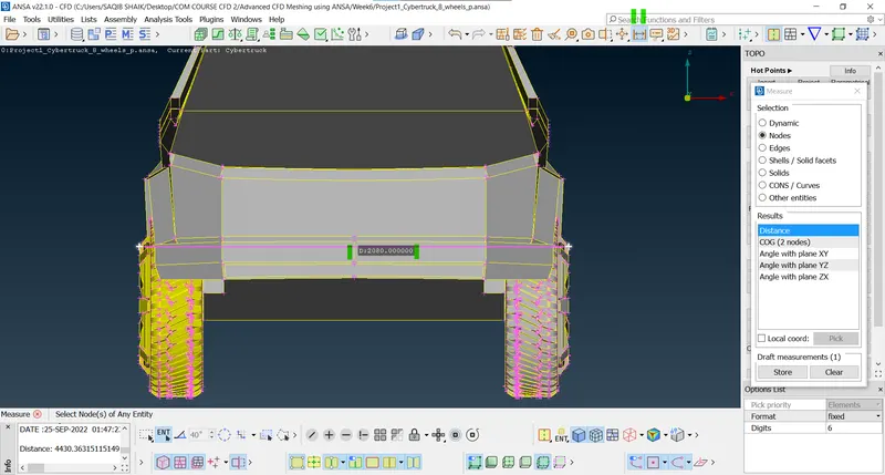
- WindTunnel dimensions:
-
Front 4xL 23200 Back 6xL 34800 Top 3xL 17400 Sides (from centre) 1xL 5800 - Creating the relative points to form a surface (Points > Relative > Select the node > Give the direction and the dimension):
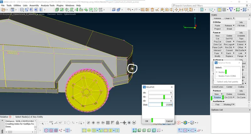
- For clearance:
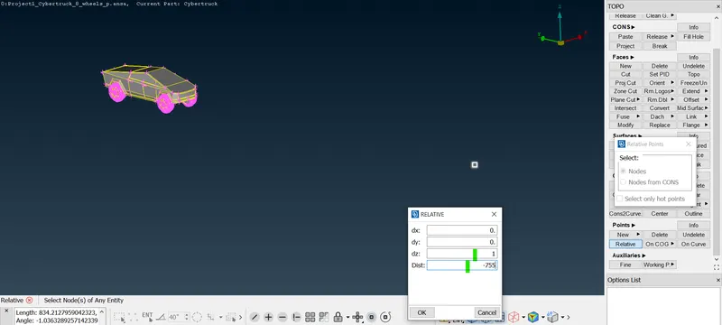
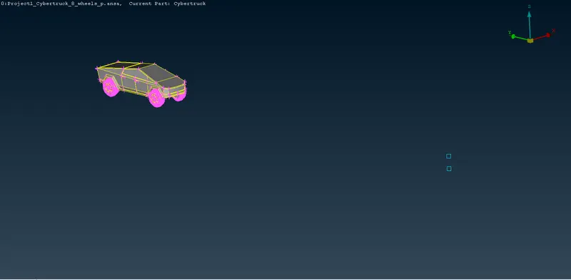
- Creating side points with the lower relative point (5800mm from the centre):
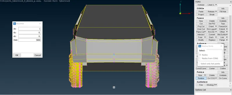
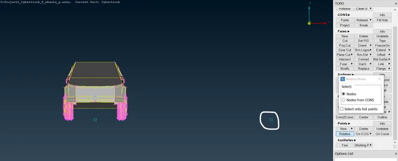
- On the other side:
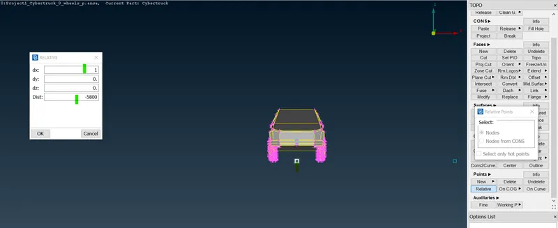
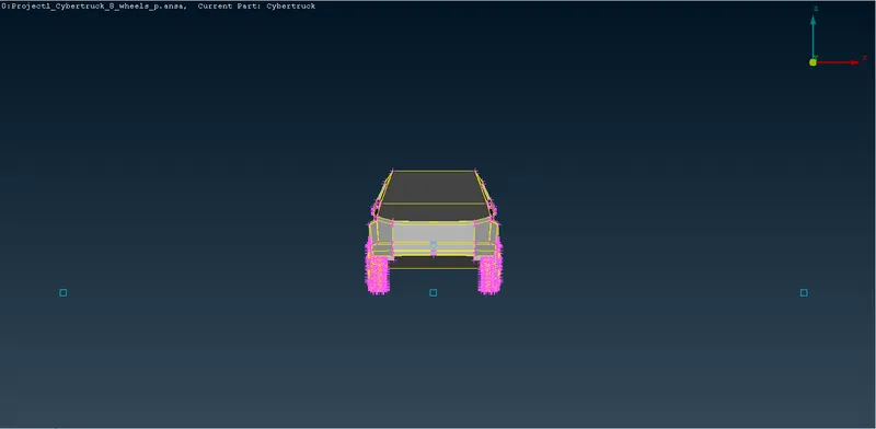
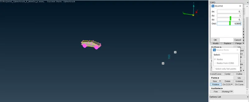
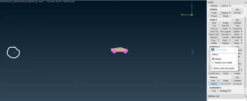
- Now creating the on thback of the geometry which are to be (6x) 34800mm from the last node point of the geometry so with respect to the front points they are at a distance of 11x i.e. 63800mm.
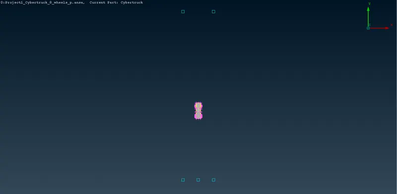
- Creating the surface by using the curves to join the points after deleting the unwanted points (Curves > Create > Select points > Ok):
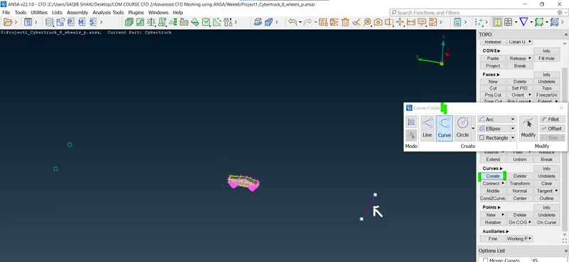
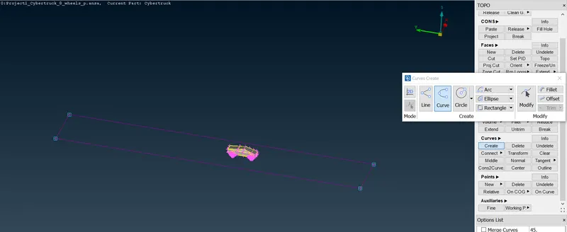
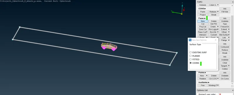
- Now creating the surface (Faces > New > Type-Coons > Select the curves >Ok):
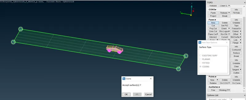
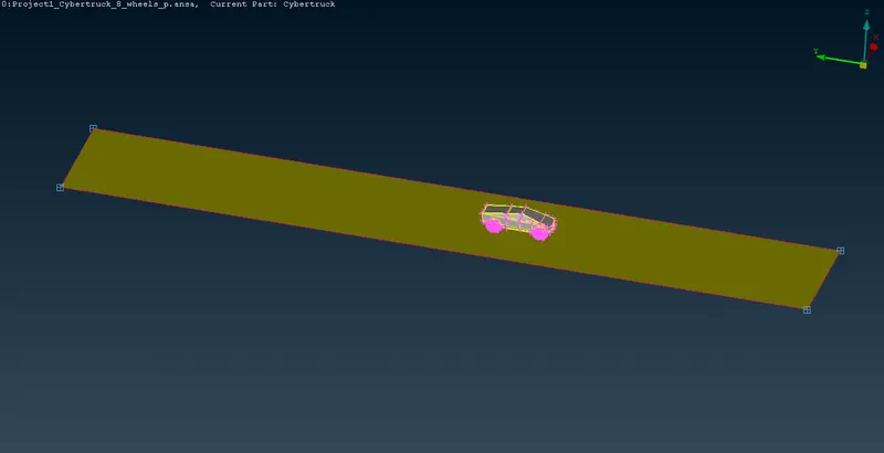
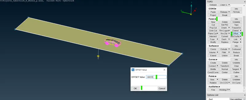
- Using the offset option to create the top surface (Faces > Offset > select the faces > give the offset value > Ok):
- Offset value = 3x + clearence + vehicle height = 17400+1900 = 19300 mm.
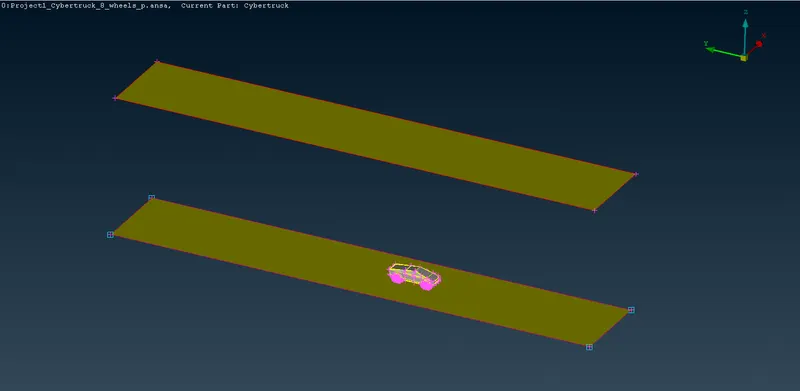
- Deleting the points and curves and creating new surfaces to complete the windtunnel enclosure:
- Front:
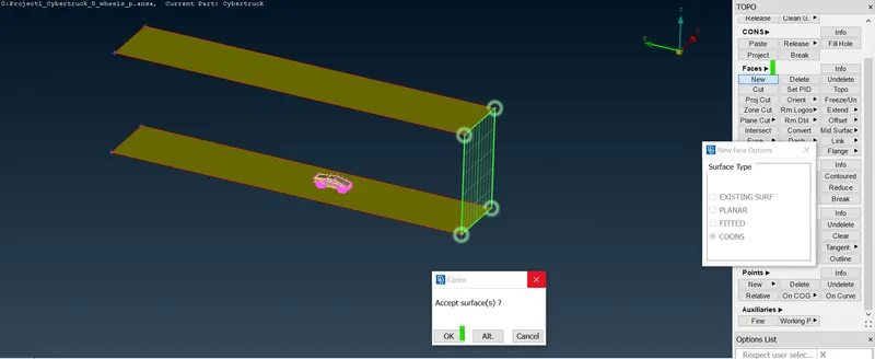
- Left side:
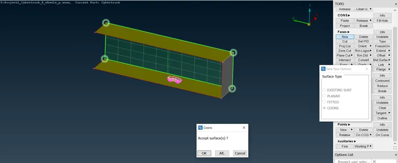
- Back side:
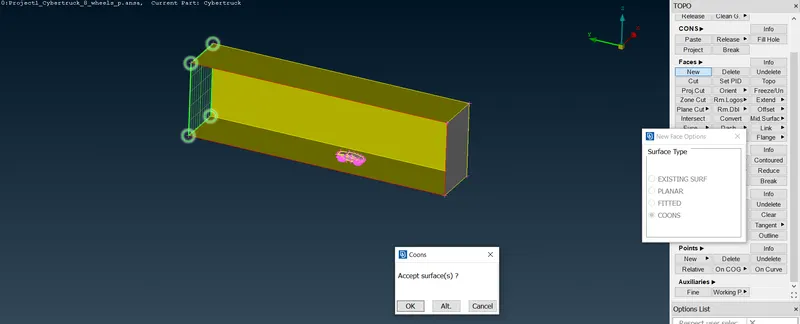
- Right side:
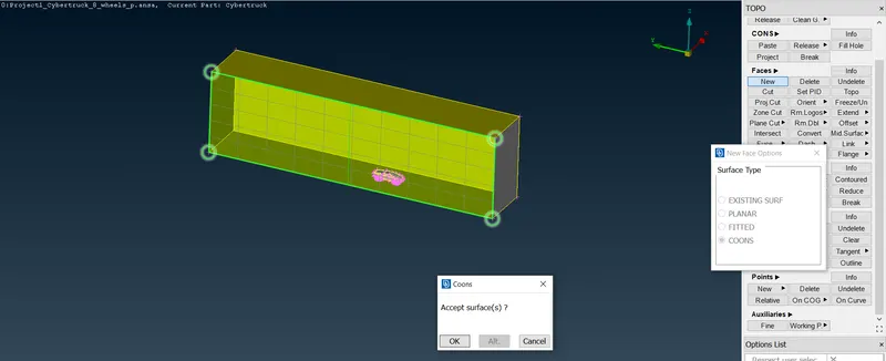
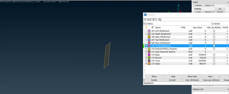
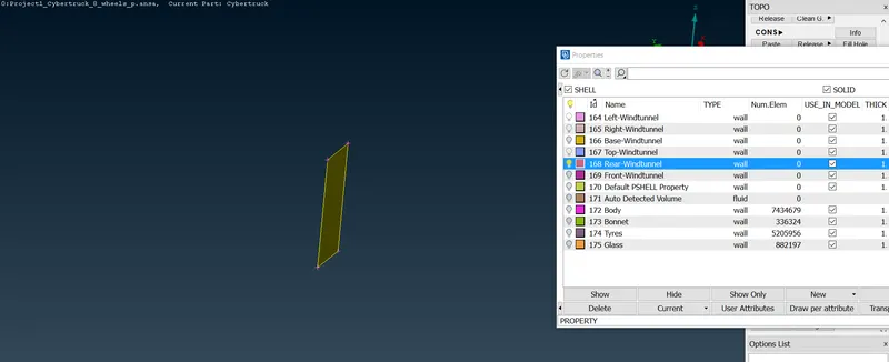
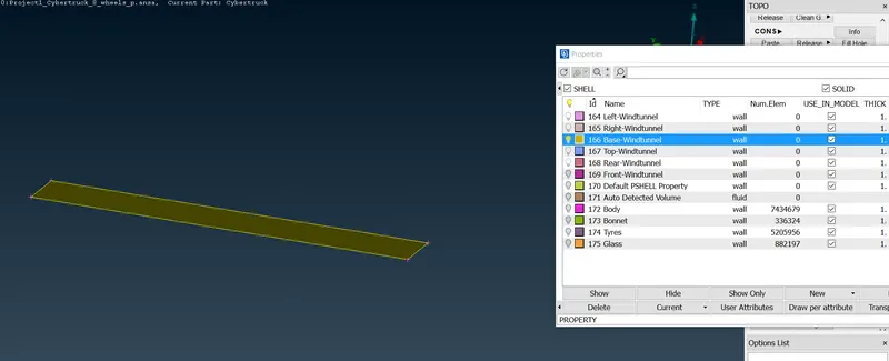
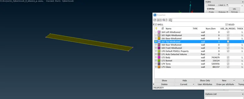
- Defining the PID's for windtunnel surfaces:
- Front:
- Rear:
- Base:
- Top:
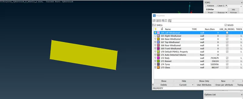
- Left:
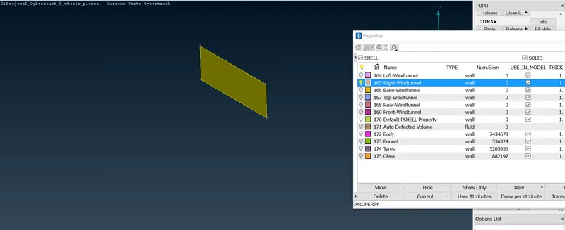
- Right:
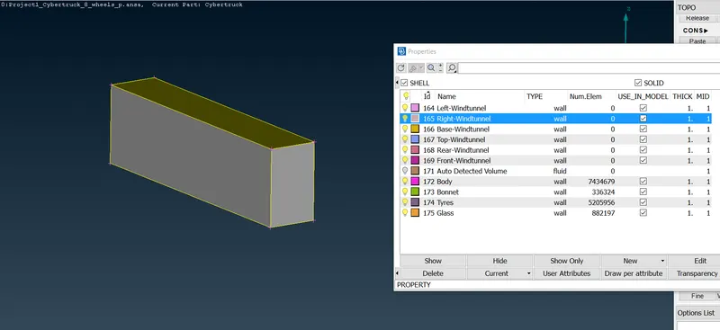
- Using the compress option to clear the duplicate or previous PID's:
- Now as the windtunnel enclosure is ready we are ready to mesh:
- Surface mesh for the windtunnel:
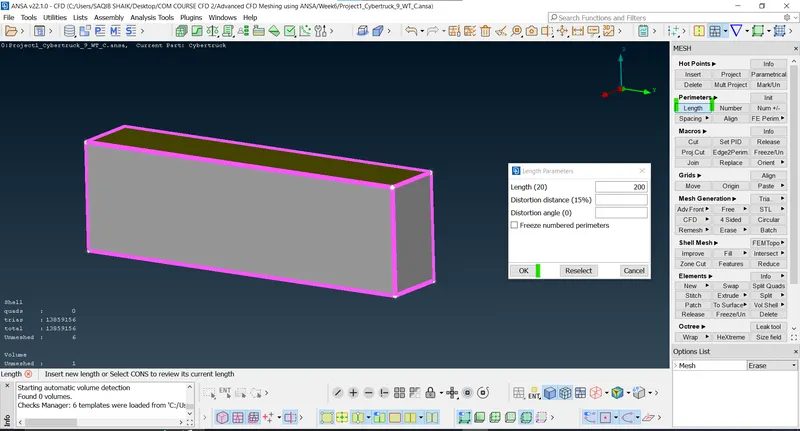
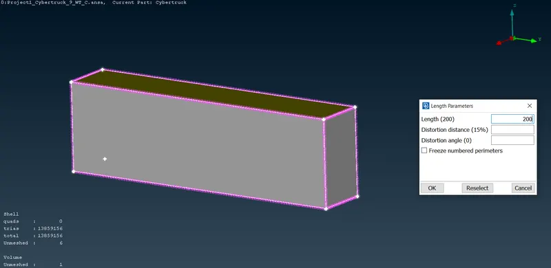
- Defining the length (200mm) (Classic mesh > Perimeters > Length > Select the geometry > define the size > Ok):
- Macros(200mm):
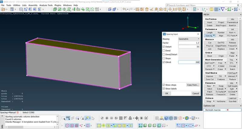
- Now as we are interested in the area near the vehicle we need to have a very finer mesh near the vehicle and gradually increase the mesh size depending on the quality.
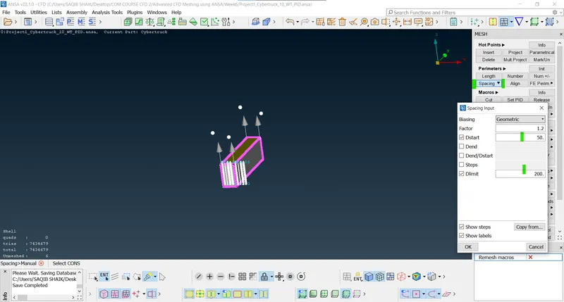
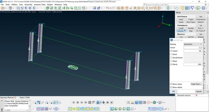
- For this reasons the verticle edges of the windtunnel are meshed using the variable bias starting from 50mm and ending at 200mm (Spacing > define start and end limit > Ok):
- Selecting the edges:
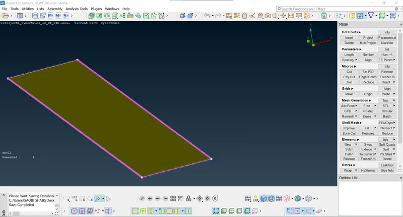
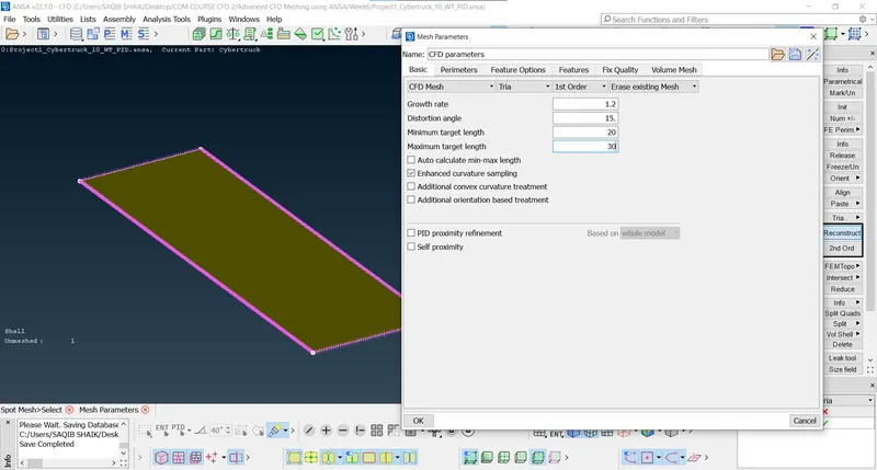
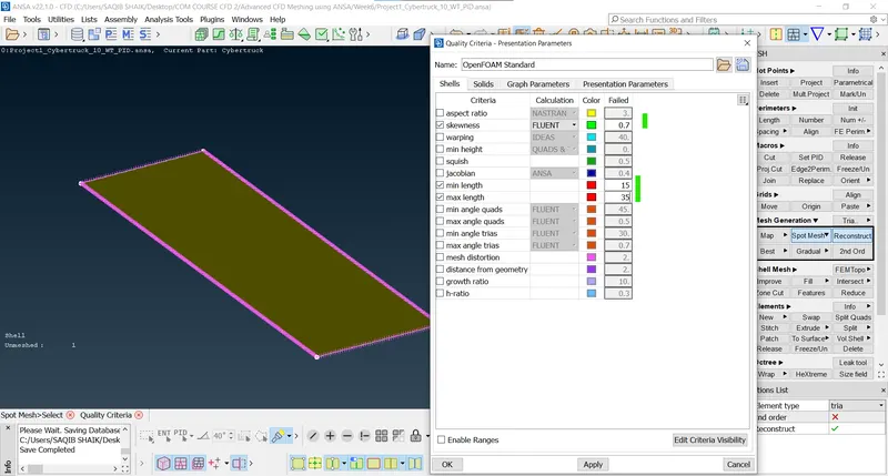
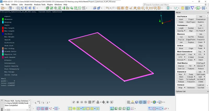
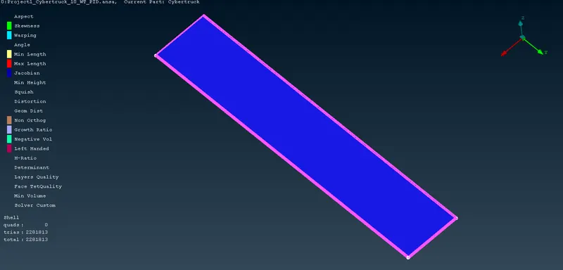
- Meshingthe base of the windtunnel-25mm (20-30mm):
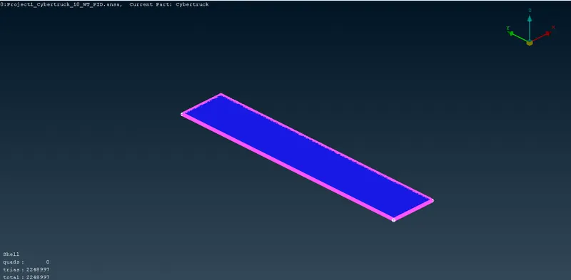
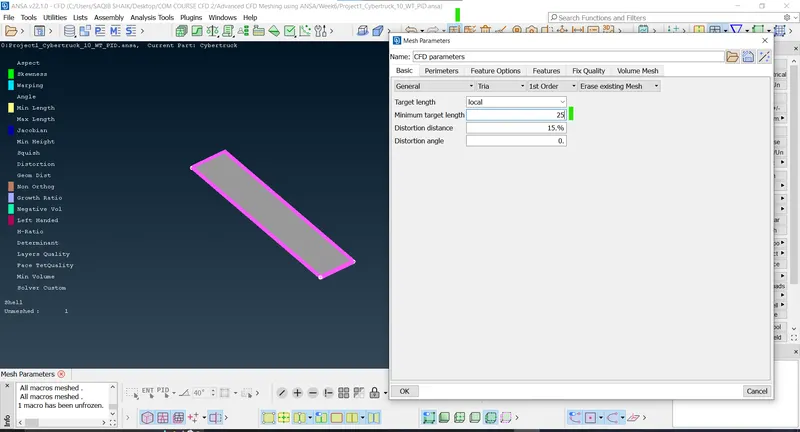
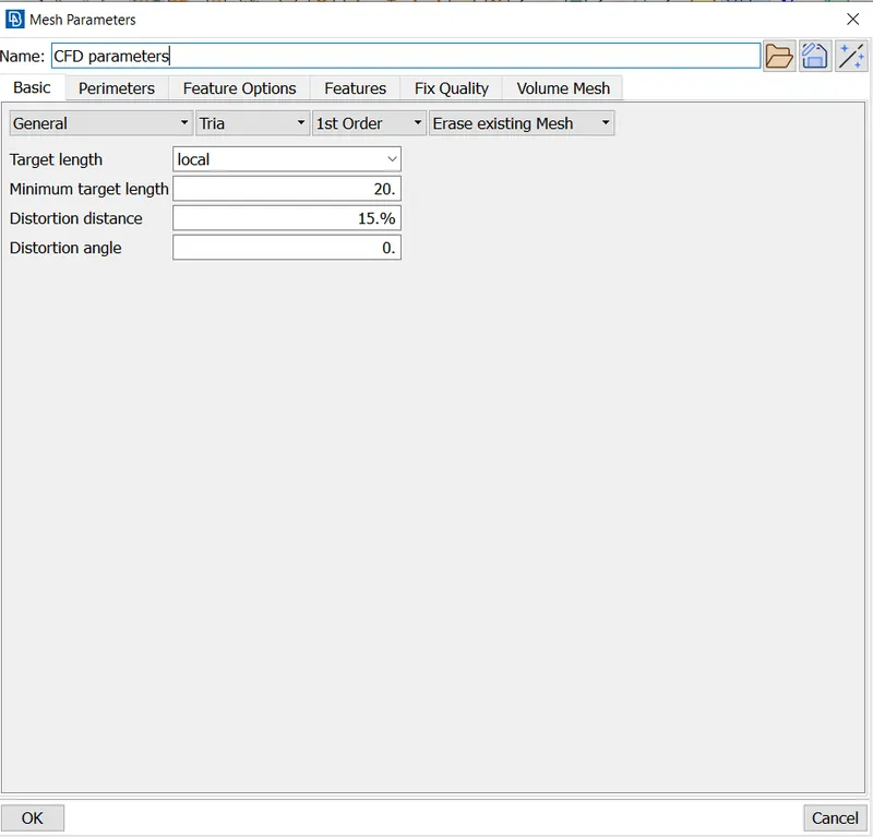
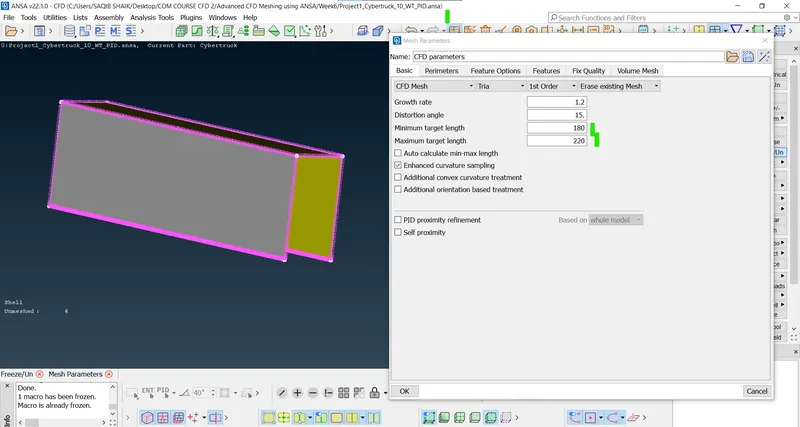
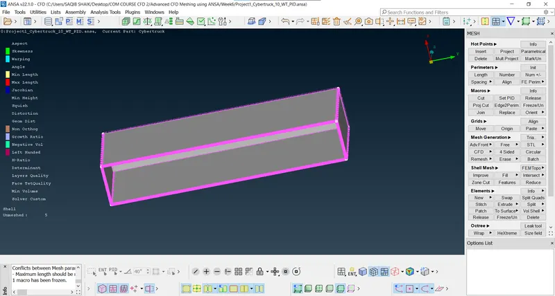
- Top, left, right and rear surfaces-200mm (180-220mm):
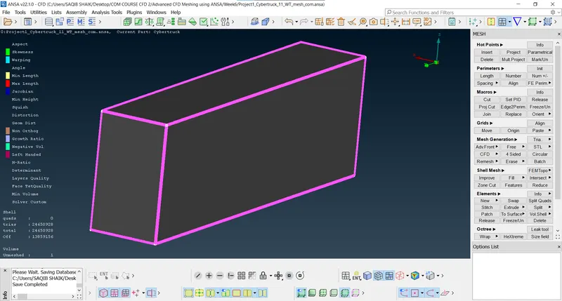
- After surface mesh ic completly done:
- Volumetric meshing (Select the volumetric mesh):
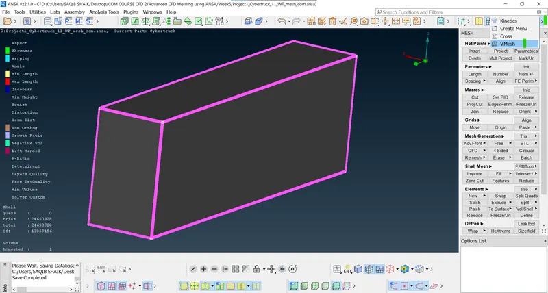
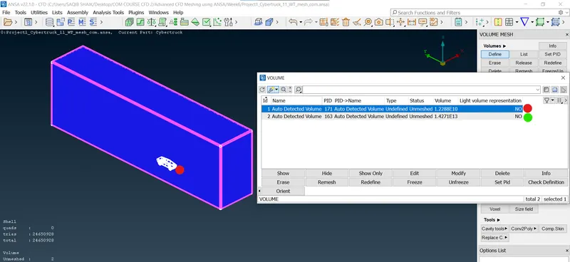
- First we need to check and select the external volume to mesh (Volume > Define > Whole db > Ok):
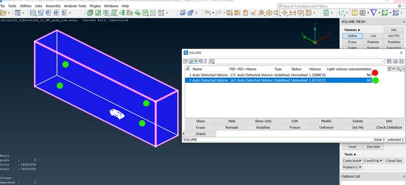
- There are two volumes in the geometry:
- Vehicle interior volume.
- Wind Tunnel volume (i.e. Space between the vehicle and the external enclosure).
- We should delete the Vehicle space and only mesh the exterior volume because we are analysizing the external flow over a the vehicle (Select the volume > right click > delete > Ok):
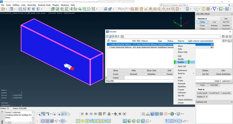
- Now for the remaining volume we will perform the volumeteric mesh.
- As the perimeters, macros and bias are already defined we can proceed with volumetric mesh.
- Vehicle interior volume.
- There are two volumes in the geometry:
- After volumetric meshing:
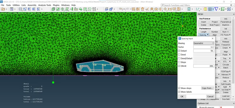
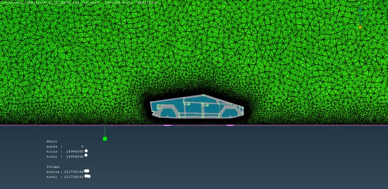
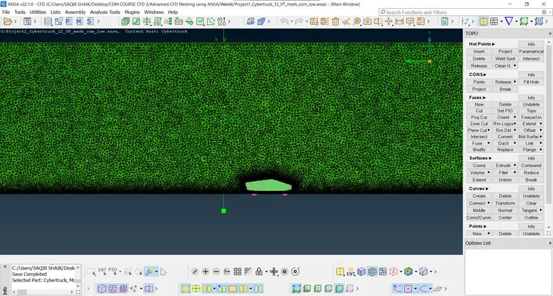
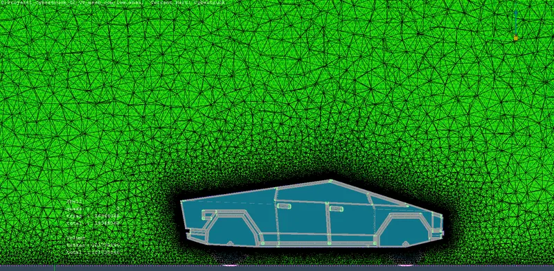
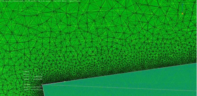
- There are more than 12 crore volumetric mesh elements in total.
- Now the geometry is ready to undergo simulation.
Results:
- Imported and clean the raw geometry:
- Geometry mesh:
- Dimensions:
-
Sl.no. PID Element size (mm) Range (mm) Min-Max Min/Max length criteria (mm) Skewness 1 Body 3 2.5 - 3.5 2/4 0.7 2 Glass 3 2.5 - 3.5 2/4 0.7 3 Bonnet 3 2.5 - 3.5 2/4 0.7 4 Rims and Tyres 2 1.5 - 2.5 1/3 0.7 5 Windtunnel 25 25-150 20/180 0.7
-
- Rims and tyres:
- Windshield and window:
- Bonnet:
- Body:
- Complete vehicle geometry meshed:
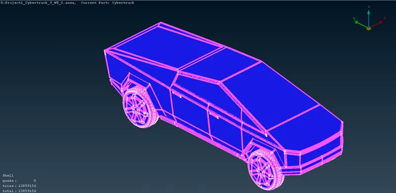
- Dimensions:
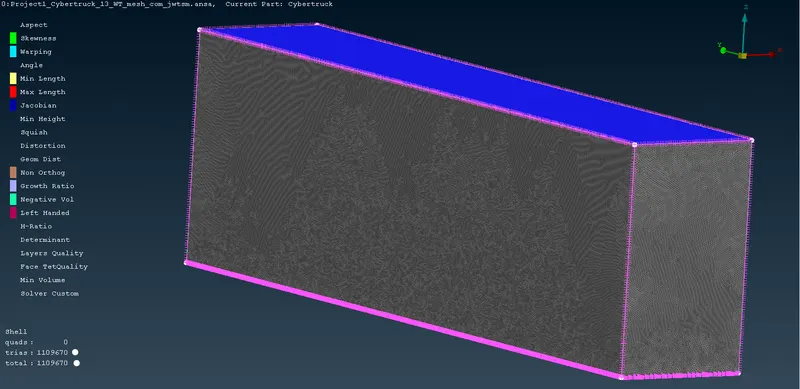
- Windtunnel surface mesh:
- Dimensions:
-
Front 4xL 23200 Back 6xL 34800 Top 3xL 17400 Sides (from centre) 1xL 5800 - The Off elements were fixed.
- Volumetric Mesh:
- First delete the volume not requried.
- Thenn using the tetra rapid option in the volumetric mesh select the geometry and create a volumetric mesh.
Leanerning outcomes:
- In this challenge the cleaning of the geometry is very detailed as there are very sharp edges causing the errors which helped to learn new ways and upskill my knowledge about pre-processing.
- Dealing with the larger geometry leads to problems for computation so we should choose the best out of geometry.
- Technicalities of the windtunnel and meshing the volume to the appropriate quality criteria.
Conclusions:
- The geometry is successfully meshed for the surface and the volume for vehicle geometry and windtunnel.
- The geometry is cleaned and the PID's are created accordingly.
- The geometry is meshed part by part to ensure the perfect quality criteria.
- The windtunnel is created and the surface and volumes are meshed with suitable quality criteria.
- The geometry is ready to run the external aerodynamic analysis.
- The reason behind not using the half of the symmetry for the pre-processing is due to the reason that the geometry is not 100% symmetrical (Charging lid etc.).