Project 1_Analyze and design a steel building to 10T CRANE as per IS standard code using TEKLA STRUCTURAL DESIGNER.
AIM: To analyze and design a steel building to 10T CRANE as per IS standard code using TEKLA STRUCTURAL DESIGNER.
INTRODUCTION:
Tekla Structural Designer is a software tool that integrated model-based 3D tool for analysis and design of both concrete and steel members. In this tool we can do modeling, analysis and design, drawing,detailing and report creation.
PROCEDURE:
- Open the software create new template file.
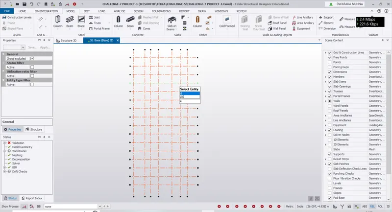
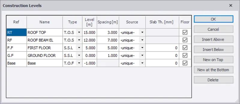
- set the setting to be applied on to the structure or model under the home tab
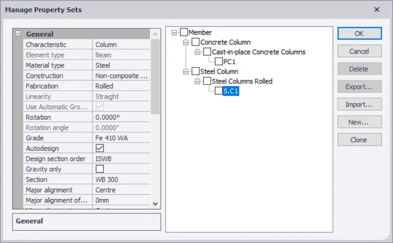
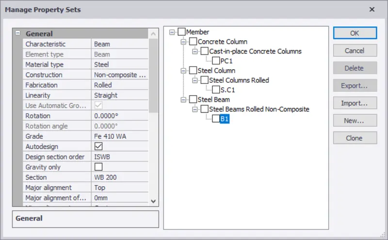
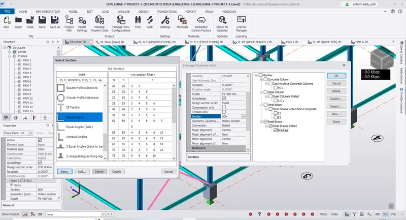
- then goto manage property sets to define the materials and profiles sizes .
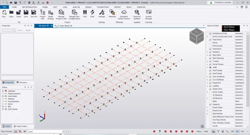
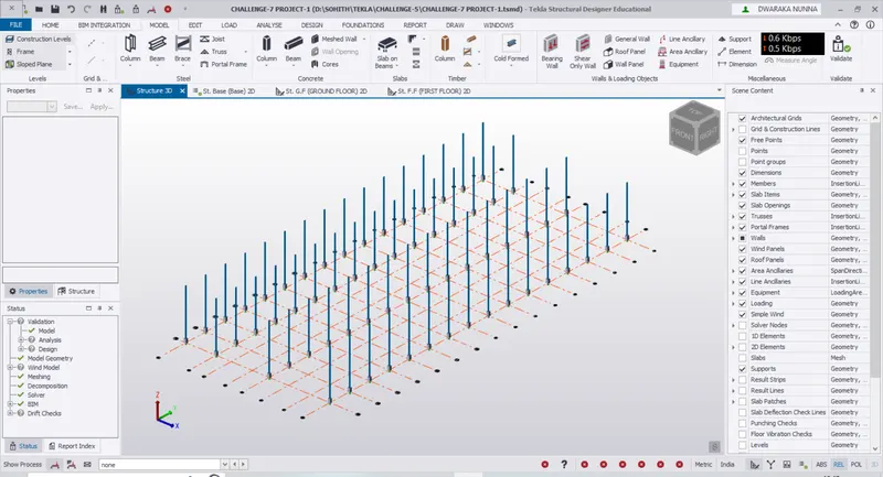
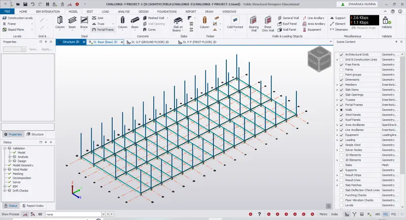
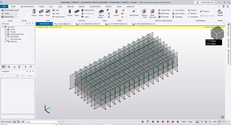
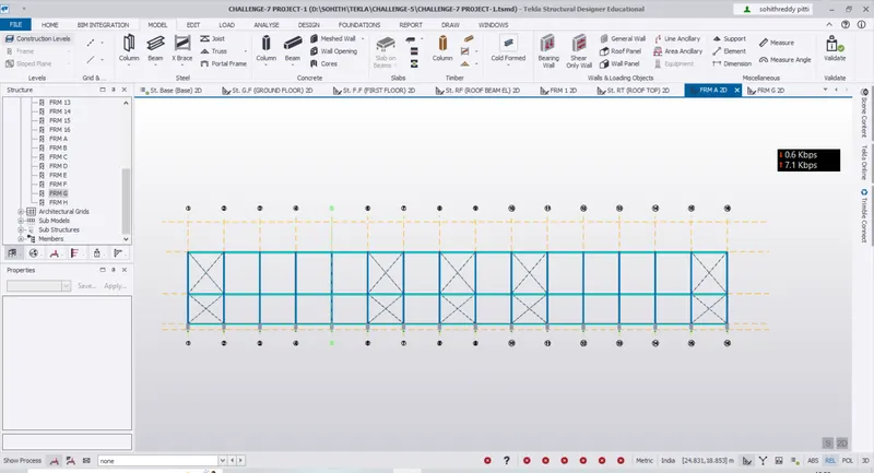
- afterthat model the structure with defined elements the specified sizes of elements.
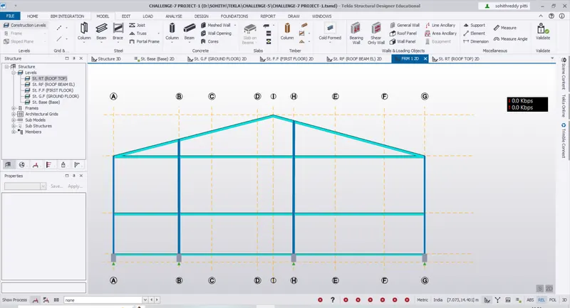
- next we add frames at the each grid to do that choose the frame option under the model tab.
- draw the rafter beam and connect the beam with inclined beams with support to column.
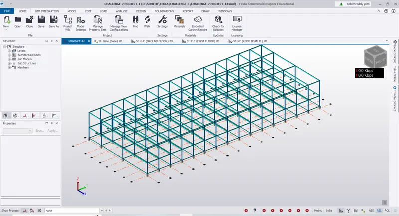
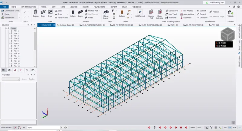
- draw at one frame and copy that to the all points .
- next define the bracing and draw them where to resist heavy loads.
- after that define slab properties and apply them at floor levels.
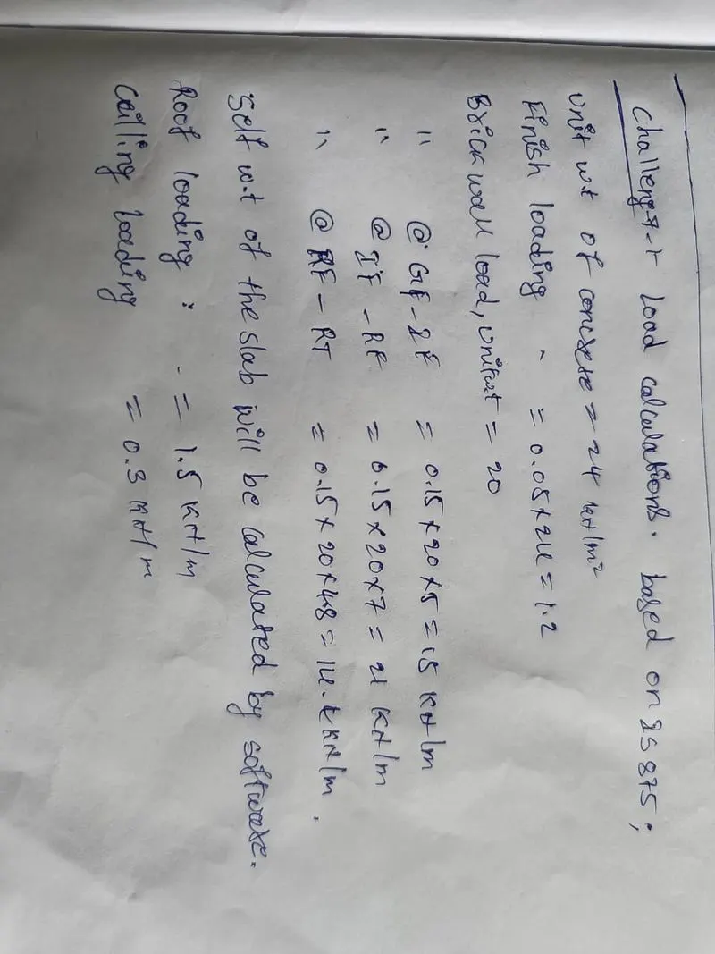
LOAD CALCULATIONS :
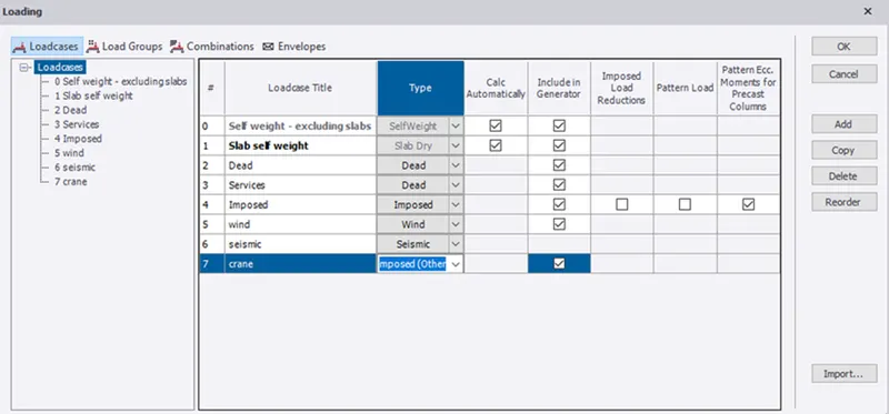
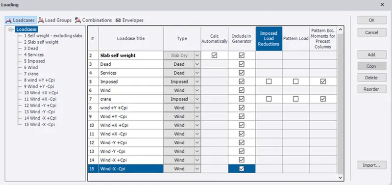
- first go to load cases create the loads according to the data option under the load tab.
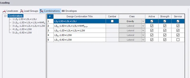
- then go to load combinations generate the load combinations.
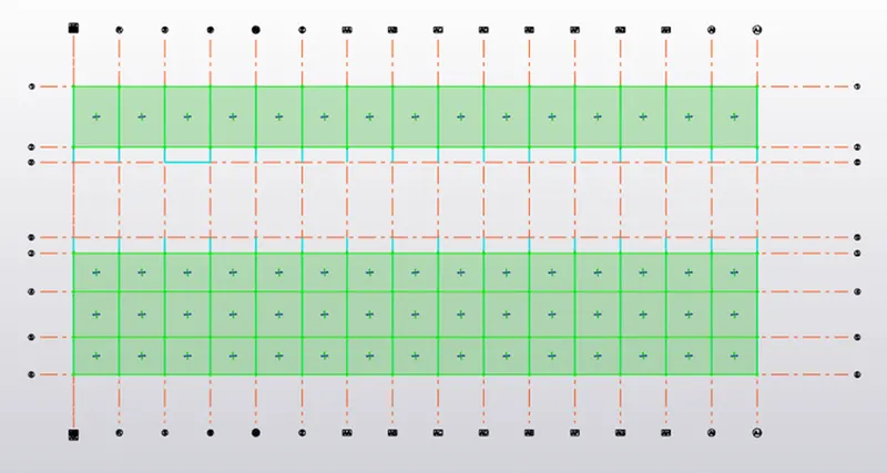
- then apply the loads on the structure by taking area load option under the load tab.
Wind Load Calculation:
Using the IS 875-3: 2015 the wind load acting on both wall and roof was calculated as shown below
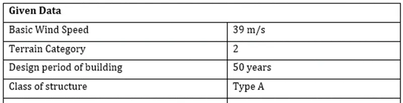
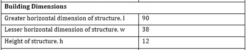
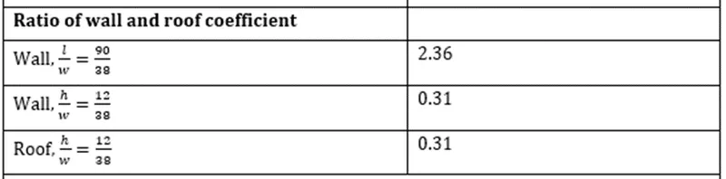
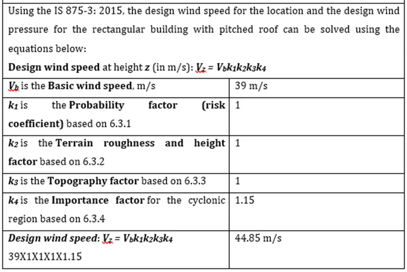
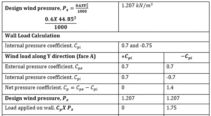
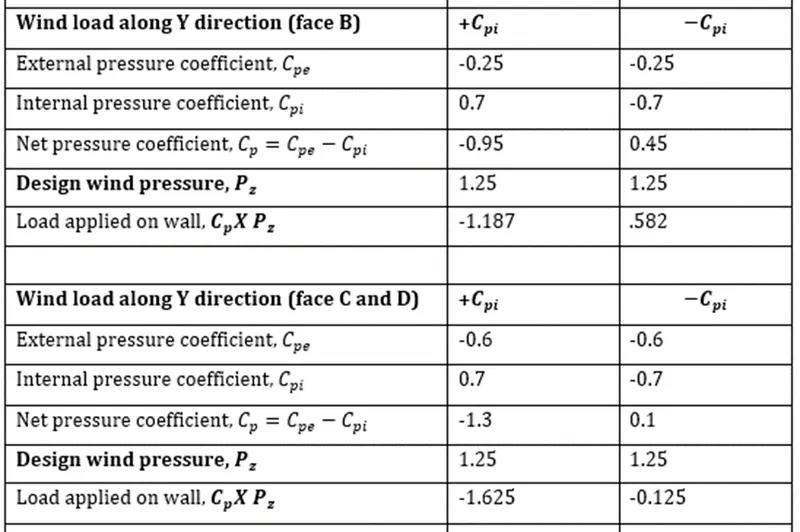
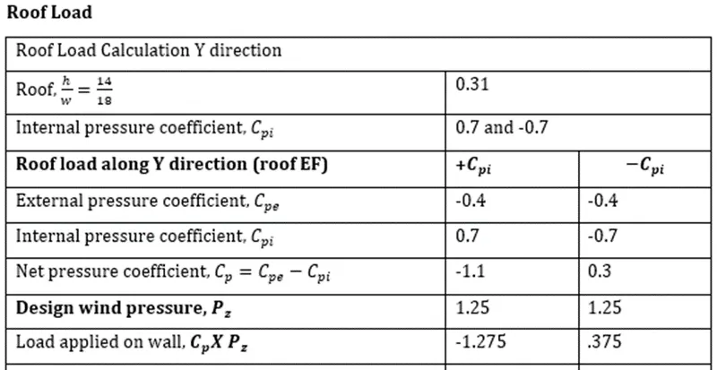
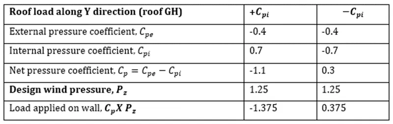
- based on the above data we are going to addwind load in load cases and load combinations .
- based on the value of the load which is negitive or positive that will decide the acting on the face of building.
- so referencing that we create the direction x and y with +cpi abd -cpi load cases.
- then applying loads to the structure.
CRANE LOADING :
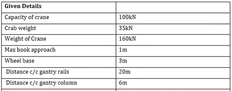
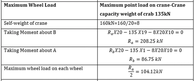
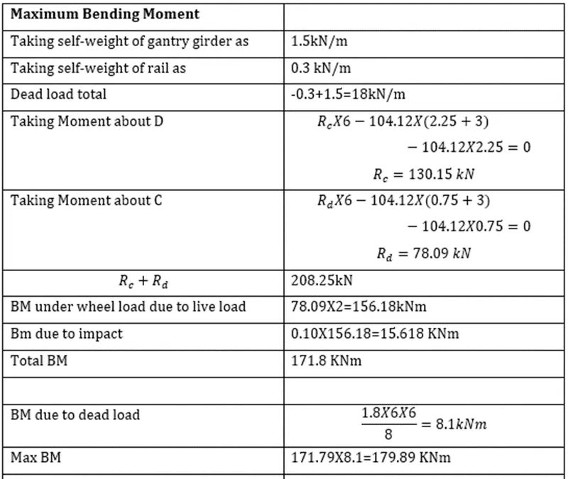
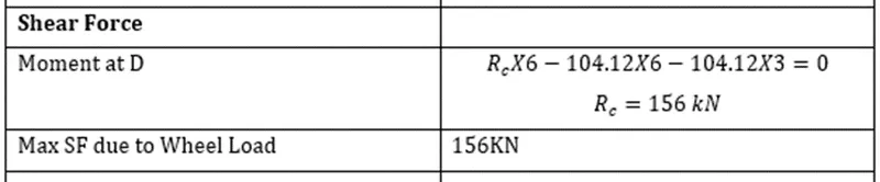
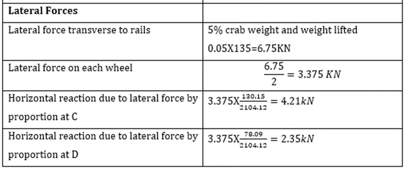
Crane loading was applied to the roof the structure.
Seismic loading was also calculated using the seismic wizard in TSD and after that the model was analyzed (1st order analysis).
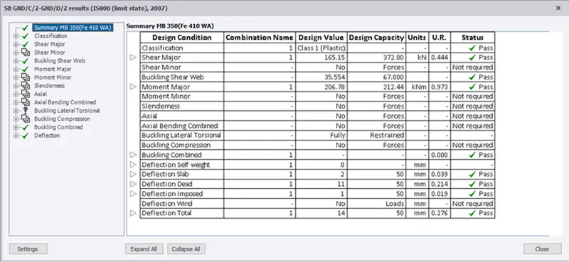
After analysis, all the components was adjusted or resized whenever error occurred
RESULTS:
- The plans were extracted with detail of each member and created in the model.
- Generated errors are corrected
- All the loads are applied to the model.
- Analysis also done to the structure with the applied loads.