Project 1_Analyze and design a steel building to 10T CRANE as per IS standard code using TEKLA STRUCTURAL DESIGNER.
Question-
Analyze and design a steel building to 10T CRANE as per IS standard code in TEKLA STRUCTURAL DESIGNER. Refer the attached plan and elevation. Provide bracings and moment connection for lateral stability.
Consider dead, live, equipment and wind loading. Consider the brick wall loading for 150mm thick and 1.5 KN per sq m for wall and roof cladding.
Assume wind loading basic speed as 39m/s
Report of each member to be generated and extract drawings of structural plans from the software.
Ans=
AIM:- To analyze and design a steel building to 10T CRANE as per IS code in TEKLA STRUCTURAL DESIGNER.
INTRODUCTION:-
Loads cases and load combinations are generated, assigned for the structure using tekla and validation of those loads is an important part of Tekla Structural Designer as it ensures a valid model for the analysis and design routines. Imposed Loads are assigned according to IS 875 Part 2.
PROCEDURE:-
Step-1-
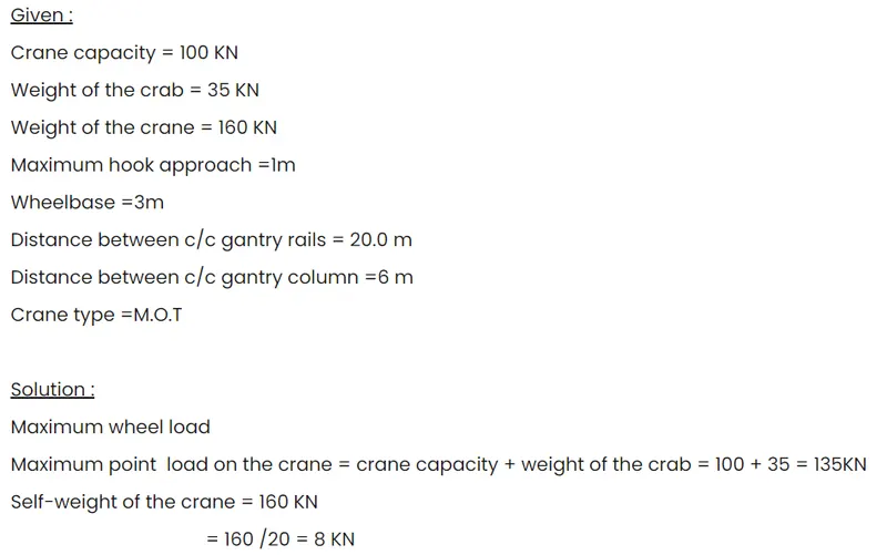
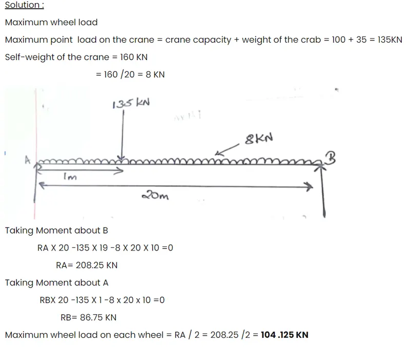
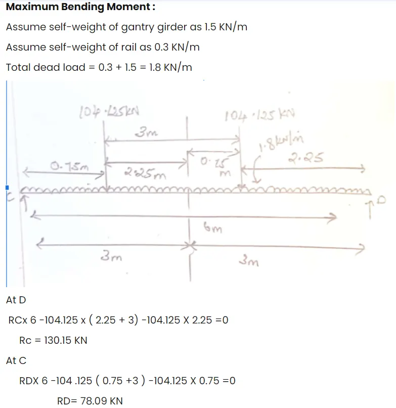
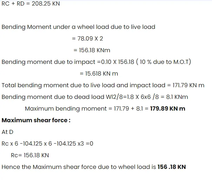
Crane load calculation:-
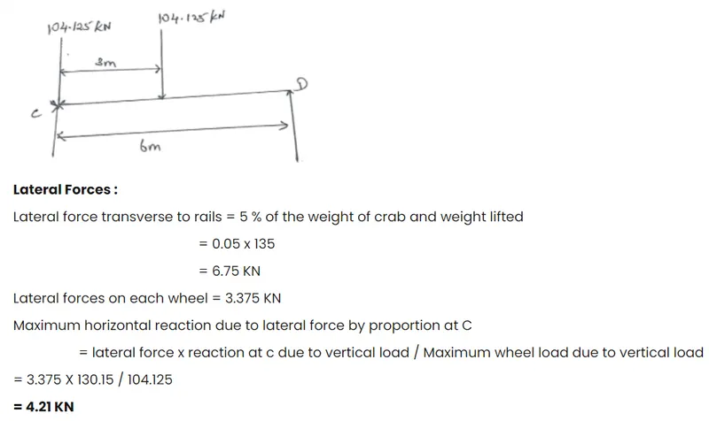
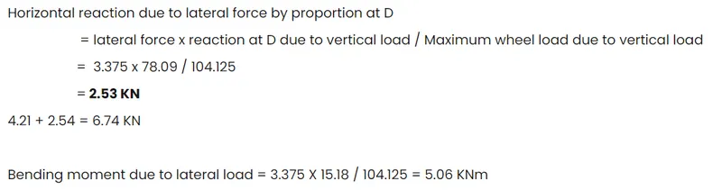
Load calculation:-
Dead Load calculation-
Slab load : model slab in software
Finishes : 50mm x 24 KN/m^3 = 0.05 x 24 = 1.2 KN/m2
Brick wall width = 155mm
Unit weight = 20 KN/m^3
Floor height (Ground floor to First floor) = 5m
Brick wall loading for ground floor = 20 x (150/1000) x 5 = 15 KN/m
Floor height (First floor to roof ) = 7 m
Brick wall loading for first floor = 20 x (150/1000) x 7 = 21 KN/m
Roofing load based on purlin size :1.5KN/m^2
Ceiling loading 0f 0.3KN per sq m
Live loads taken as per IS 875 Part 3
Work areas without machinery/equipments = 2.5KN/m^2
Work areas with machinery/equipments (Heavy) = 10KN/m^2
Staircase : 4KN/m^2
Toilets : 2KN/m^2
Canteen : 3KN/m^2
Store room : 2.4KN/m^2
Conference room : 4KN/m^2
Meeting room : 4KN/m^2
Office room : 4KN/m^2
Manager room : 4KN/m^2
Corridor : 4KN/m^2
Roof access not provided is taken as : 0.75KN/m2
Crane load = 10T
Wind load calculation:-
Wind speed taken as 39m/s
Terrain category is given as 2
Vb = Basic wind speed which is given as 39m/s
Normally basic wind speed is selected from appendix A of code book IS 875 III which is given based on wind speed in various cities
Design wind speed Vz= Vb*K1*K2*K3*K4
Where Vz depends on risk level, terrain roughness, height, size of structure, local topography
K1 = Probability factor
It is taken from table 1 of IS 875 III
Life of structure is taken as 50 yrs and wind speed is given as 39m/s. Based on this K1 =1
K2 = Terrain, height, structure factor which is taken from table 2 = 1.07
K3 = Topography factor which is taken as 1 (θ<3 = 1 and θ>3 = 1 to 1.36)
K4 = Importane factor for cyclonic region K4 is taken as 1.15
Where K4 = 1.3 Structure for post cyclonic importance
= 1.15 Industrial structure
= 1 All other structure
- Design wind speed Vz = Vb x K1 x K2 x K3 x K4 = 39 x 1 x 1.07 x 1 x 1.15 = 47.9895m/s
- Design wind pressure = Pz = 0.6 x Vz^2 = 1330N/m2 = 1.38KN/m2
- length = 90m, Width = 38m, Height = 20.
- L/W = 2.52 and H/W = 0.526
- External pressure coefficients for wall is taken from table 5 IS 875 III(1/2<h/w <3/2)
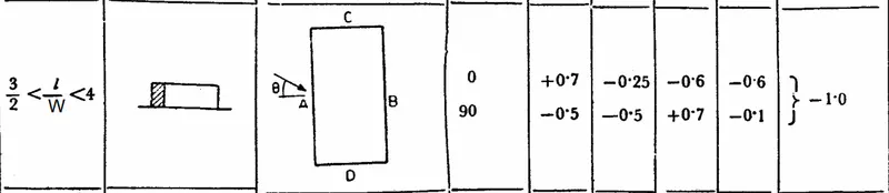
- Roof angle is calculated (18 degree)and based on roof angle external pressure for roof is calculated based on table of IS 875 II

Step-2-
- Open tekla software.
- Click on "Materials" and check for necessary materials and reinforcement available for structure, Example M30, Fe500, sizes of bars etc.
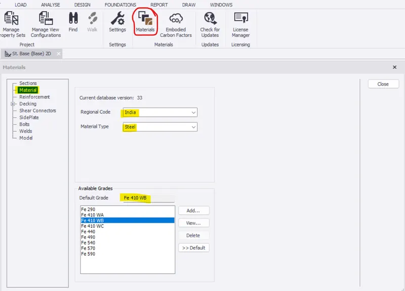
- Similarly check settings for Design code, Design settings, Scene content etc.

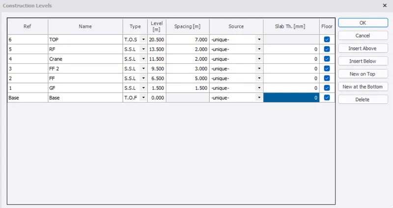
- Now add construction levels as shown below:
- Now add grids
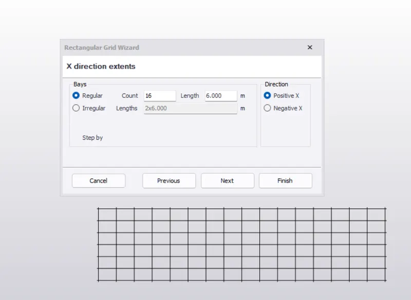
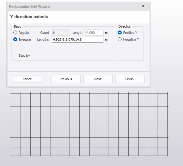
- Go to "Model", In grids select "Rectangular wizard"
- Enter "X" coordinates as shown below
- Enter "Y" coordinated as shown below
Step-3-
- Add Pedestal
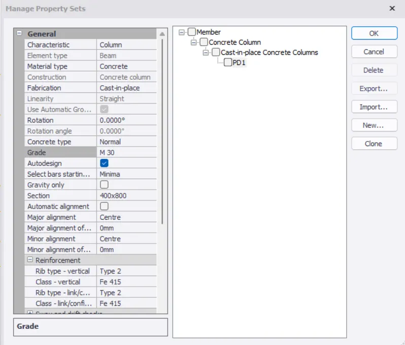
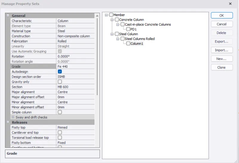
- Select "Manage property sets"
- Click on "Add"
- Select Concrete column
- Change its name to "PD1"
- Change properties of pedestal : Select grade as M30, Change size to 400x800, Set major alignment to Centre
- Click ok
- Go to "Model"
- Select concrete column
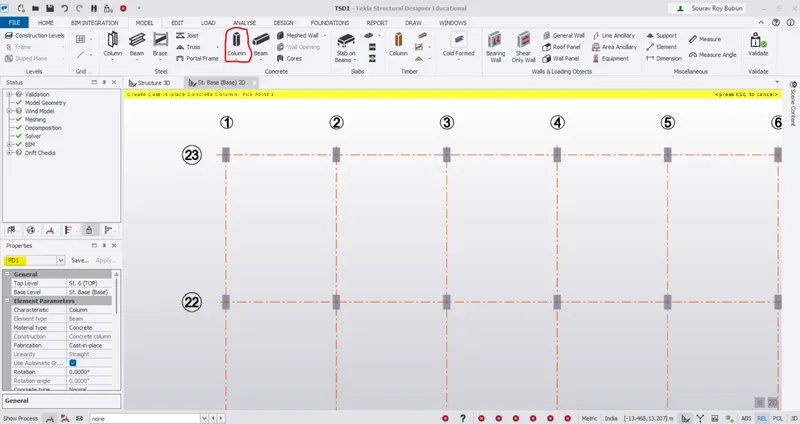
- Add Steel column
- Select "Manage property sets"
- Click on "Add"
- Select Concrete column
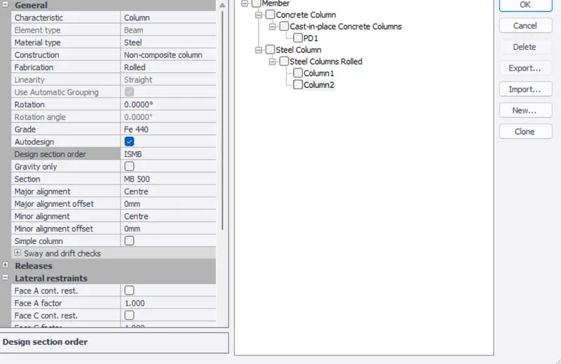
- Change its name to "Column1"
- Change properties of pedestal : Select Section as ISMB600, Set major alignment to Centre and Fixity to Pinned
- Click ok
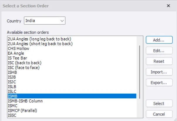
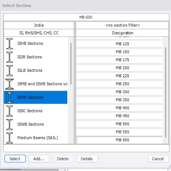
- Similarly create Steel column 2
-
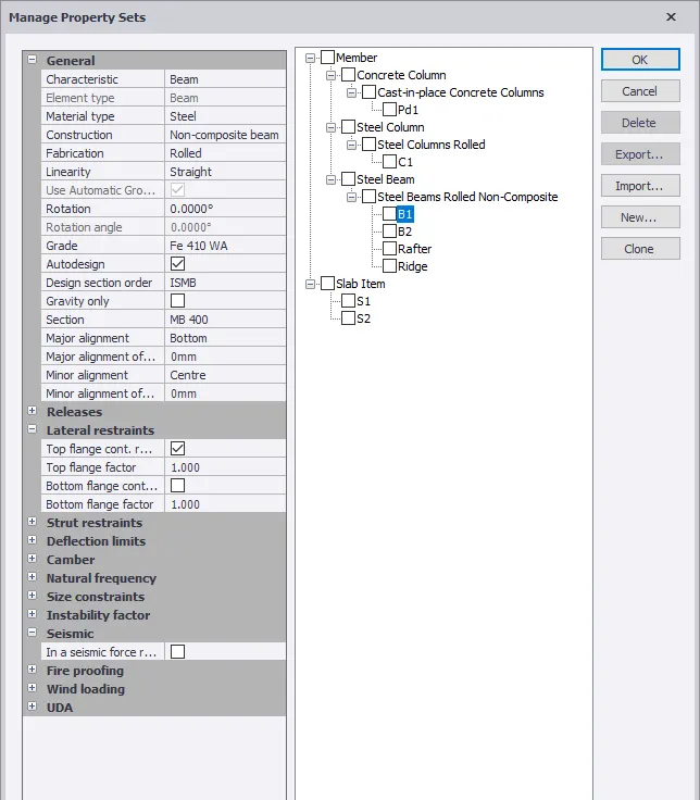
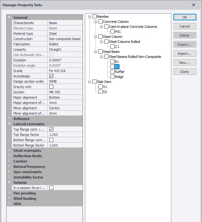
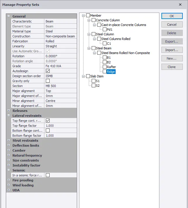
Beam B1 and B2
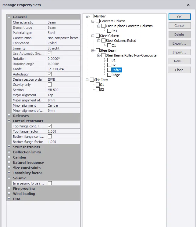
Rafter and Ridge
Step-3-
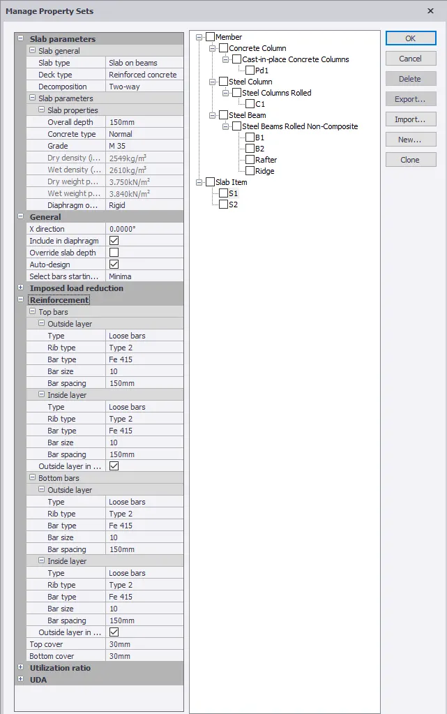
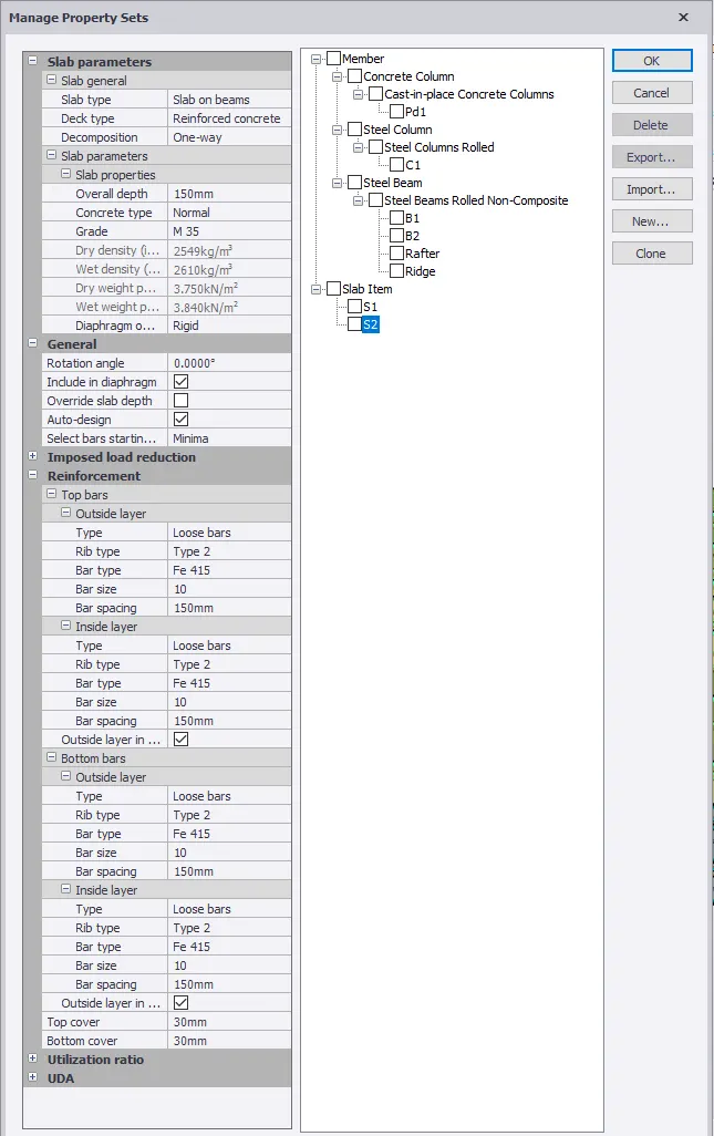
Slab Properties:
S1- Two way
S2- One way
Step-4-
- Add new member : Steel brace
- Assign section as : Equal angle 75x75x8 size and Connection as bolted, Untick : Autodesign
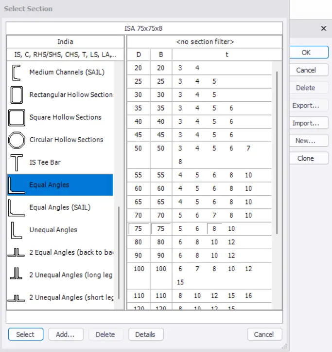
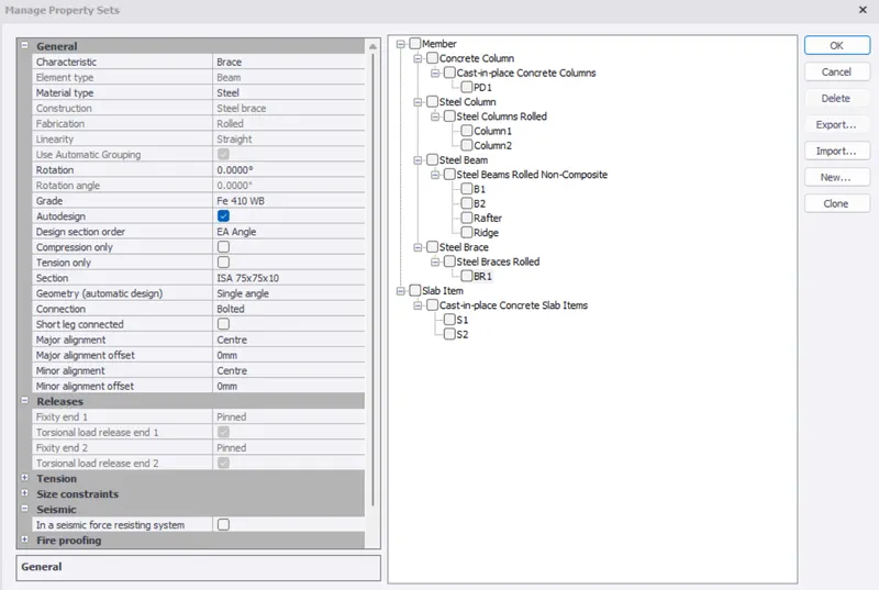
- Select brace - X from model and draw bracings
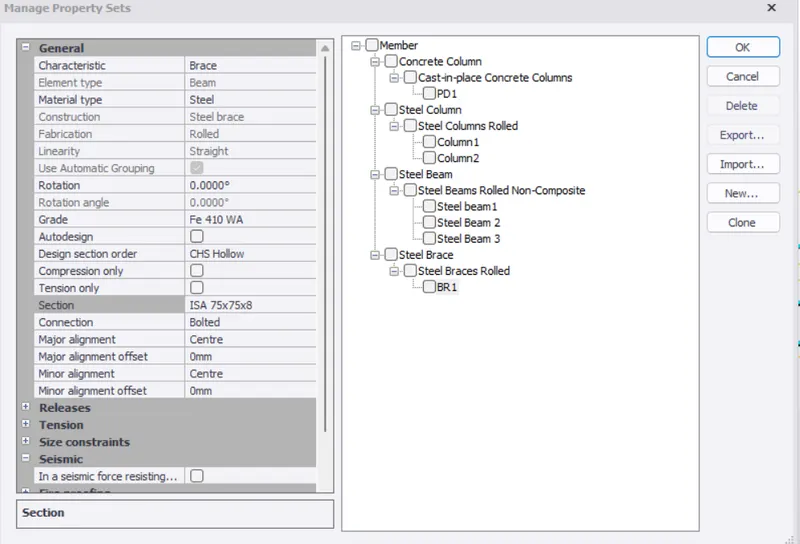
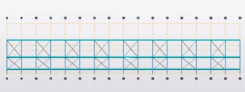
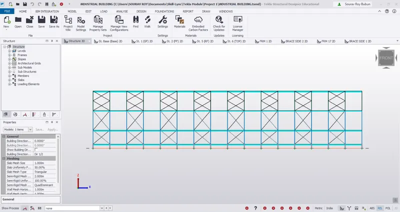
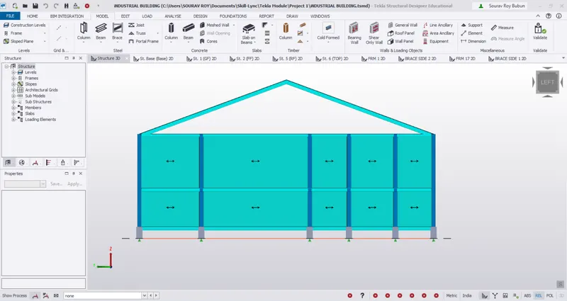
- After assigning the member properties wall and panels along with the bracings are applied.
Wall panels with bracings on Frame A and F
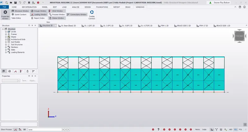
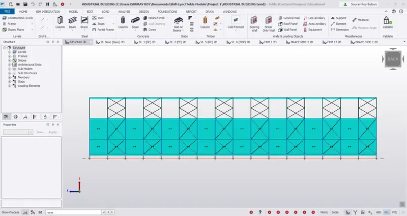
Wall panels with bracings for Frame 1 and 16
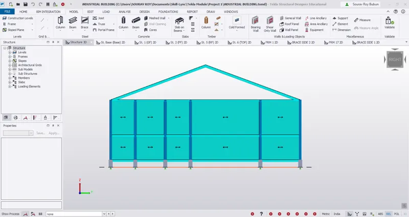
Step-5-
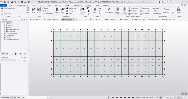
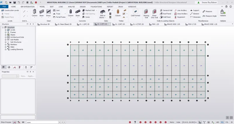
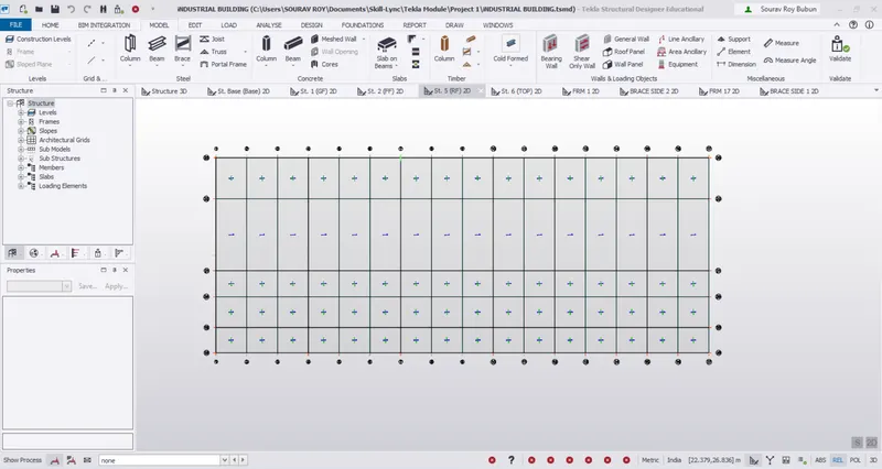
- Now slab S1 and S2 are applied on the:
Ground floor
First floor
Roof beam level
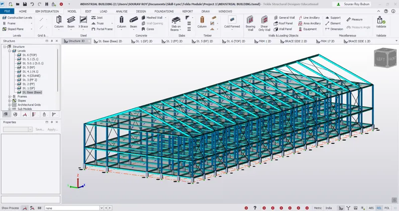
3D view:
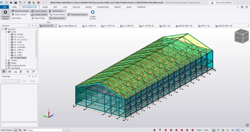
- Model is validated once and combination of loads are defined.
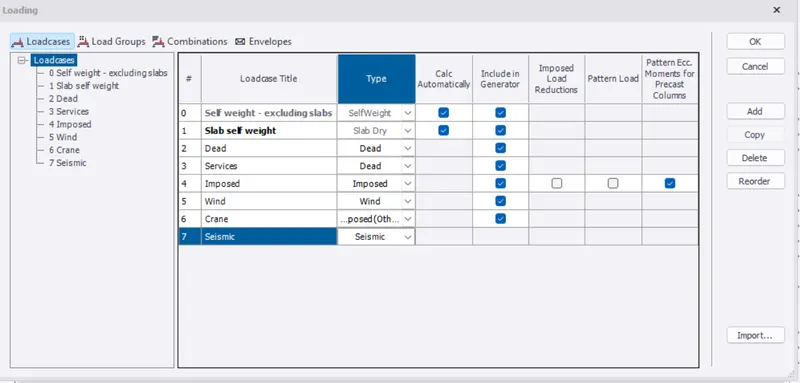
- Select "Load cases" and add load cases
Step-6-
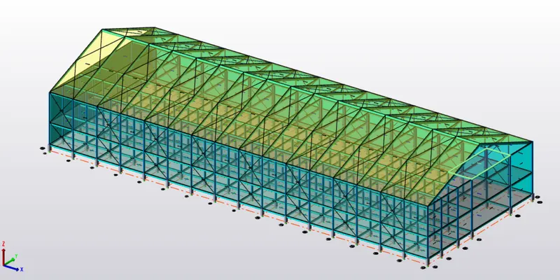
- Add wall panels and roof panels
Step-7-
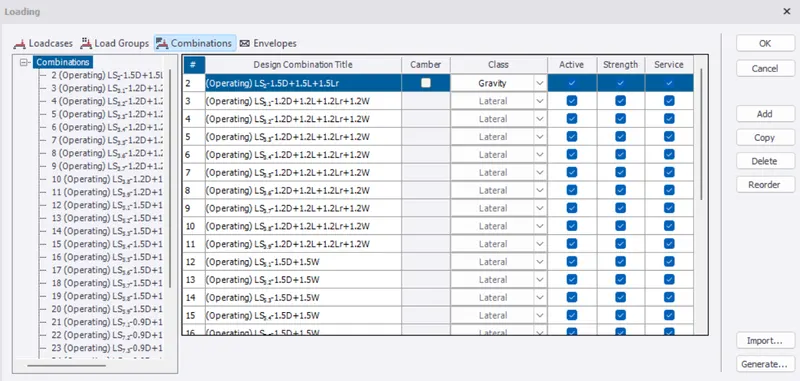
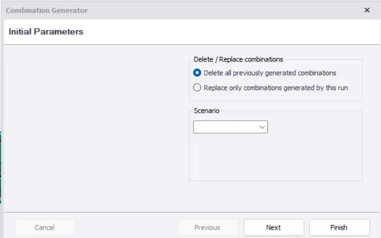
- Generate Load combinations
- Select dead load at the bottom
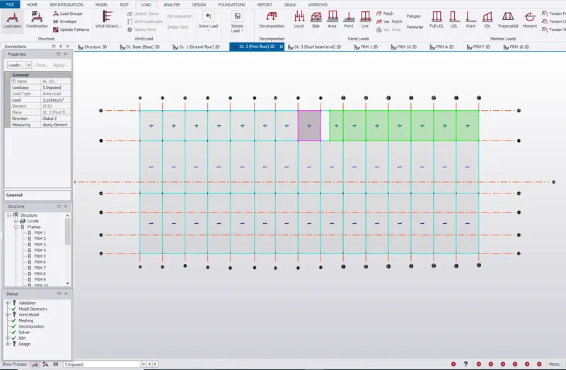
- Select area load = 1.2KN/m2 in ground floor and first floor and apply it
- Select Full udl for brick load = 15 kn/m for ground floor, load of 21.7 for first floor and apply it.
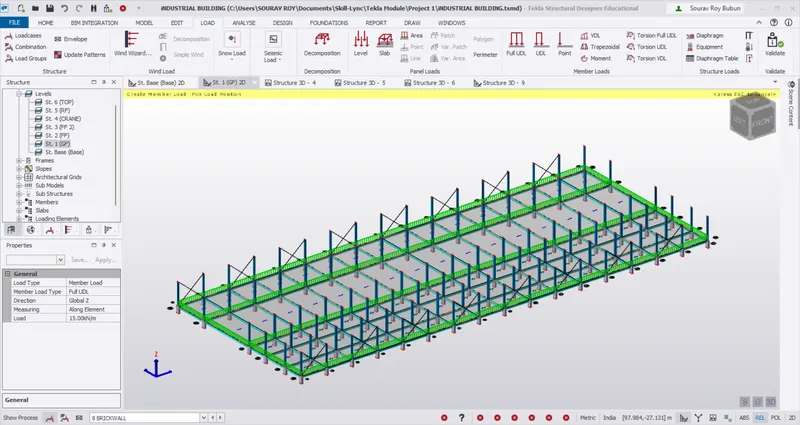
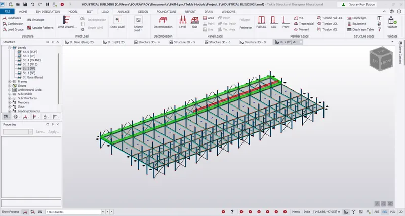
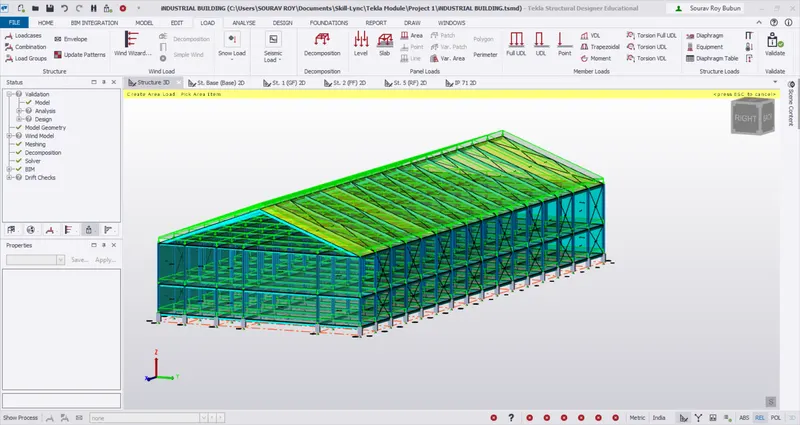
- Apply dead load of 1.5kn/m2 on roof panles
Step-8-
Live load:
Ground Floor Rooms:
- Office= 3 KN/m^2
- Staircase= 5 KN/m^2
- Workshop= 5 KN/m^2
- Meeting room= 5 KN/m^2
- Pantry= 3 KN/m^2
- Flat Roof without access= 0.75 KN/m^2
- Maintenance Yard= 2.5 KN/m^2
- Maintenance Room= 3 KN/m^2
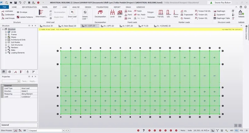
First Floor Rooms:
- Staircase= 5 KN/m^2
- Conference Room = 5 KN/m^2
- Office= 3 KN/m^2
- Toilet= 2 KN/m^2
- Pantry= 3 KN/m^2
Step-9-
- Now apply imposed loads as per IS 875 Part 3 on the floors and roof (0.75KN/m2)
- Go to "crane level"
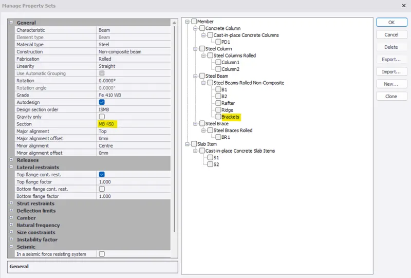
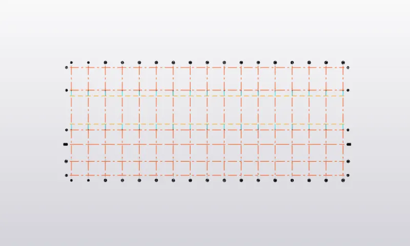
- Draw beams (brackets) as shown below at a distance of 2000mm
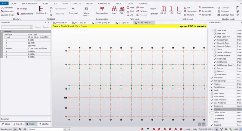
- Select crane load at the bottom
- Now select point load in member load.
- Then select Nodal load.
- In properties enter X= 8KN, Y=22KN, Z=315KN and apply it on brackets
Step-10-
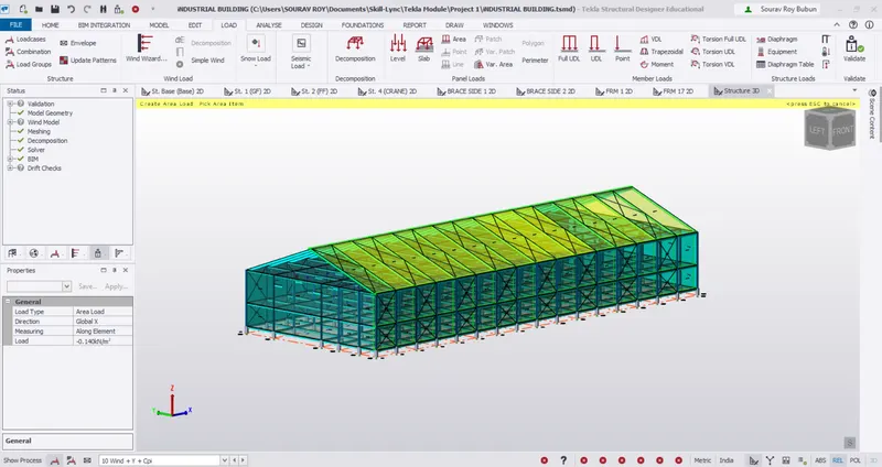
- Now select Load cases for wind panel
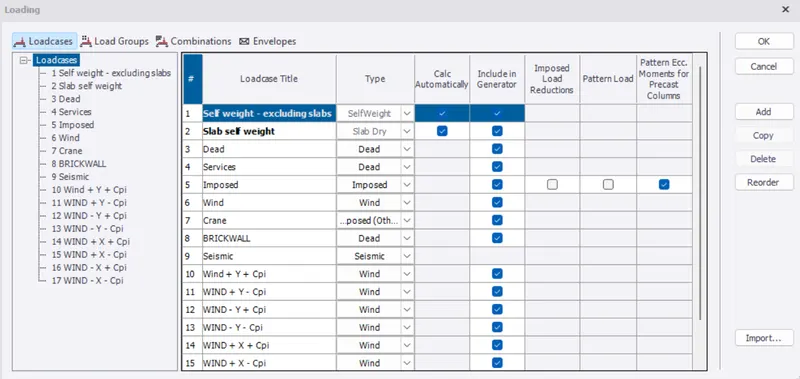
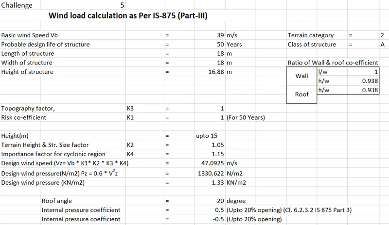
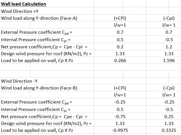
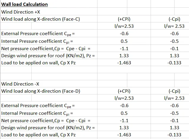
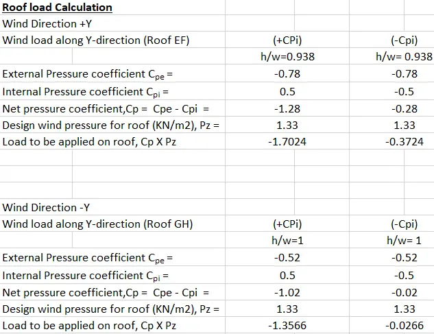
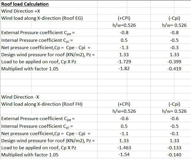
- All these wind load combinations are applied on the model
Step-11-
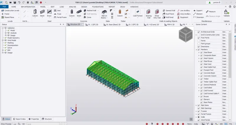
Validated model
Step-12-
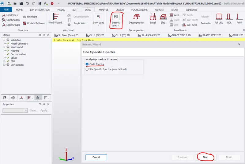
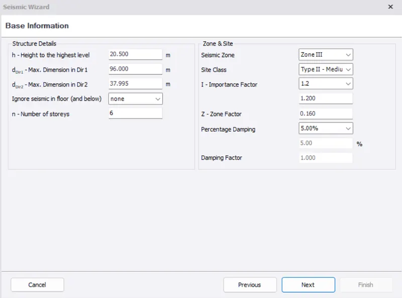
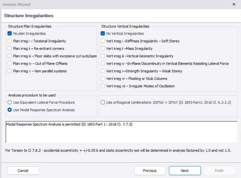
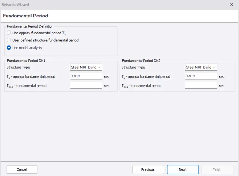
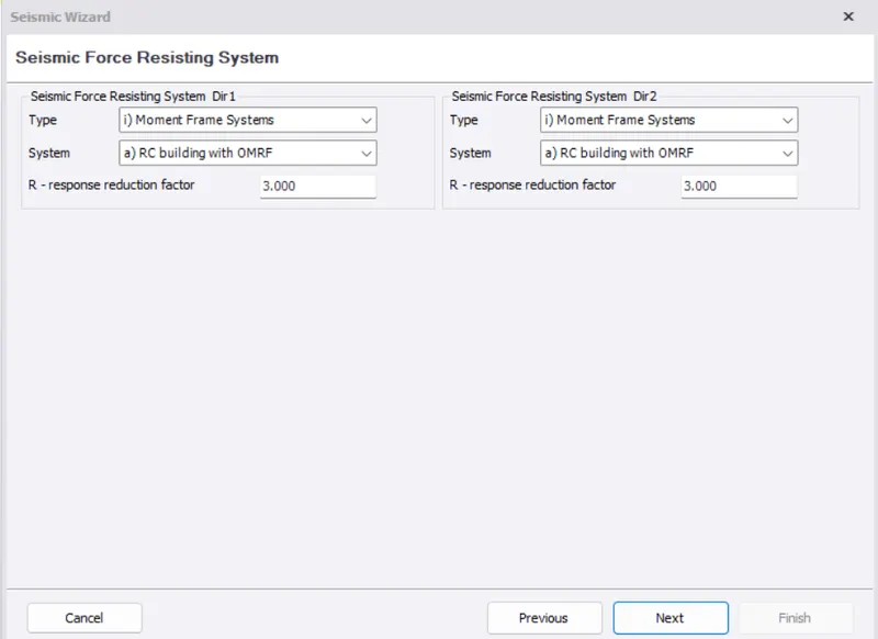
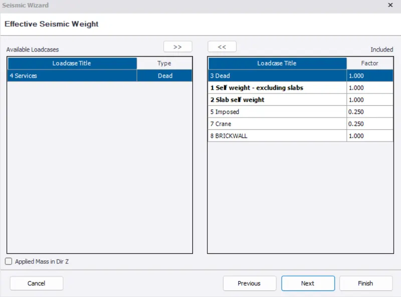
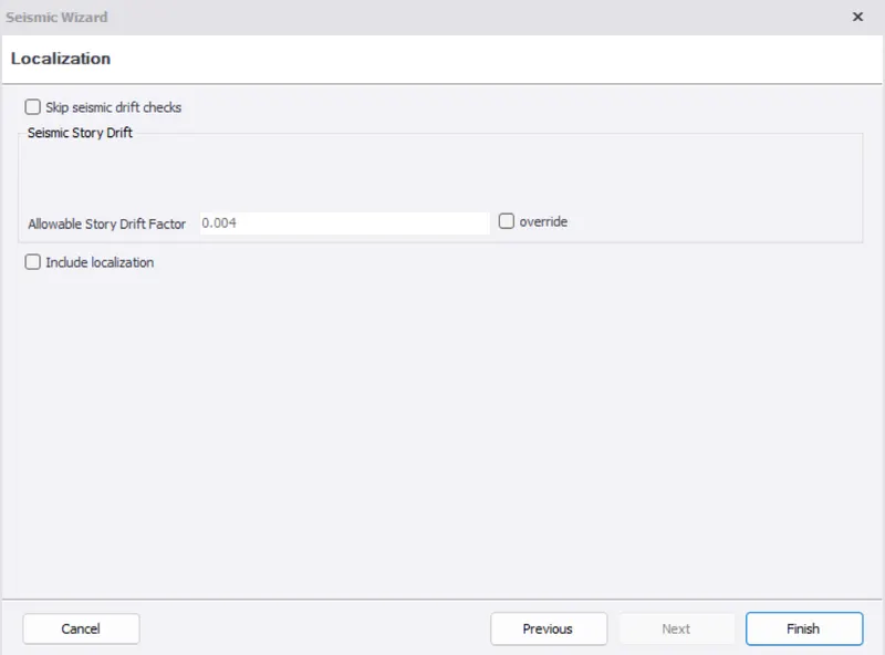
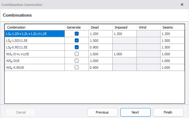
Add seismic parameters
Step-13-
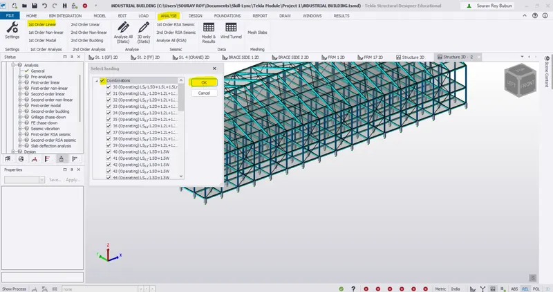
Go to Analysis tab and run the 1st Order linear Analysis
Step-14-
Result view after Analysis
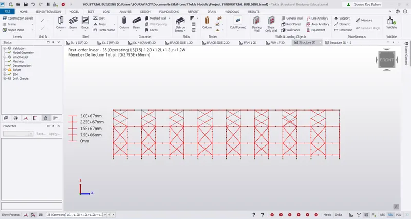
- Click on result view, select deflection
- Select load combination at the bottom
Deflection Result
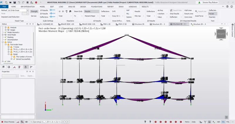
Bending moment Result
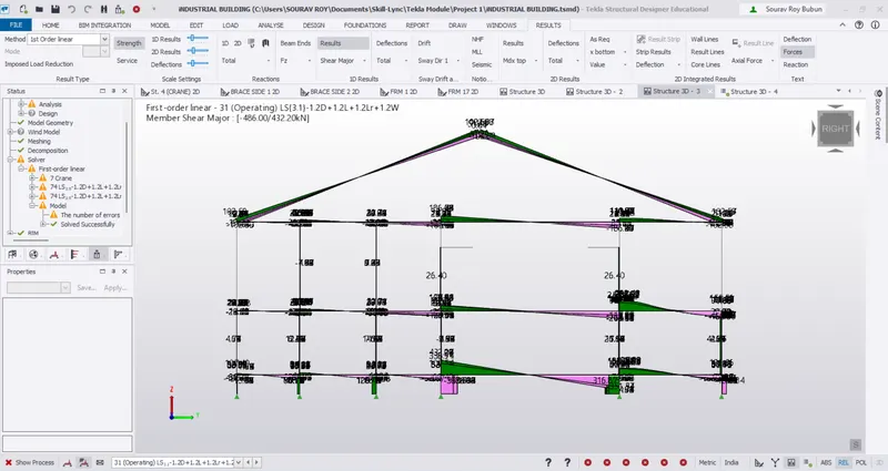
Shear force Result
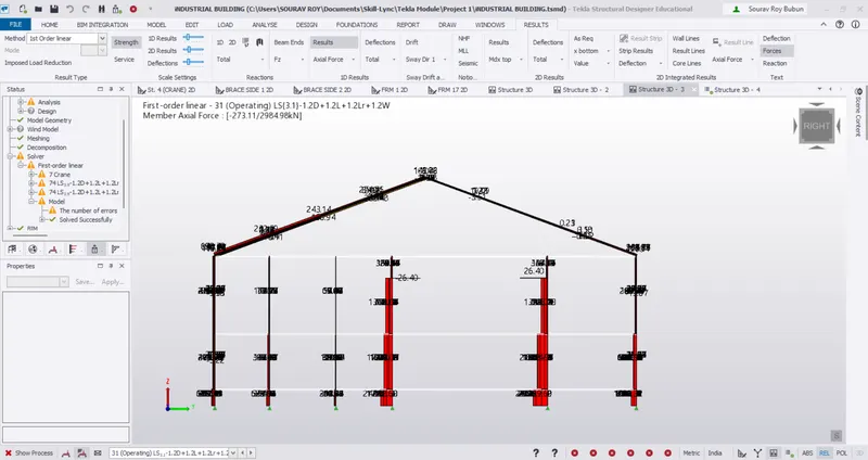
Axial force Result
RESULT:-
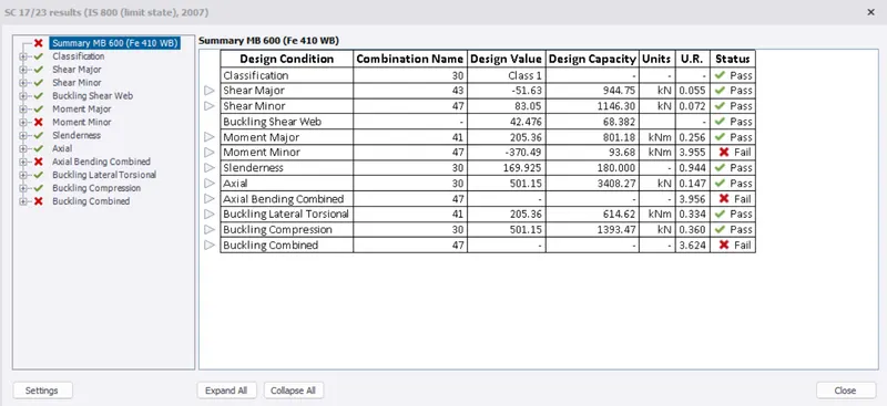
Design result of Column
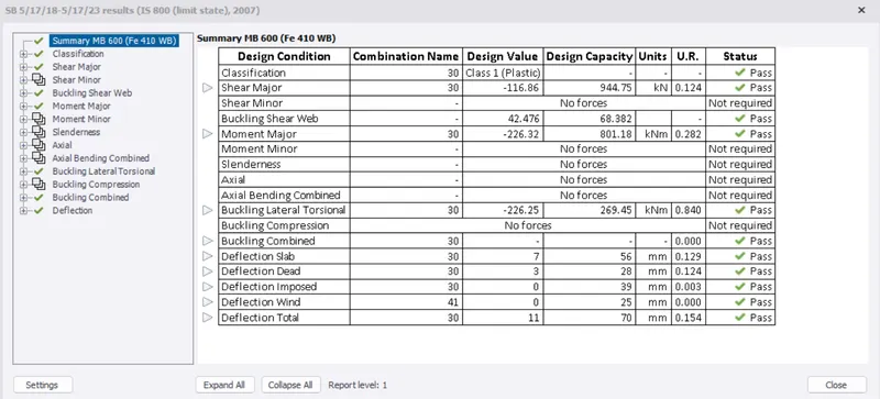
Design Result of Beam
Conclusion:-
Analyze and design a steel building to 10T CRANE as per IS standard code in TEKLA STRUCTURAL DESIGNER has been successfully accomplished and Excel file for wind load coefficient calculation is attached. Eventually, I have attached Tekla Structural Designer file for this Industrial steel building design.