Project 1_Analyze and design a steel building to 10T CRANE as per IS standard code using TEKLA STRUCTURAL DESIGNER.
1)
Aim - To analyze and design a steel building to 10T CRANE as per IS standard code using TEKLA STRUCTURAL DESIGNER.
Introduction -
i) Tekla Structural Designer is an integrated model-based 3D tool for analysis and design
ii) It includes interactive modeling, automated structural analysis and design, drawing, and report creation.
Flowchart in Tekla Structural Designer -
A) Input the geometry and loads -
i) Tekla Strucural Designer has feature that we can import the model date from another files
ii) Or we can create a model as per our requirement
iii) Once the model is created the next step is loading it.
iv) There are various options of loads and load cases are available in Tekla Structural Designer.
v) It also includes a wind load generator available to automatically create wind load cases. You can also generate load combinations automatically.
B) Analyze and design the model -
i) Tekla Structural Designer automatically performs the analyses required to design a member .
ii) This means that analysis and design are combined into a single automated process.
c) Reports -
i) We can create a report of calculations in details.
D) Produce drawings
i) We can produce beam and column detail drawings, and member schedules.
Procedure -
Step 1) Creation of Model
i) Open the assignment which are given to you
ii) Study the drawing before creating the model
iii) Once that is done next step is to Open the Tekla Software
iv) Click on New option
v) Create a Construction level from Cross section view
vi) Model - Construction level - Enter the level details as follows
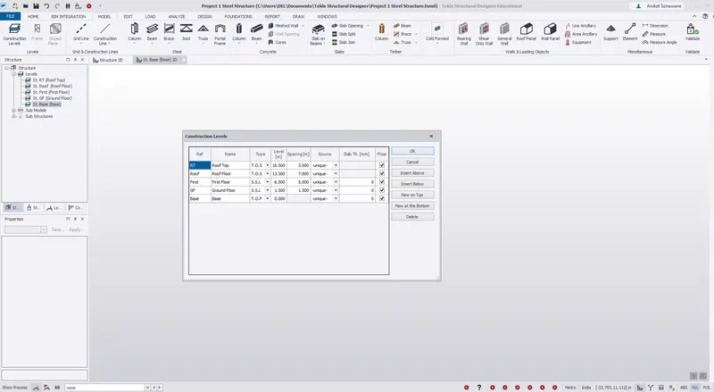
vii) Once the level is defined. Now we have to create a grids
viii) Open the GF level and create a grids
ix) For that Click on Grid Line - Grid line and draw a single grid
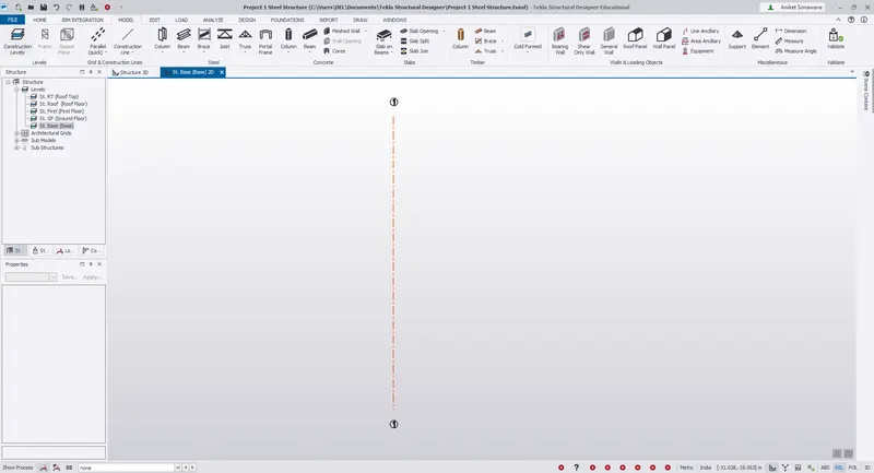
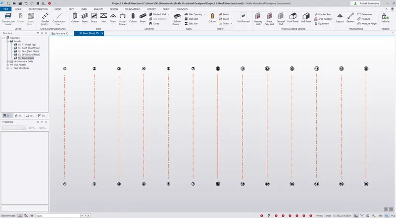
x) Now click on Parallel Quick option to create vertical Grids ( 1 to 16) as per drawings
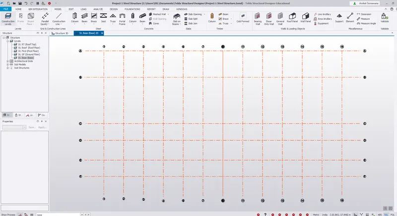
x) Similarly create horizontal Grids
Step 2) Manage Property
i) Now we have to add Pedestal columns at the base level for that click on Manage property sets options and then
manage property sets dialogue box appears.
ii) Click on New - Members and select concrete column.
iii) Rename the column for our own convenience and apply the properties as required on the side.
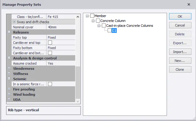
iv) Once property is defined. Click on Model - Column - and assign it as per drawings
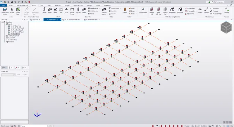
v) In the similar way concrete column was created steel Columns was created.
vi) Now using the Column option assigned the column as per required location
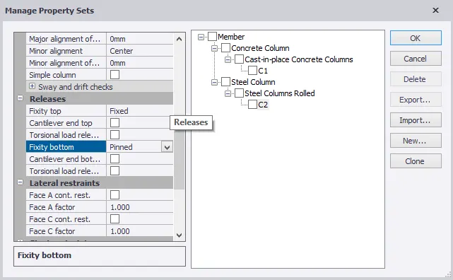
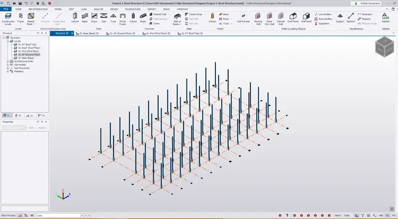
vii) In the similar way steel column was created steel beams was created.
viii) Now using the Beam option assigned the column as per required location
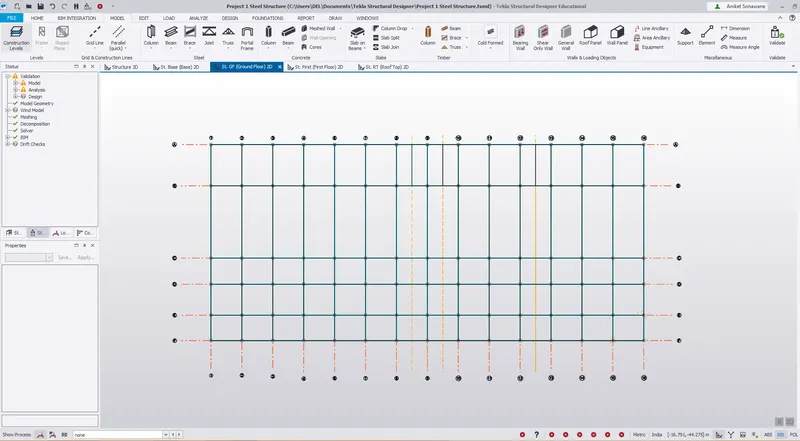
A) Beam layout at Ground Floor
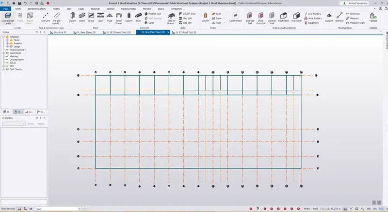
B) Beam layout at First Floor
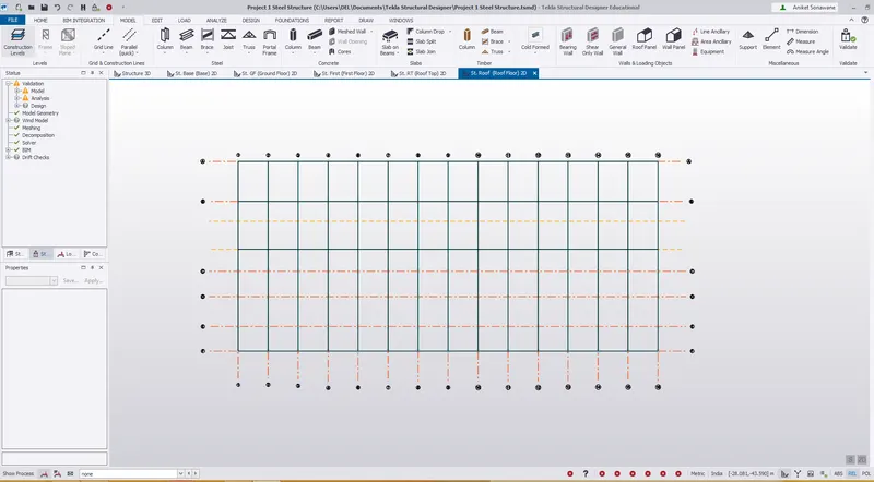
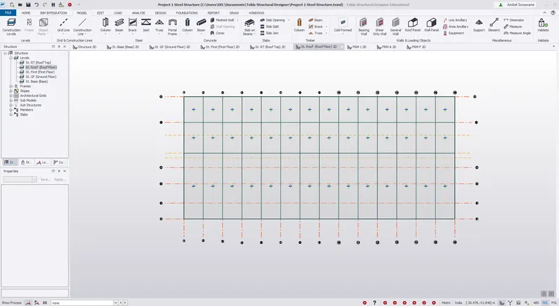
c) Beam layout at Roof Level
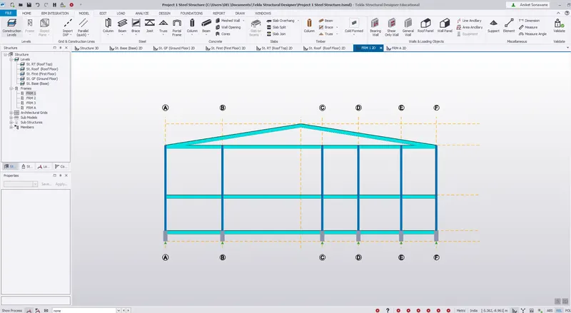
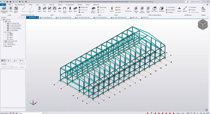
D) Rafter Beam -
i) Rafter beams was designed. Assign B1 prpoerty for trial and error method
ii) Pitch given was 18 degree. So calculate the height by using normal method from Roof level to Roof top i.e 6.173m
E) Steel Bracing
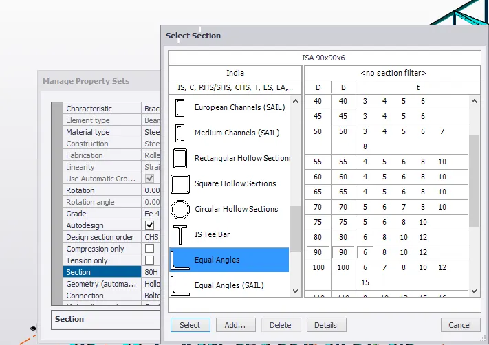
i) After Rafter now we have to add the steel bracings
ii) For that go to Manage Property Set - Click on New - Steel Brace - ISA 90x90x6
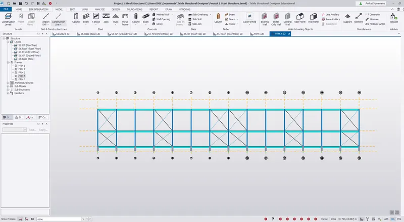
iii) Click on Steel Bracing - X bracing - add the bracings as shown below
iv) Similarly add the bracings on both sides
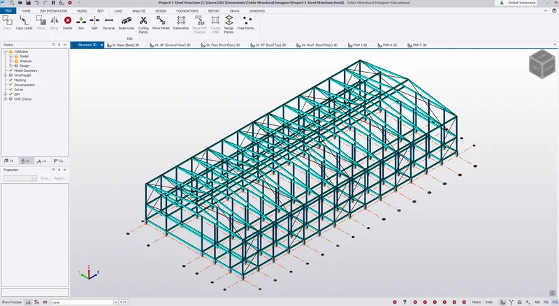
v) Similarly Roof bracing was also added with same property as shown below
F) Slab -
i) Now we have to define Slab
ii) For that click on Manage property sets options and the manage property sets dialogue box appears.
iii) Click on New - Members and - Slabs
iv) Rename the slab and enter the properties such as One way or two way , depth etc.
v) Go to Model - slab on beam - Select all floors the ground floor, first floor and roof level
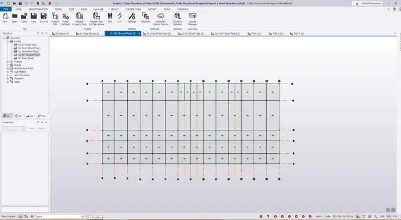
Slab layout at Ground Floor
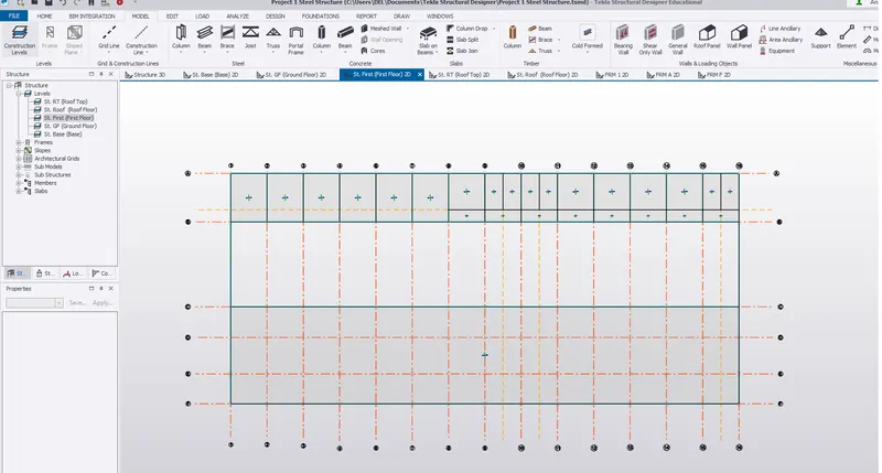
Slab layout at First Floor -
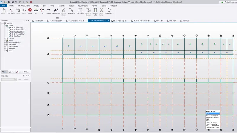
Slab at First Floor Level
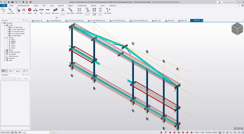
G) Bracket -
i) Bracket is designed to carry the Crane load
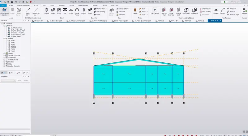
H) Wall Panel and Roof Panel
i) Wall Panel and Roof panel is assigned to distribute the loads to the column uniformly
ii) For that Click on Model Tab - Select Wall Panel - Select the Frames and assigned it as shown below
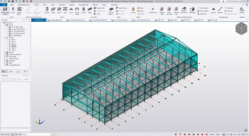
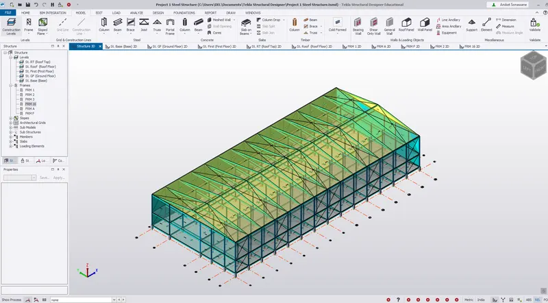
iii) Similalry Roof Panel was also added
Step 3) Load Calculation
1) Dead Load -
|
Load Calculations: |
Based on IS 875 part 1 - Dead load are calculated |
|
Initially based on IS 875 part I, all the dead loads in the steel structure were calculated as follows Unit weight of concrete 24 Finish loading- 0.05x24 = 1.2 Brick wall load, unit weight 20 Brick wall loading (GF-FF) O.15*20*5=15kN/m Brick wall loading (FF-R) 0.15*20*7=21kN/m Brick wall loading (R-RT) 0.15*20*4.8=14.4kN/m Self-weight of the slab is calculated by software itself Roof loading based on purlin size 0.75kN/m^2 Ceiling loading 0.3kn/m |
i) Go to Load tab - Click on Load cases - add the load cases as shown below
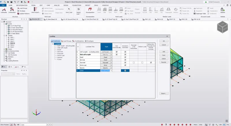
ii) As we are going to apply the dead loads for that select the dead loads option from loadcases
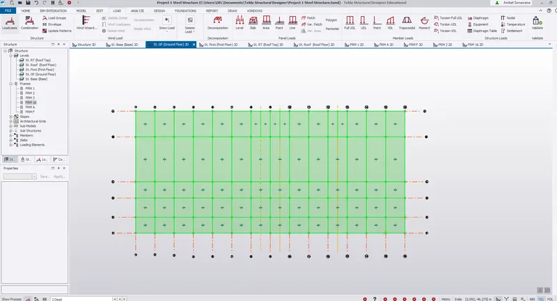
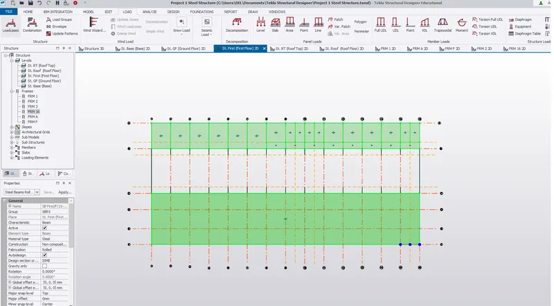
iii) Open a 2D view of ground floor and apply 1.2 kn/m Floor finish load
iv) Click on Load tab - Click Area load
2) Live Load
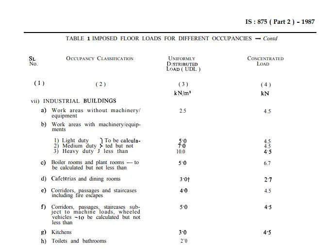
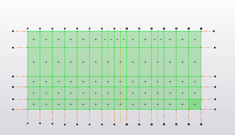
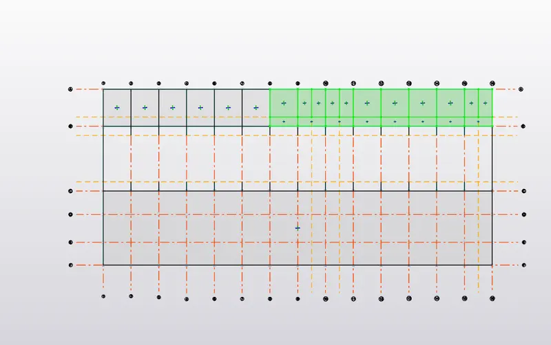
i) Similalrly Live load was also assigned as per IS 875 part 2 - Industrial Building
3) Wind Load Calculation -
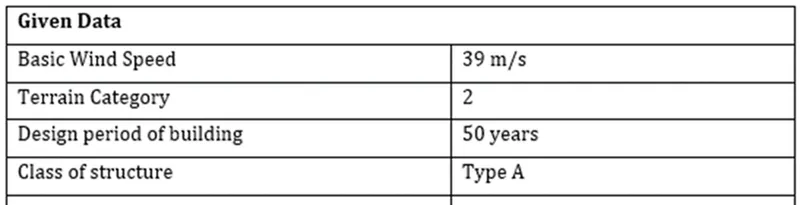
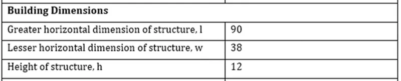
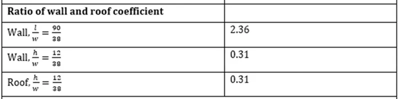
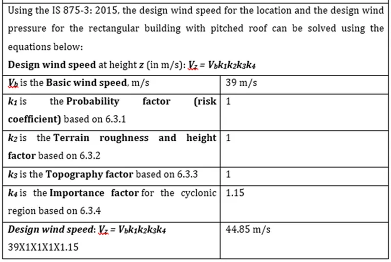
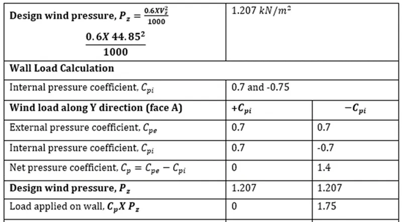
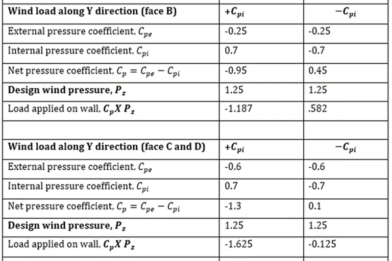
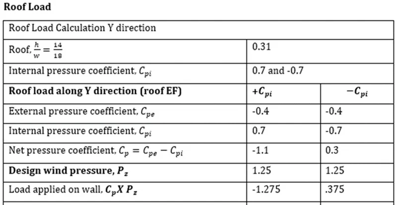
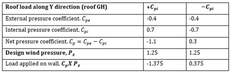
i) As we are applying the wind loads manually.
ii)For that we have to create the new wind load cases by clicking on add option and rename them as shown below
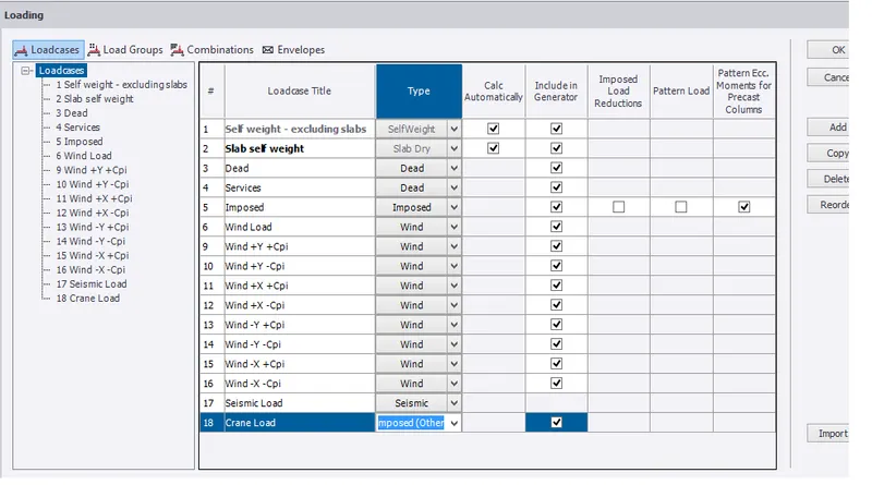
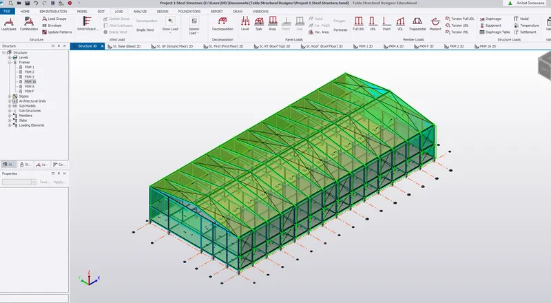
Load has been applied to all the frames as shown below
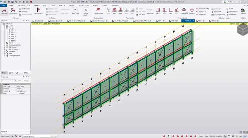
4) Application of Brick Wall loading -
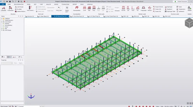
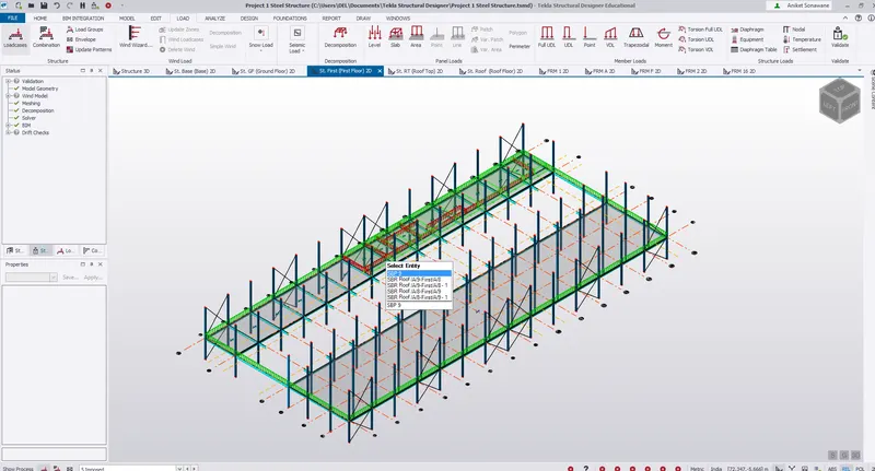
i) As we have already calculate the brick wall load
ii) Go to Load tab - Select Full UDL and apply as shown below
A) Brick wall loading at Ground Floor
B) Brick wall loading at First Floor -
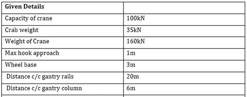
5) Crane Loading -
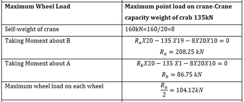
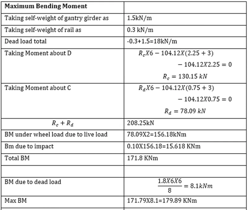
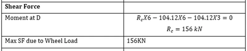
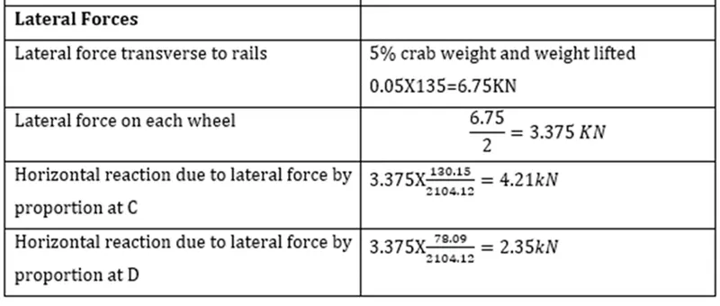
6) Seismic Loading
i) To apply seismic loading
ii) Go to Load tab - Seismic Load - Seismic Wizard
iii) Following Dialog box will appear
iv) Enter the data as follows
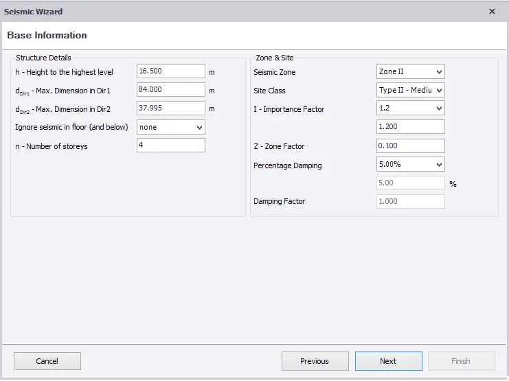
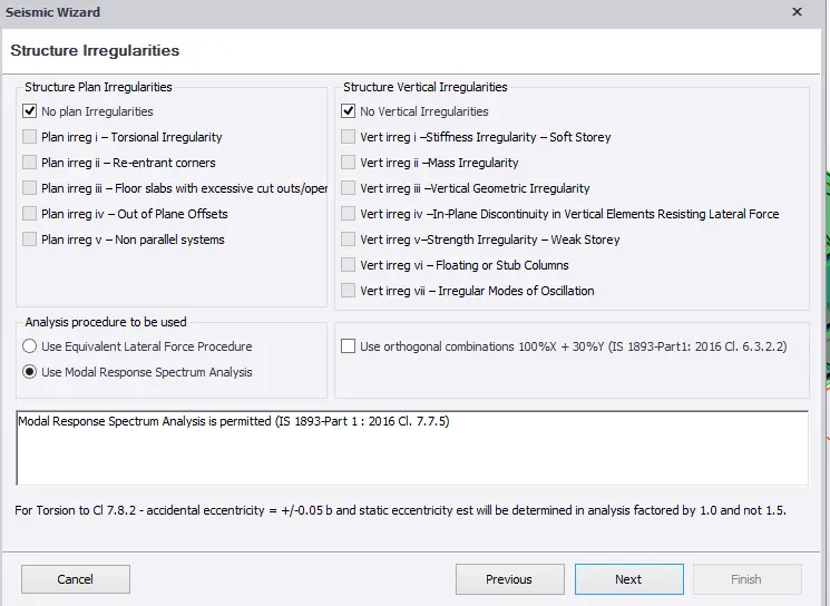
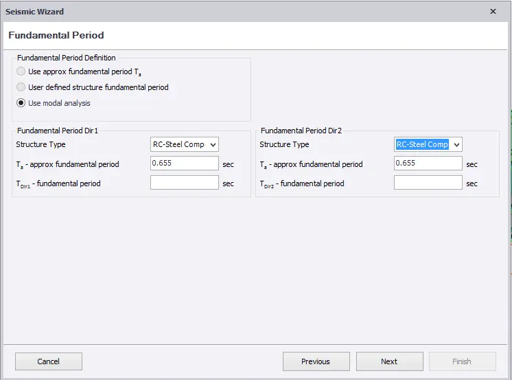
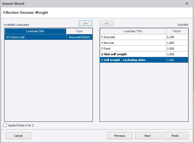
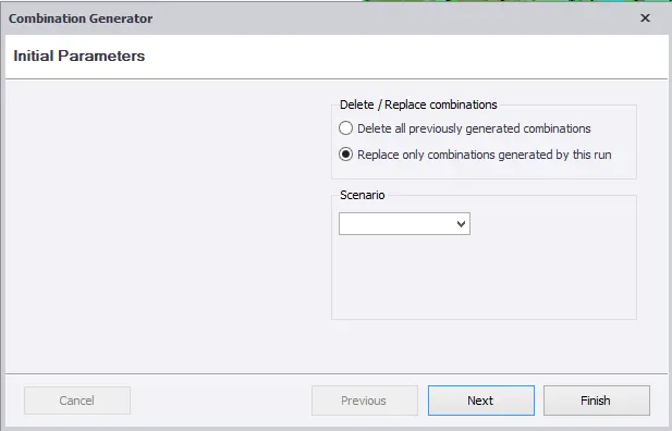
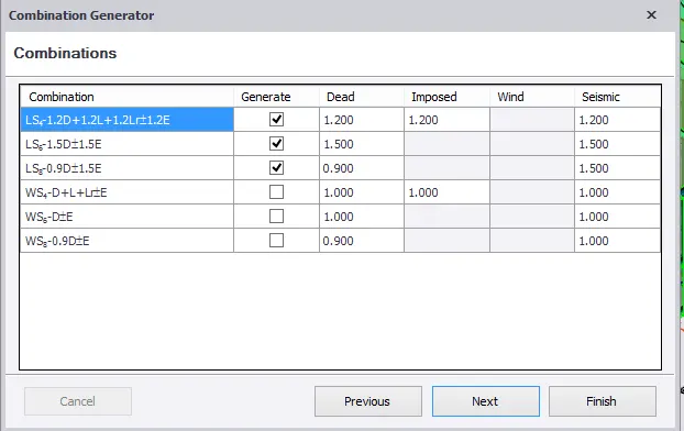
Load Combination are genertaed as per IS 800:2007
Step 5) Analysis
i) Loading process is completed now we can analyze the structure
ii) But before that Validate the model to check the any geometric error
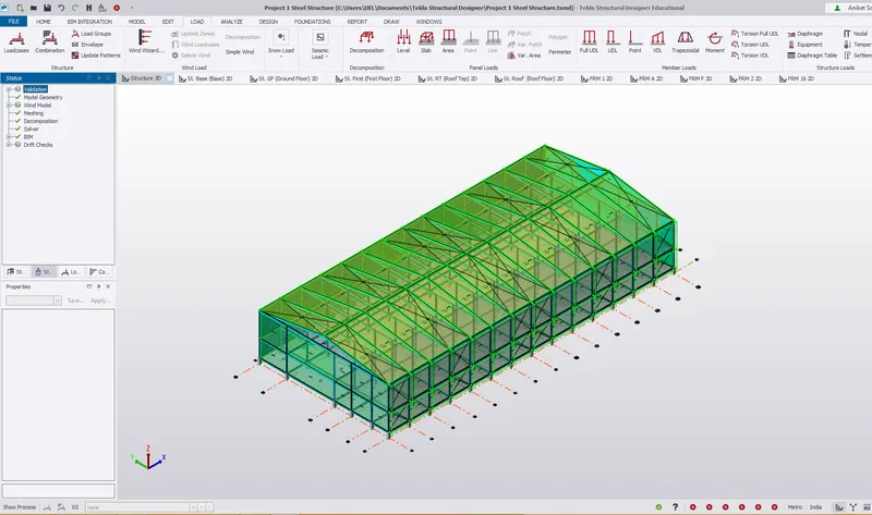
iii) As there is no error we can analyze the structure
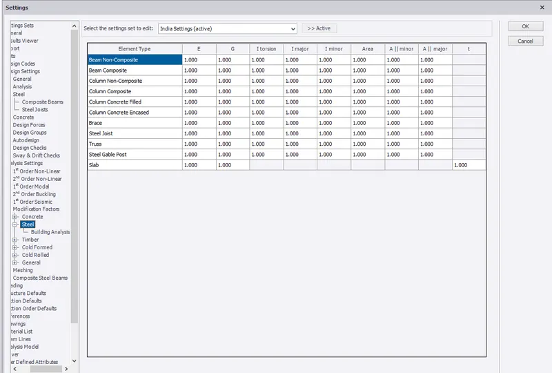
iv) Just check the Modification setting
v) Now Click on 1st Order Linera Analysis
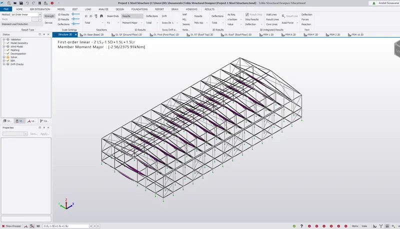
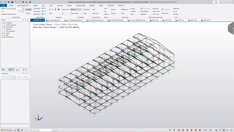
vi) To view the Bending moment , Shear Force
vii) Click on Result View
A) BM in Major direction
B) Shear Force
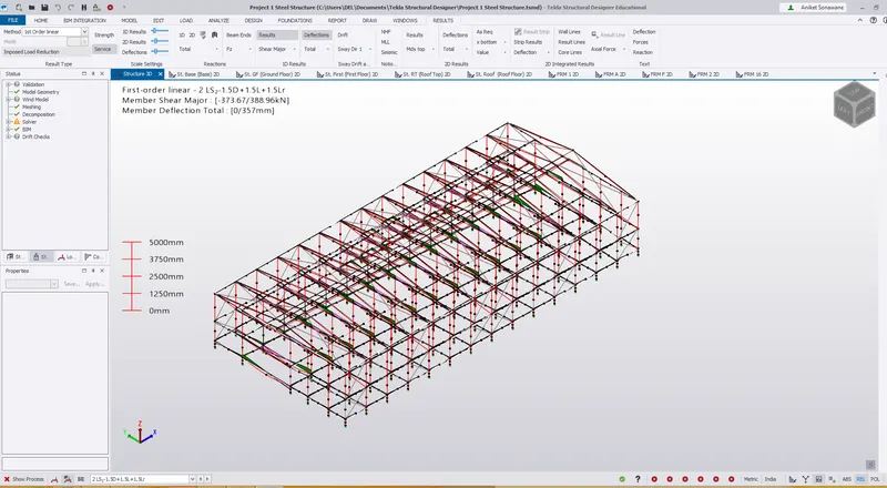
C) Deflection
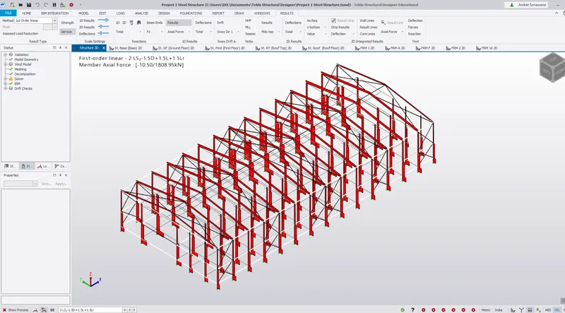
D) Axial Force
Step 6) Design
i) To check the Design of member
ii) Go to frame A
iii) Select the Column and Right Click on it - And Check the member if it is passed or failed
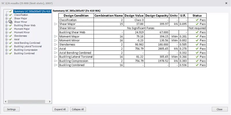
iv) As we can see that Column is passed for given section
v) IF we want we can optimize the structure later .
vi) Similarly for Beam also we can check the member as shown below
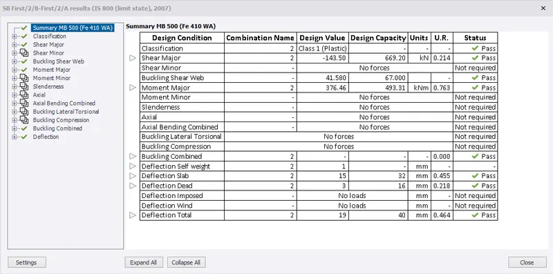
vii) As all members are passed and if members are failing then it is resized
Results -
i) A model was designed in TSD with given plan
ii) All loads were calculated and applied on structure
iii) Analysis were carried out and members are redesigned