Project 1
Aim of The Project : To Model & Analyse the Bridge Section for different Loading Conditions such as - IRS Loads, Wind Loads, Seismic Load & Earth Pressure Load and Location of the Bridge is Stated near Ahmedabad, in Staad Pro and Brielfy Identify The Displacement, Bending Moments, Shear Forces & Plate Stresses Developed on the Structure while subjecting to different Loading Conditions.
Introduction : As we Know Staad Pro is Desinged and Maintained by Bentley Systems Software Company, Staad Pro is used for Structural Analysis and Design Purposes, As we are proposing the structure of 12 m width and 24 m Span Length having pier and abutment height of 8m, The structure having the wall type abutments for earth pressure calculations, we have to analyse the structure for Pipe Loading and briefly describe the analysis results.
Calculations :
Wind Load Calculation
Design Wind Speed Vz = Vb x k1 x k2 x k3 x k4
K1 = Probabilty Factor
K2 = Height Factor
K3 = Topography Factor
K4 = Importance Factor
For Vb Refer IS 875 (Part 3) 2015 Annexure A Clause 6.2, As We Can see Ahmedabad has Vb value of 39
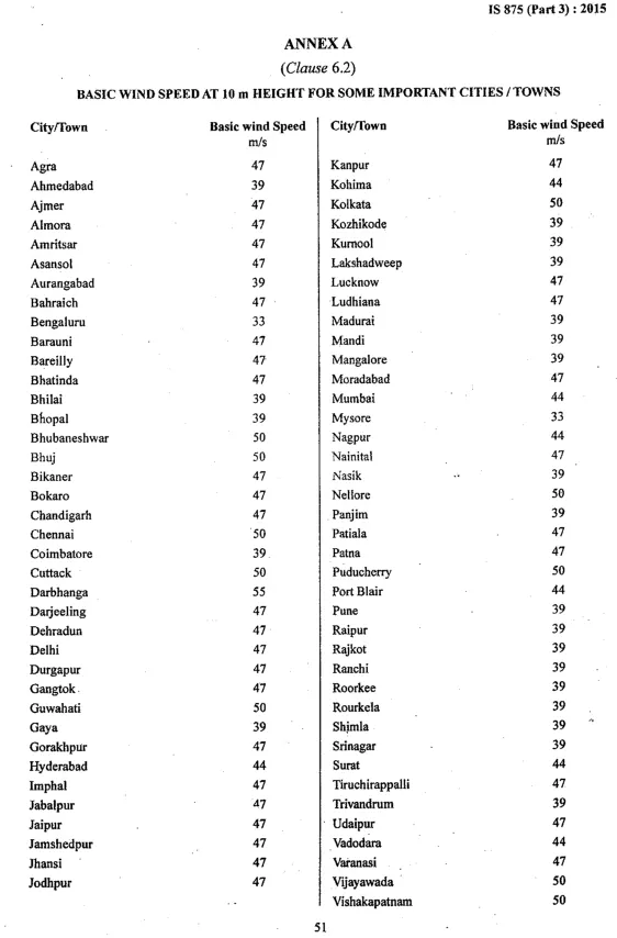
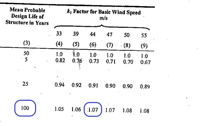
K1 - Probablity Factor Refer IS 875 (Part 3) 2015 Clause 6.3.1, we have to select 100 Years Design Life and For 39 m/s in Mumbai we have to select 1.06 for K1
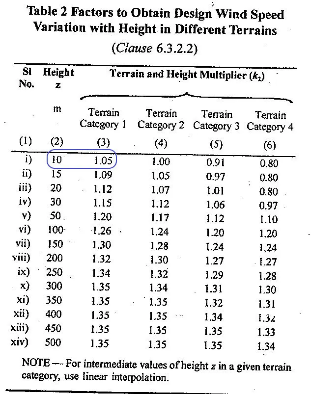
K2 - Height Factor Refer IS 875 (Part 3) 2015 Clause 6.3.2.2 Table 2, As We can see The Structure have a Obstruction Height of 10m and it Belongs to Category 1 we have to select 1.05 for K2
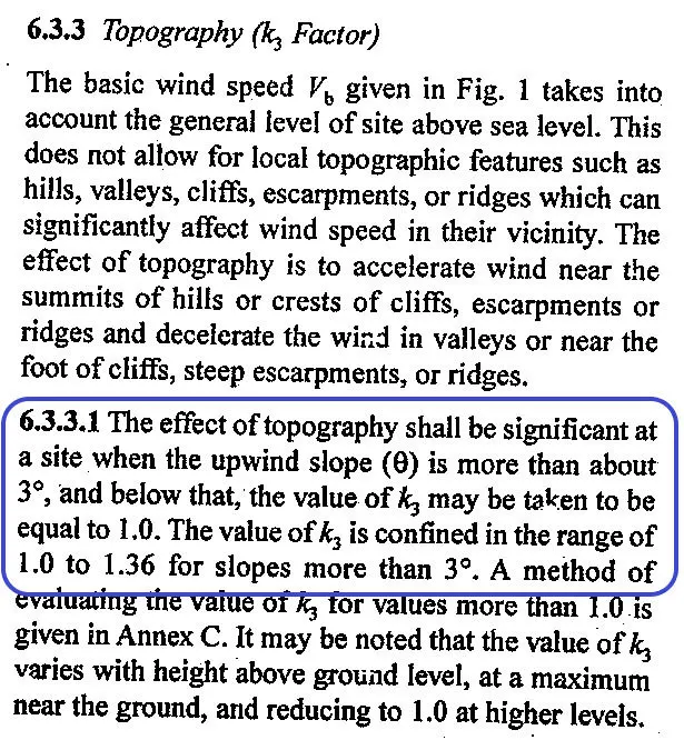
K3 - Topography Factor Refer IS 875 (Part 3) 2015 Clause 6.3.3.1 Paragraph, Select 1.0 for K3.
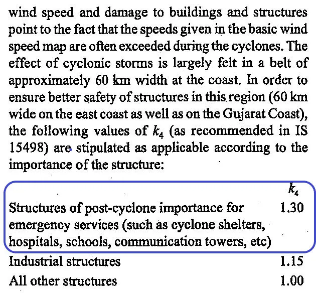
K4 - Importance Factor Refer IS 875 (Part 3) 2015 Clause 6.3.4 , As Our Structure is a Bridge Structure It Comes under category of Important Structure Therefore, we have to select 1.30 for K4
Design Wind Speed Vz = Vb x k1 x k2 x k3 x k4
Vz = 39 x 1.06 x 1.05 x 1.00 x 1.30
Vz = 56.4291 m/s
Wind Pressure Pz = 0.6 x Vz^2
Pz = 0.6 x 56.4291 x 56.4291
Pz = 1910 N/sqm
Pz = 1.910 kN/sqm
Procedure :
Modeling :
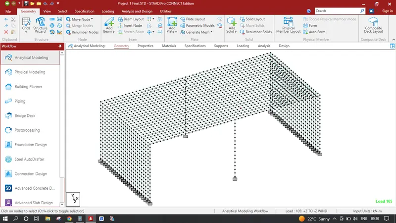
- 1. Open Staad Pro and Create a new Project and select Metric in Unit, this will allow us to model the structure in metres as shown in the given diagram and get results in Kn.
- 2. Input the origin node as 0,0,0 for and select the node and perform translational repeat number of steps 1 and distance is 8 Click Link Steps in Y direction, select all the beams and perform translational repeat number of steps 1 and distance is 12 in Z direction join top nodes with beam, select all the beams and perform translational repeat number of steps 2 and distance is 12 in X direction join top nodes with beams which creates our Piers and center and abutments at both ends.
- 3. Now we have to create a plate mesh which acts as a Abutment wall also it will be subjected to Earth Pressure Loading as well, select the origin node (0,0,0) press CTRL C+ CTRL V input 0.5 in Y and press ok again select both the nodes press CTRL C+ CTRL V input 0.5 in Z and press ok connect all the 4 nodes with plate select the plate and perform translational repeat number of steps 15 and distance is 0.5 in Y direction select all the plates again perform translational repeat number of steps 23 and distance is 0.5 in Z direction which creates our abutment wall at Abutment 1 Location, select all the plates and perform translational repeat number of steps 1 and distance is 24 in X direction which cretaes a plate mesh in Abutment 2 Location as well.
- 4. Create a Deck Slab Select the Top corner node (x-0, y-8, z-0) press CTRL C+ CTRL V input 0.5 in X and press ok, Select both the nodes press CTRL C+ CTRL V input 0.5 in Z and press ok. Create a Plate Inside these nodes select the plate and perform translational repeat number of steps 47 and distance is 0.5 in X direction, again select all the plates and perform translational repeat number of steps 23 and distance is 0.5 in Z direction which creates our Deck Slab.Which is Shown in the Image Below.
- 4. Now we have to Provide Supports in Pier and abutment wall bottom Select all the bottom Nodes Click on Specification in Upper Tab Create a Fixed Support and Assign the Bottom Nodes to Fixed end Support.
Assingning Specifications :
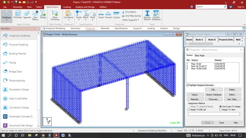
- 1. Click on Specification Tab click on Define click on Rectange Add a Pier Size of 1.0 x 1.0 m Click Add, Again Click on Define Click on Rectange Assign the Girders as 0.5 x 0.5 m. Again Click on Plate Thickness input 0.5m click add.
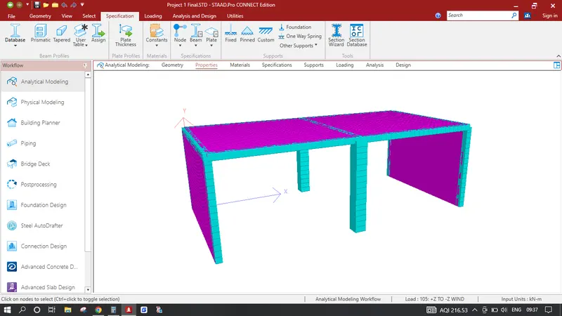
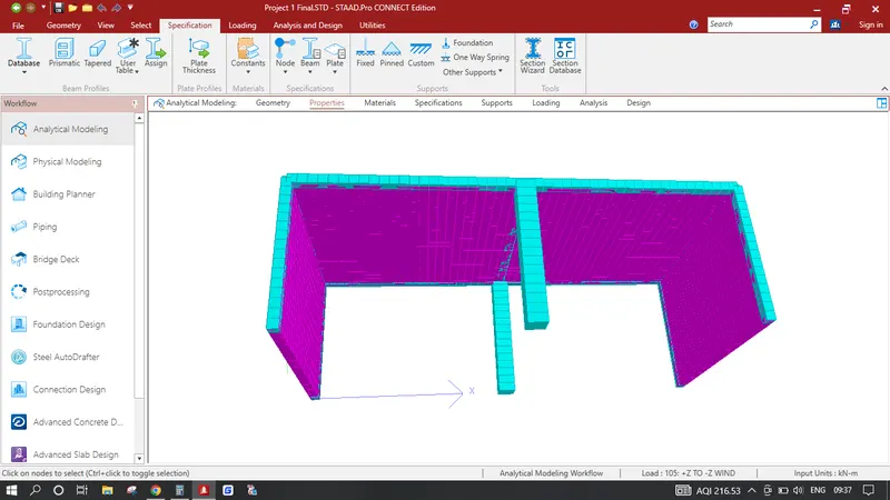
- 2. Select the Piers and Assign the Specification having 1.0 x 1.0 m Configuration, Similarly Select all the beams except the piers and Assign the Specification having 0.5 x 0.5 m Configuration, Similarly Select all the Plates and Assign the Specification having plate thickness 0.5m Configuration, After assigning all the properties the model should look like the image provided below.
Applying Loadings:
IRS Loading
- 1. Click on Loadings click on definitions again click on vehicle definition press add
- For Metro Vehicle Follow this input attached below
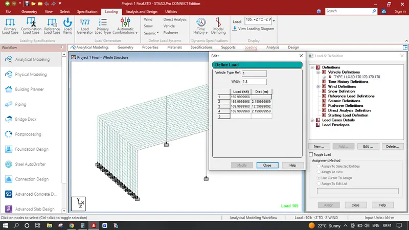
- 2. After adding definitions click on Load cases details and click add, click on load generation on left and in no. of loads to be generated enter 50 press add.
- 3. Under load cases details there is the 1-50 generated load file we have to assign the starting point for this load generation. select the file again click on add under initial point of load enter x-0, y-8, z- 3 and x increment will be 1. also add Z range as 12
- 4. Repeat the 2 & 3 points again this load generate file should have initial points x-0, y-0, z- 9 and x increment will be 1. also add Z range as 12
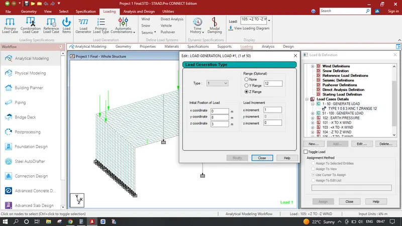
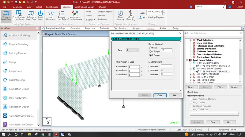
Earth Pressure Loading
- 1. Click on Loadings click on Load cases details Click add Under Primary Loads Write Earth Pressure click add
- 2. Click on Earth Pressure click add click on plate loads then hydrostatic loads click on select plates, select the abutment wall plates to the very left corner upto the height of 3m which is 6 plates towards Y direction, In W1 which is maximum load should be provided -54 Kn/m2 (Unit Weight of Soil 18 Kn/m2 and upto the height of 3m = 18 x 3 - 54), In W2 write 0, Interpolating along Y and Direction of Pressure is GX click add this creates different earth pressures of 54Kn/m2 to 0 interpolated along height of 3m.
- 3. As the loading applied in only one row of plates but we have to apply these loading into all the plates in abutment wall, first click on View in uppertab and click onto side view now click on first generated load and the by clicking it turns that plate into blue colour now select the plate in which shows the blue colour as you are in side view all the plates along that row is selected click on assign it to selected plates this will allow the model to apply the first load into all the plates in abutment wall of that row similarly select the second load and repeat the process repeat this process untill you reach the height of 3m By doing this it will allow the model to be subjected to earth Pressure in one side
- 4. Now we have to apply Backfill of height upto 5m loading but in reverse direction so that the loads created in point 3 will counteract, again click on Earth Pressure click add select the plate loads and select the Hydrostatic Loads click on select plates,select the plates in extreme left upto the height of 5m i.e. select 10 plates along Y Direction, In W1 which is maximum load should be provided -90 Kn/m2 (Unit Weight of Soil 18 Kn/m2 and upto the height of 5m = 18 x 5 - 90), In W2 write 0, Interpolating along Y and Direction of Pressure is GX click add this creates different earth pressures of 90Kn/m2 to interpolated along height of 5m.
- 5. As the loading applied in only one row of plates but we have to apply these loading into all the plates in abutment wall, first click on View in uppertab and click onto side view now click on first generated load and the by clicking it turns that plate into blue colour now select the plate in which shows the blue colour as you are in side view all the plates along that row is selected click on assign it to selected plates this will allow the model to apply the first load into all the plates in abutment wall of that row similarly select the second load and repeat the process repeat this process untill you reach the height of 5m By doing this it will allow the model to be subjected to earth Pressure in other side.
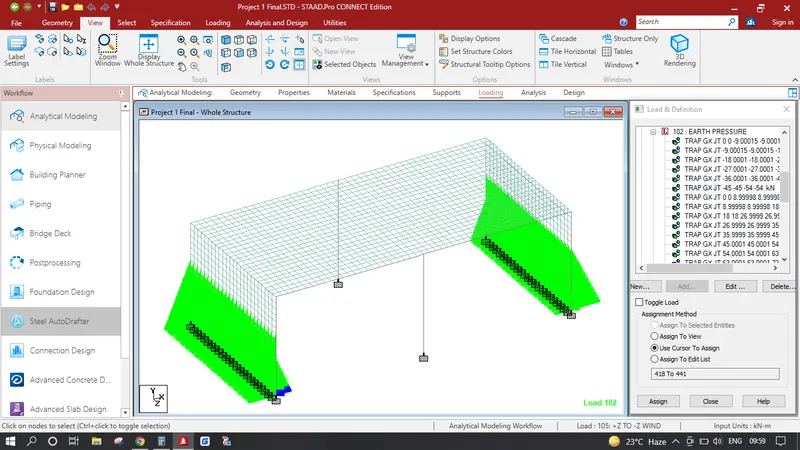
- This Process Completes the Earth Pressure loading in Abutment 1 Location Similarly Repeat the exact same process in Abutment 2 Loacation after the Loading has been applied it will look like the image provided below.
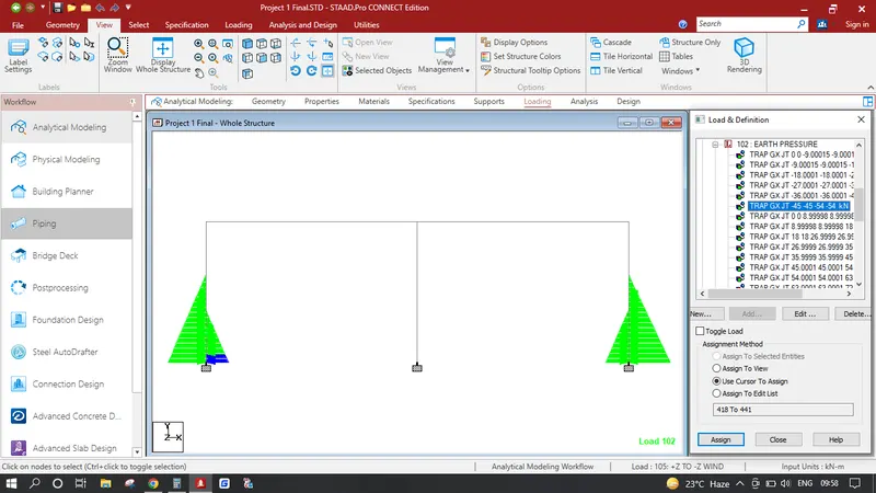
Wind Loading
- 1. Click on Loadings click on Definitions Click on Wind Definitions click add Wind 1 Click on Wind 1 Click add Input Value Given in Image
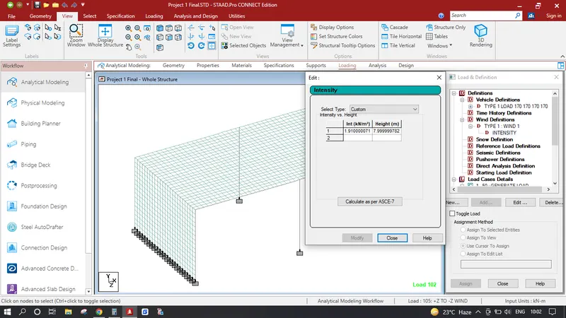
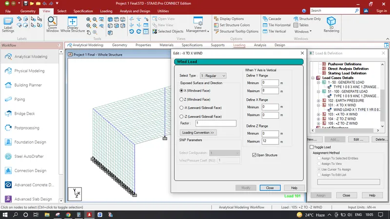
- 2. Click on Load Cases Details Click add Write Name -X TO +X Wind Load again Click on -X TO +X Wind Load click add and click on Wind Load and input values as provided
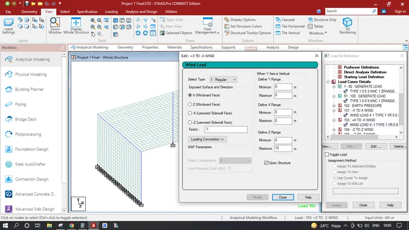
- 3. Click on Load Cases Details Click add Write Name +X TO -X Wind Load again Click on +X TO -X Wind Load click add and click on Wind Load and input values as provided
- 4. Click on Load Cases Details Click add Write Name -Z TO +Z Wind Load again Click on -Z TO +Z Wind Load click add and click on Wind Load and input values as provided
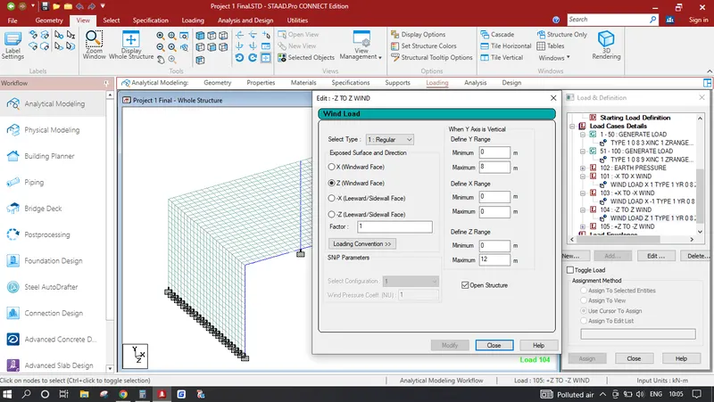
- 5. Click on Load Cases Details Click add Write Name +Z TO -Z Wind Load again Click on +Z TO -Z Wind Load click add and click on Wind Load and input values as provided
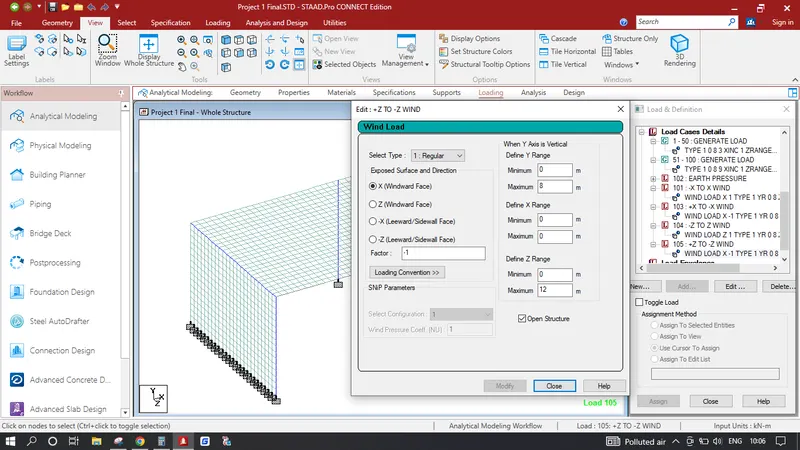
Seismic Loads :
- Click on Loadings click on Definitions again click on Seismic Definitions, under type select Indian IS 1893 2016 Part 1 after selecting click on Generate, select city as Ahmedabad, response reduction factor as 2.5 and Importance Factor Important Building it should be 1.5 click Generate
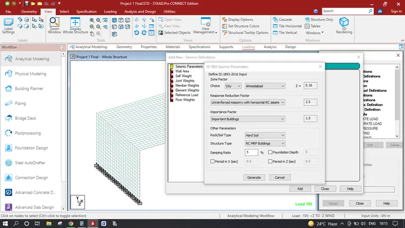
- Click on Load Cases Details add a Primary Load Case as Seismic Loads click add click on seismic loads direction X factor 1 click add which completes our Loading Applications in the model.
Analysis & Results :
- 1. Click on analysis and design run analysis, again go to post processing
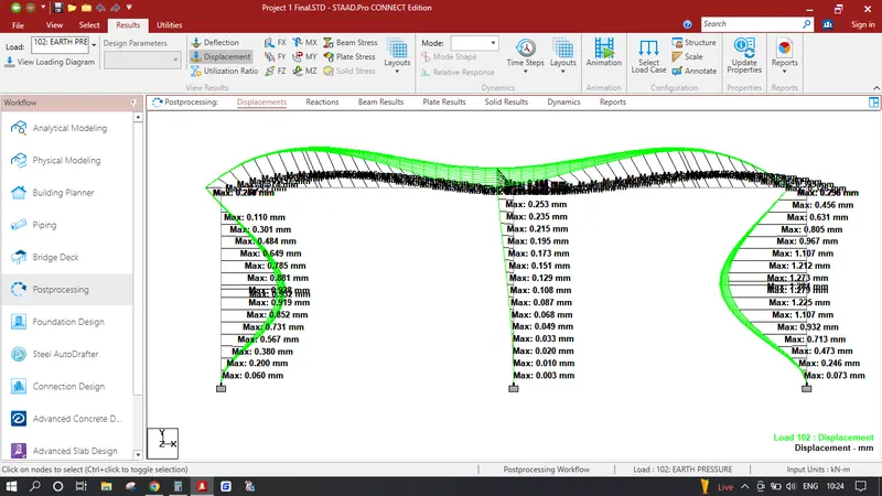
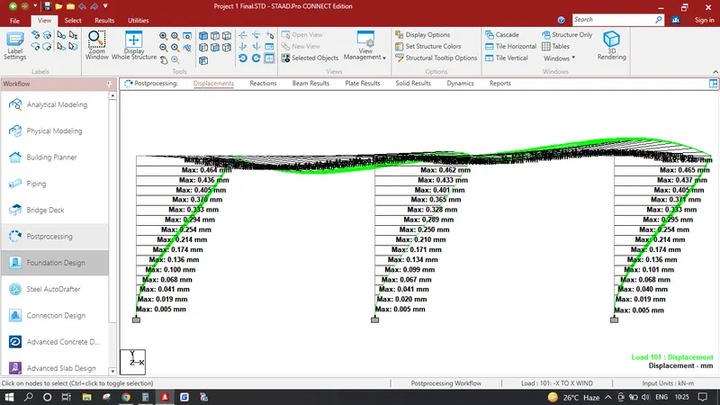
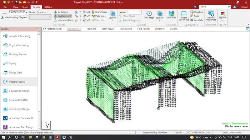
In Results Tab Displacement Pattern show in the image below
Displacement Pattern by Earth Pressure Loadings
Displacement Pattern By Wind Loads
Displacement Pattern By IRS Loading
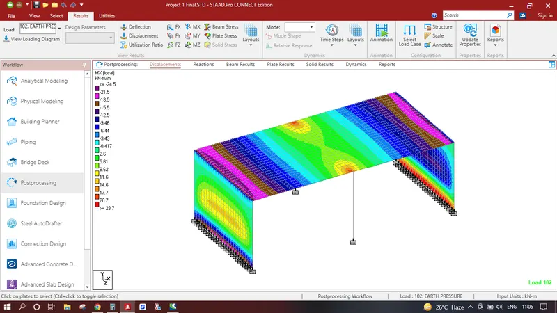
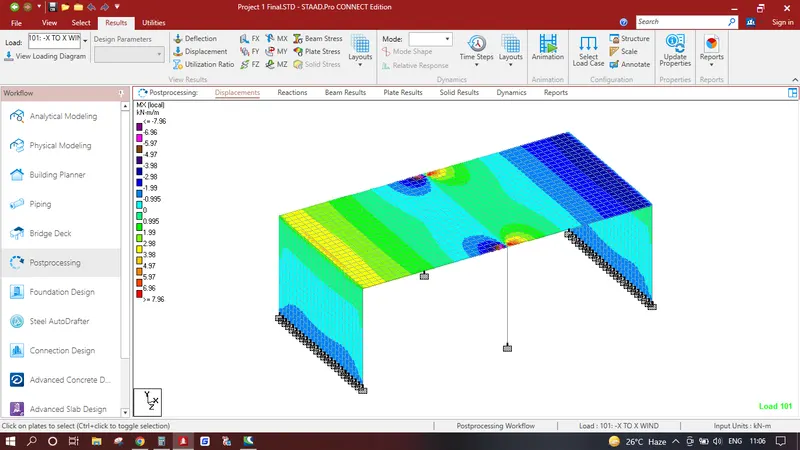
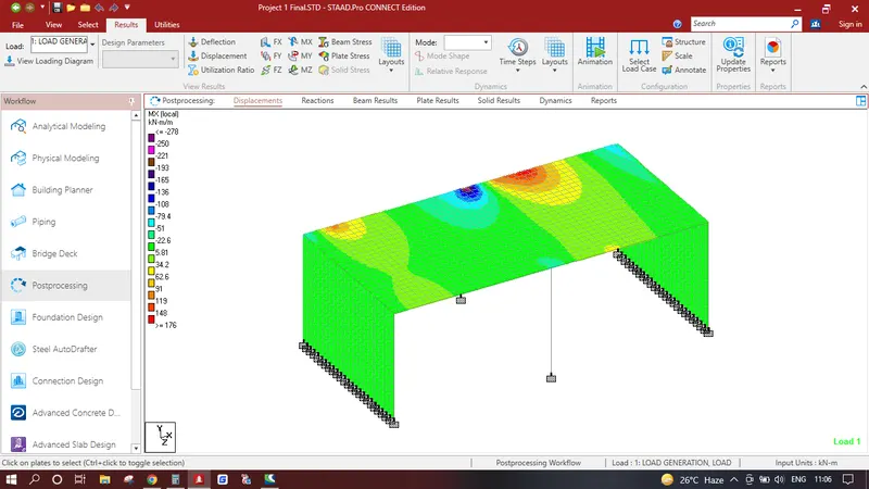
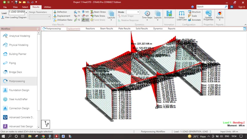
In Results Bending Moments shown in the image below
Bending Moments by Earth Pressure
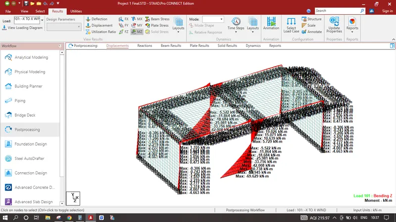
Bending Moments Wind Loads
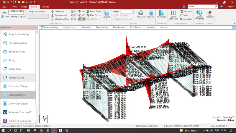
Bending Moments IRS Metro Vehicle Loading
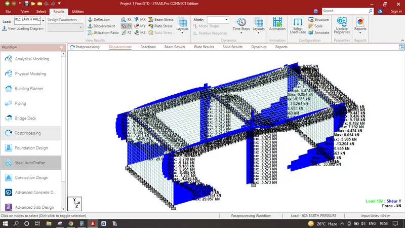
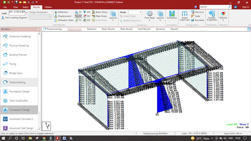
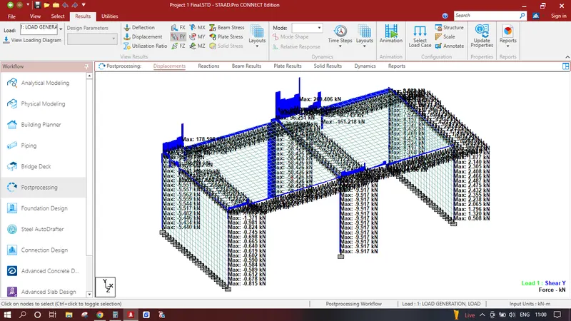
In Results Shear Stresses are shown in the image below
Shear Stress with Earth Pressure Loading
Shear Stress with Wind Load
Shear Stress with IRS Loading
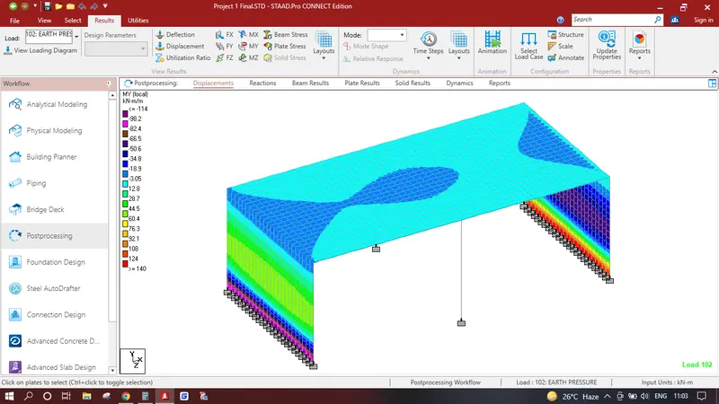
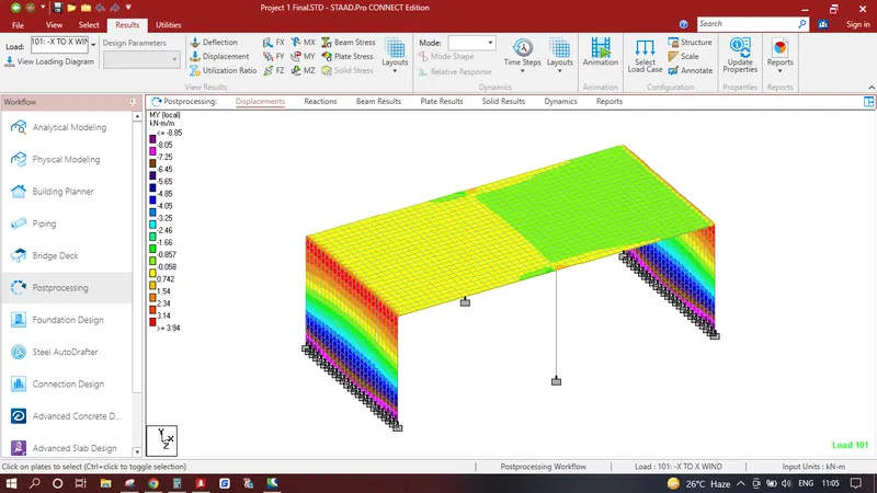
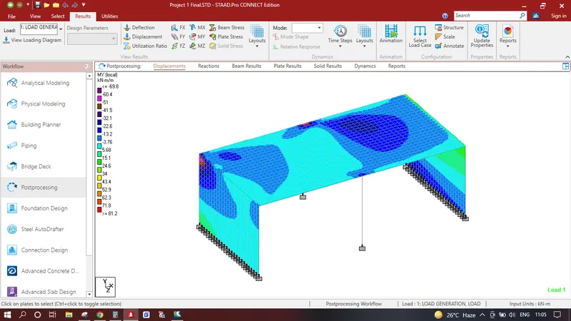
In Results Plate Stresses in MY Local are shown in the image below
In Results Plate Stresses in MX Local are shown in the image below