Project 1
Aim : To calculate the dead load, IRS live load, Earth pressure load, Wind load and seismic load for the bridge located in Ahmedabad metro rail project .
Given data :
Width of the bridge – 24 m
Span of the bridge is – 260 m
Unit weight of soil – 18 kn/m3
Load calculation :
- Dead load : By using the self weight the whole structure dead load will be assigned
- Live load : As per IRS the metro load can be defined.
|
KN |
Distance |
|
170 |
- |
|
170 |
2.2 |
|
170 |
12.4 |
|
170 |
2.2 |
- Earth Pressure :
K = k0 ɣ h
= 0.35 x 18 x 20
K = 105 KN/m2
- Wind load
Wind speed , Vz = Vb K1 K2 K3 K4
Basic wind speed, Vb = 39 m/s
K1 = 1.06 as per IS 875 part 3
K2 = 1.01 category 3
K3 = 1
K4 = 1.3
Vz = 39 x 1.06 x 1.01 x 1.3 = 54.27
Wind pressure, Pz = 0.6 x Vz2
Pz = 0.6 x 54.272 = 1.76 KN/m2
- Seismic load : This load can be directly defined in the Staad pro.
Aim : To define and assign the model in a STAAD Pro and perform the analysis and justify with the results.
 `
`
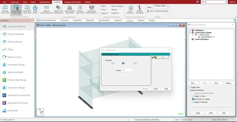
Defining the load cases .
Load case > add > click > selfweight > select > click assign to view > assign
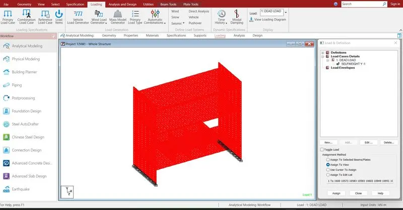
Dead load was assigned
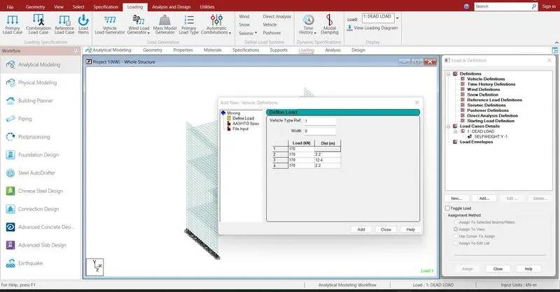
Loading > definition > vehicle definition > Add > define load
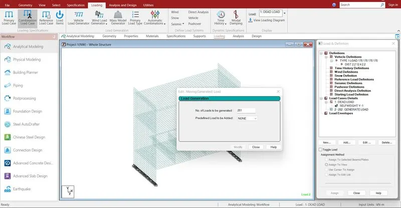
Load case > Add > load generation > add > give the range value to the exact loacation where the train will run.
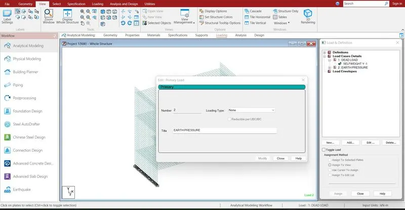
Load case > add Earth pressure > click > add plate load > hydrostatic > select plates > enter the calculated value > assign
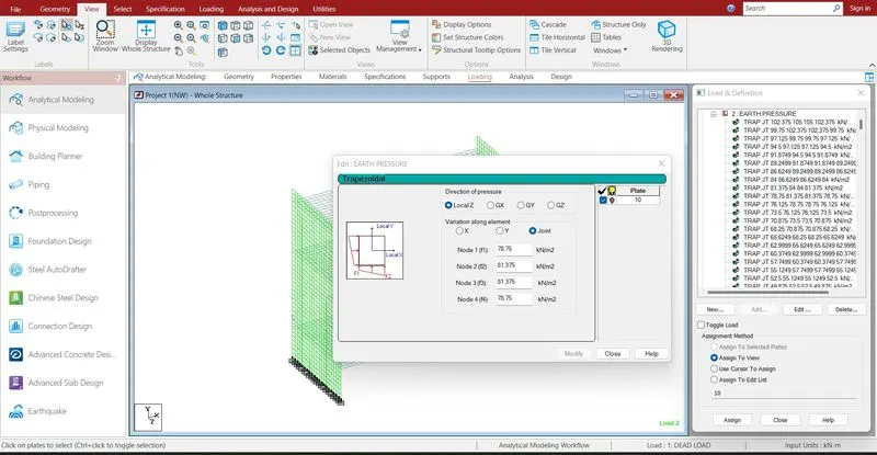
Earth pressure loads are assigned.
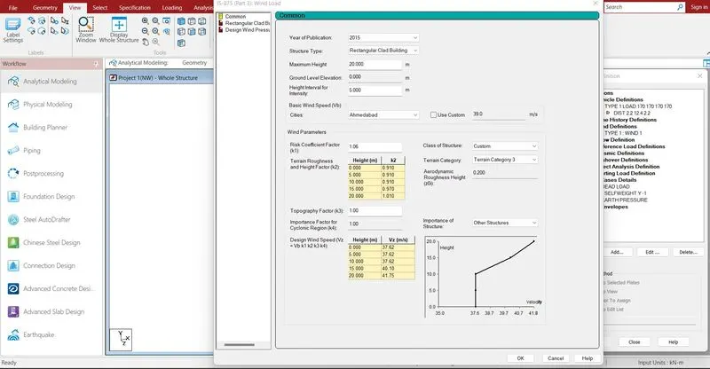
Loading > definition > wind load > select IS 875 part 3 > generate
load case detail > Add > wind load + X,- X, + Z, -Z direction
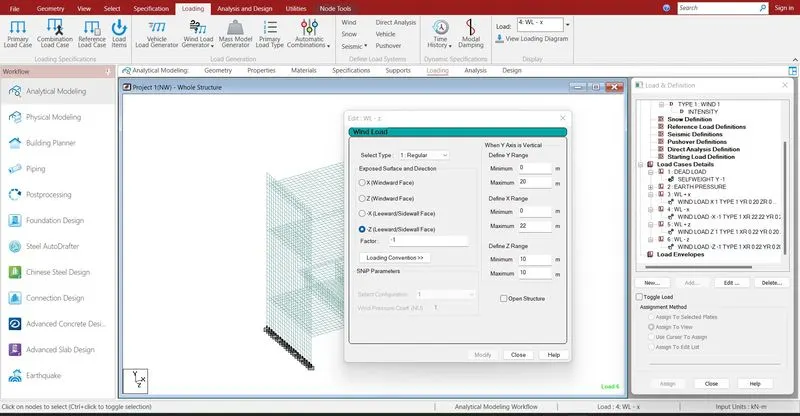
click each direction > give the ranges > assign
Wind loads are assigned
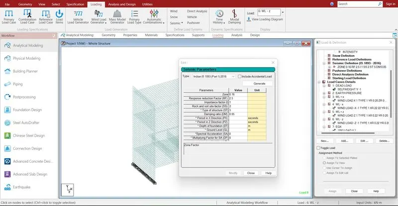
Loading > definition > seismic load > Add > select IS 1893 > generate > Add
Load > add > selfweight
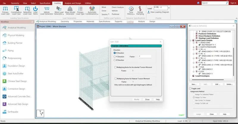
Load case > add EQX > seismic > X direction > add
Load case > add EQY > seismic > Y direction > add
Seismic loads are defined and assigned.
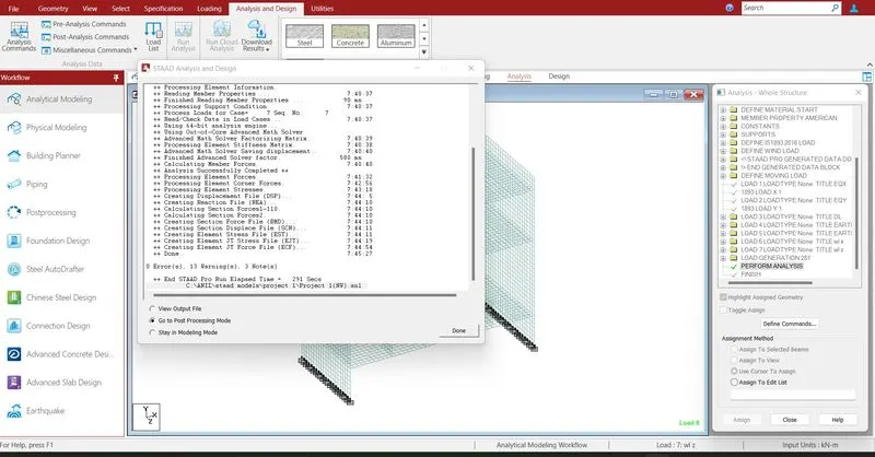
Run analysis > go to post processing mode > Results
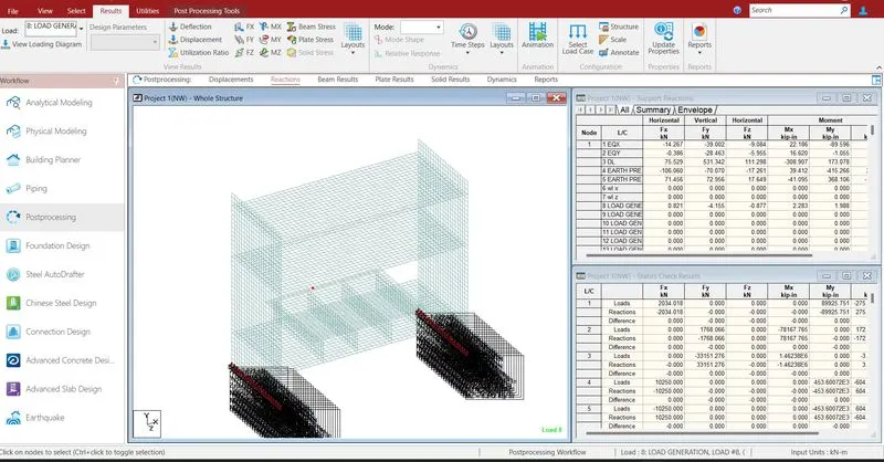
The reactions are generated at the end of the nodes .
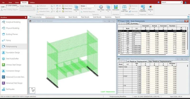
- The maximum displacement in X direction is 1.091 mm due to earth pressure
- The minimum displacement in X direction is -1.091 mm due to earth pressure
- The maximum displacement in Y direction is 0.1 mm due to seismic load in Y direction
- The minimum displacement in Y direction is -0.628 mm due to dead load
- The maximum displacement in Z direction is 0.002 mm due to dead load
- The minimum displacement in Z direction is -0.02 mm due to dead load
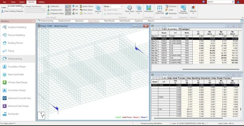
- The maximum shear force in X direction is 6.63 kn due to seismic load in X direction
- The minimum shear force in X direction is -90.411 kn dead load
- The maximum shear force in Y direction is 102.148 kn live load generation
- The minimum shear force in Y direction is -102.148 kn live load generation
- The maximum shear force in Z direction is 4.166 kn dead load
- The minimum shear force in Z direction is -4.356 kn due to dead load
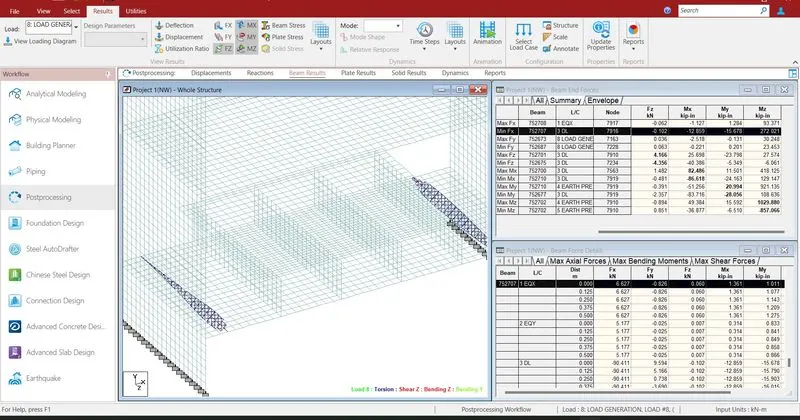
- The maximum bending moment in X direction is 82.486 knm due to dead load
- The minimum bending moment in X direction is -86.618 knm dead load
- The maximum bending moment in Y direction is 20.994 knm due to earth pressure
- The minimum bending moment in Y direction is -28.056 knm dead load
- The maximum bending moment in Z direction is 1029.880 knm due to earrth pressure
- The minimum bending moment in Z direction is -857.066 knm due to earth pressure
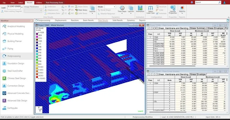
- The maximum shear stress at X direction is 112.879
- The minimum shear stress at X direction is -112.879
- The maximum shear stress at Y direction is 83.239
- The minimum shear stress at Y direction is 83.239
- Reports are taken printout which ever is necessary by using report option.
- In the report option we obtain the results of section forces, displacement, reactions, plate stresses.
- The exact report is to be taken further move to design process.