Project 1
PROJECT 1
Statement of assignment:
Route the Wiring harness on Given Engine and Prepare flatten view drawing in CATIA V5. Application of all Packaging rules, Industry best practices studied in this course shall be demonstrated in design. Apply Protection coverings as required.
Available connector 3D data can be used, or you can download the connectors from www.te.com
Prepare & Submit all necessary reports like clearance, Clipping/Clamping selection, Harness fixing requirements, Harness continuity, Assumptions if any along with CATIA 3D data.
Engine cad data to be downloaded from www.grabcad.com
DESIGN CRITERIA AND PACKAGING ASSUMPTIONS:
- Wiring harness routing shall provide ease in manufacturing, accessibility, easy removal, and easy maintenance of attached equipment and wiring harness.
- Routing through small structural holes and openings shall be avoided, minimize chaffing and handling of the wiring harness during installation.
- Avoid the harness routing and clipping in the Blind zone of the Operator during harness assembly or in service.
- Routing shall offer protection against possible damage through common misuses such as being handhold and temporary support for test equipment.
- Provide additional slack to the harness according to the surroundings and harness bending requirements. Ensure the routing meets the clearance requirements with different surrounding parts.
- Avoid routing over the bolts, near to the bolted joints. It may damage the harness or puncture the harness. Keep harness away from panel mounting screws.
- Avoid harness routing near sharp edges, if not possible provide protection to the harness. The maximum distance between two clips on a straight branch is 200mm.
- Provide Clips and clamps if the harness is going to bend at multiple locations. The use of too many sheet-metal brackets should be avoided.
- The branch length should be more than 50 mm.
- Min distance between clip and branching point to be 25 mm. Min distance between two branch breakouts should be 50 mm.
Steps For Route the Wiring harness on Given Engine-
Creating a Engine Harness Context Assembly-
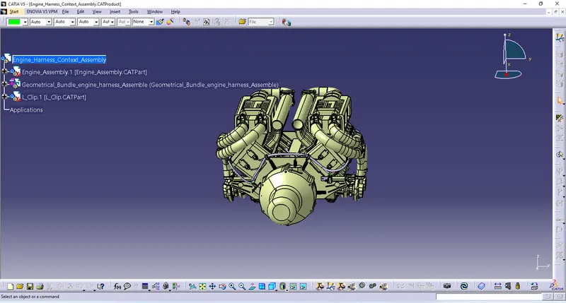
Add Engine Assembly Product file in Engine Harness Context Assembly
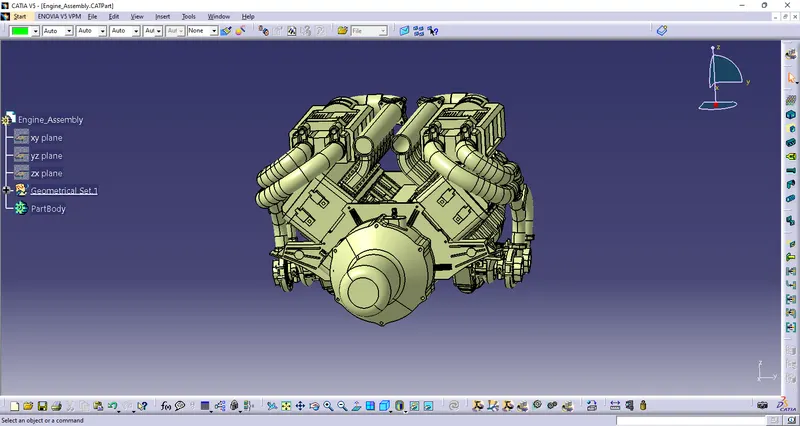
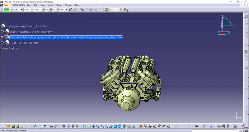
Creating a Geometrical Bundle Harness Assembly and add it in Engine Harness Context Assembly
Now we have to define the connectors as Electrical components.
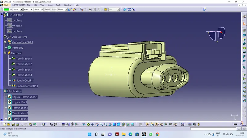
1) Connector(c-1563689-1-b-3d)_4_pole
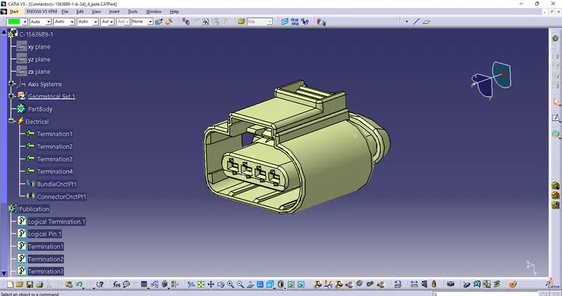
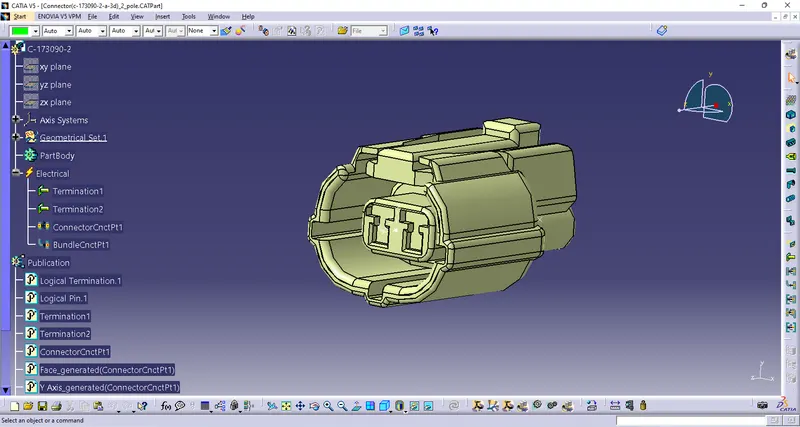
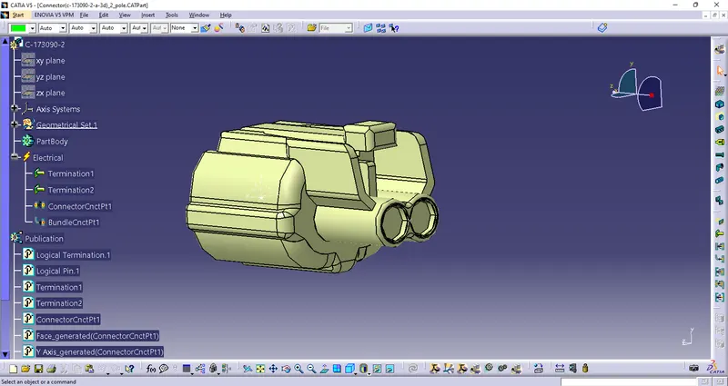
2) Connector(c-173090-2-a-3d)_2_pole
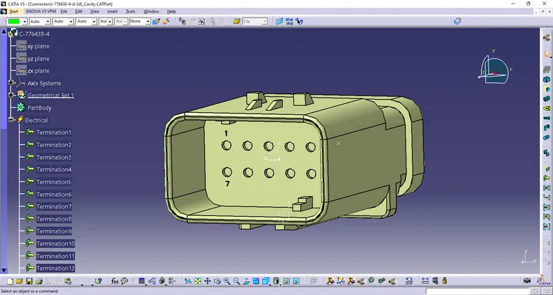
3) Connector(c-776438-4-d-3d)
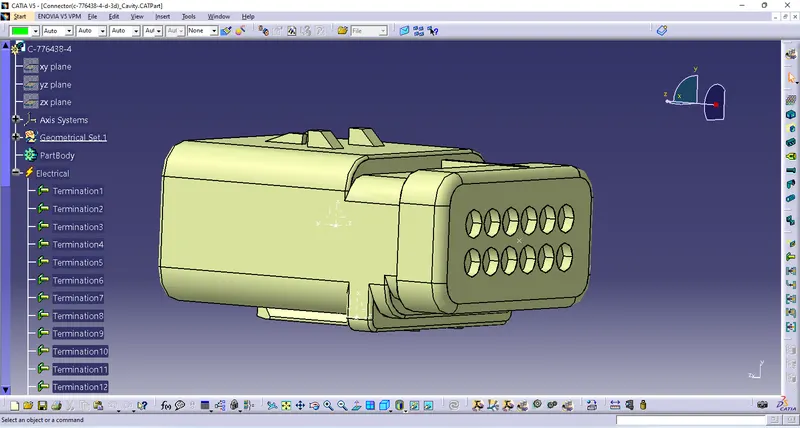
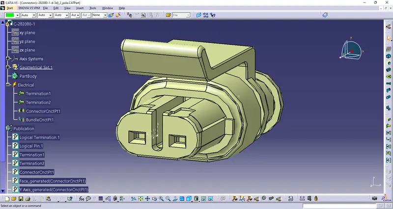
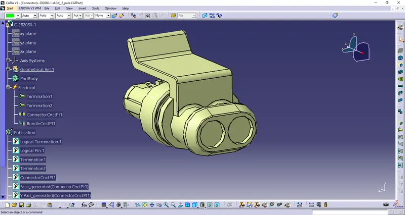
4) Connector(c-282080-1-d-3d)_2_pole
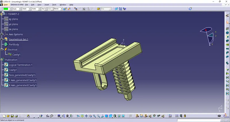
Defining mounting clip as Cavity
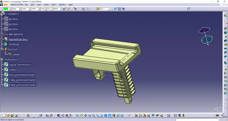
Now adding connectors to the all 16 fuel injector sensors and 4 cam-shaft sensors
In this step, we are placing connectors to fuel injector sensors and cam-shaft sensors. So we will require total 20 connectors which have to be added in the Engine Harness Geometrical Bundle Assembly. We have to use manipulation tools along with compass, snap and smart move features to locate all the 20 connectors at their desired locations.
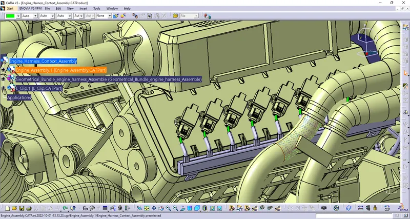
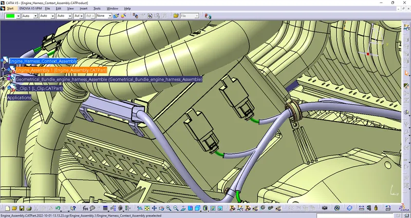
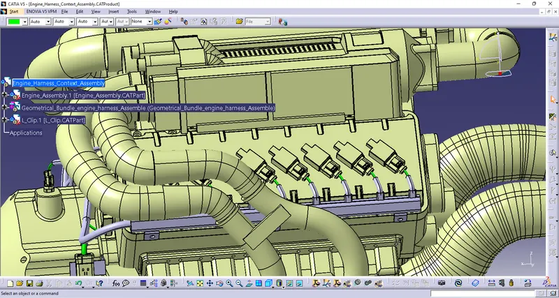
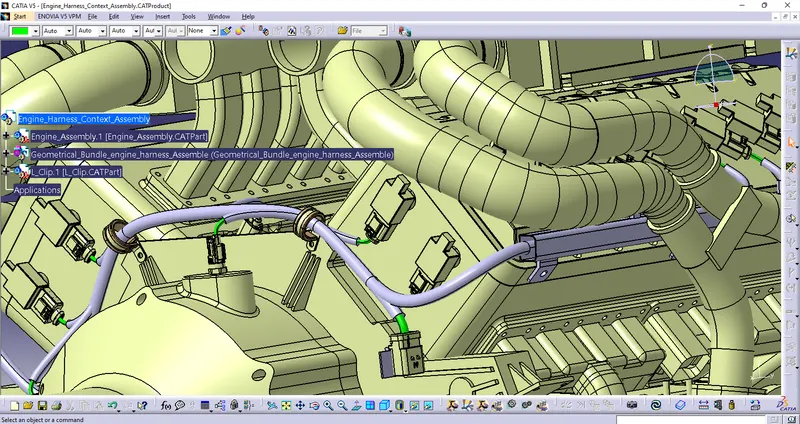
Inserting all remaining connectors into geometrical bundle and positioning them.
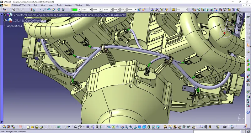
Adding sheet metal bracket for the interconnection connector
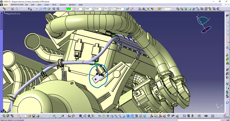
Mounting the interconnection connector and mounting clip on the sheetmetal bracket
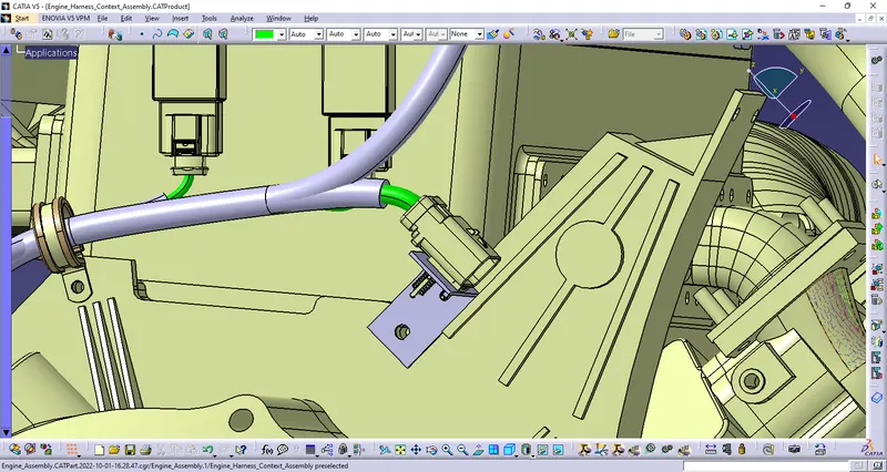
Adding P-clamps to provide positive clamping for the wiring harness
P-clamps should be defined with electrical properties before inserting into the geometrical bundle assembly
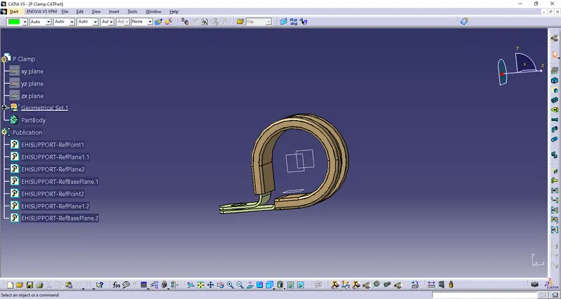
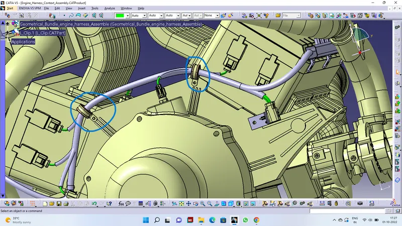
Now Adding plastic guiding channels
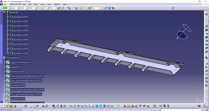
Routing the wiring harness to the connectors
Go to electrical harness assembly workbench and select geometrical bundle command and select the geometrical bundle in the model tree. Then select the multibranchable command to start the bundle routing and go to route definition.
1)The bundle routing starts from interconnection connector and then to the P-clamps and to the guiding channels.
2)Addding branching points wherever necessary using add branch point command as shown below.
3) Adding branches wherever necessary to connect the various connectors to the main branch as shown below using add branches command and routing definition into it.
4)To route the wiring harness through the guiding channels select external curve and click on the line in the guiding channel.
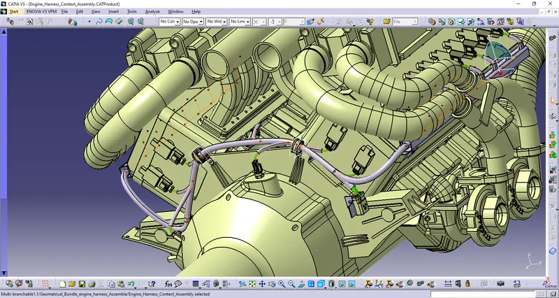
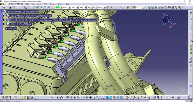
add protective cover on all routing branchess.
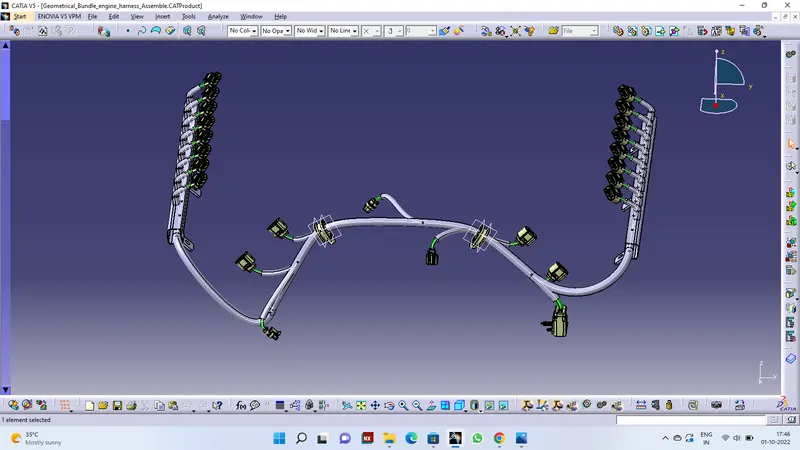
Thus the routing is completed as shown below.
We will check Bundle connectivity
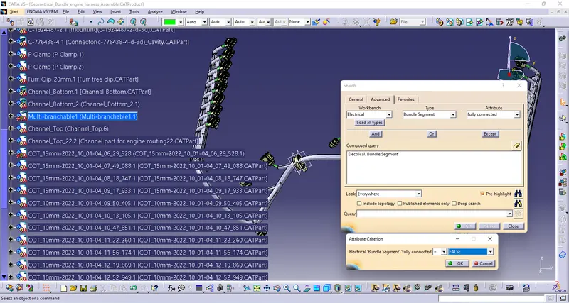
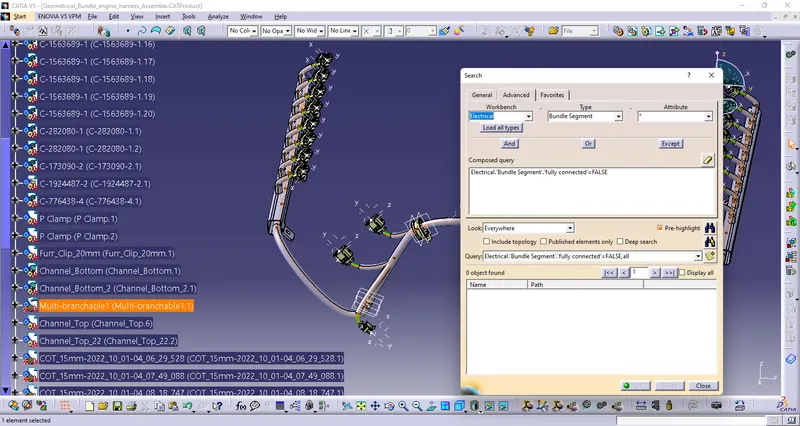
We will create a Product in Wire Harness Flatening and name it as Engine Harness Flatening Assembly
Define Parameters
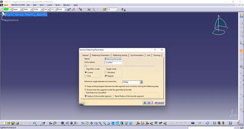
Extract Geometrical bubdle in Harness Flantning
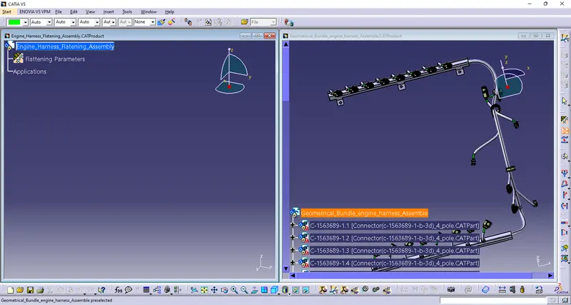
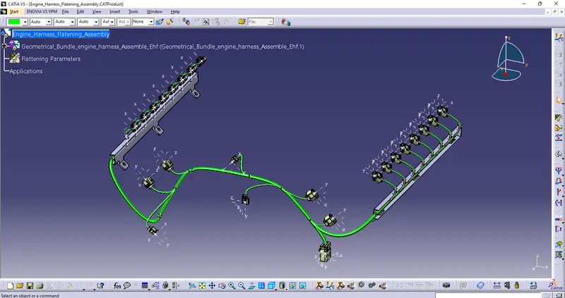
Use flatten command flatten harness budndle
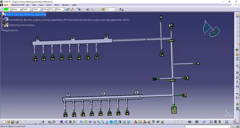
Create a drawing and use front view command to create a drawing of Harness_flatnening_Assembly
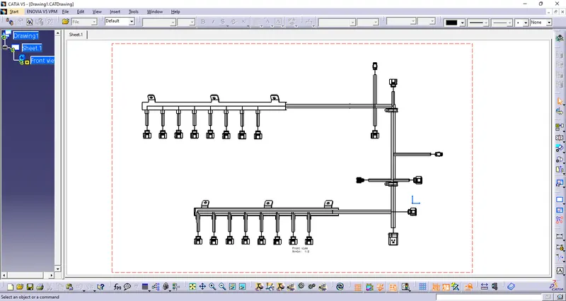
Conclusion: Thus the engine harness routing is completed and the flatten view drawing is created.