PREPROCESSING OF DASHBOARD SUB-PARTS USING ANSA v20.1.4
PREPROCESSING OF DASHBOARD SUB-PARTS USING ANSA v20.1.4
AIM :
To check for geometrical errors on the given CAD model of Dashboard Sub-Parts, extract the midsurface of the components and mesh with the given element Quality Criteria. Assign the appropriate thickness to the components.
FILE : DASHBOARD_IP
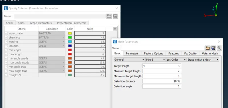
| Sl.No. | Quality Criteria | Value |
| 1 | Target/Average Length | 4 |
| 2 | Minimum Length | 2 |
| 3 | Maximum Length | 6 |
| 4 | Aspect | 3 |
| 5 | Warpage | 15 |
| 6 | Skewness | 45 |
| 7 | Jacobian | 0.7 |
| 8 | Minimum Quad Angle | 45 |
| 9 | Maximum Quad Angle | 135 |
| 10 | Minimum Tria Angle | 30 |
| 11 | Maximum Tria Angle | 120 |
| 12 | Tria Percentage | 15% |
PROCEDURE :
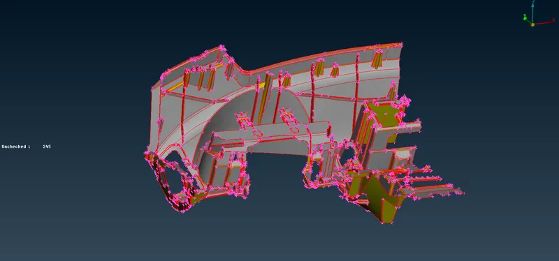
- The model of Dashboard CAD is opened in ANSA v20.1.4 using File>Open. The image below shows the model in the raw format as it was provided.
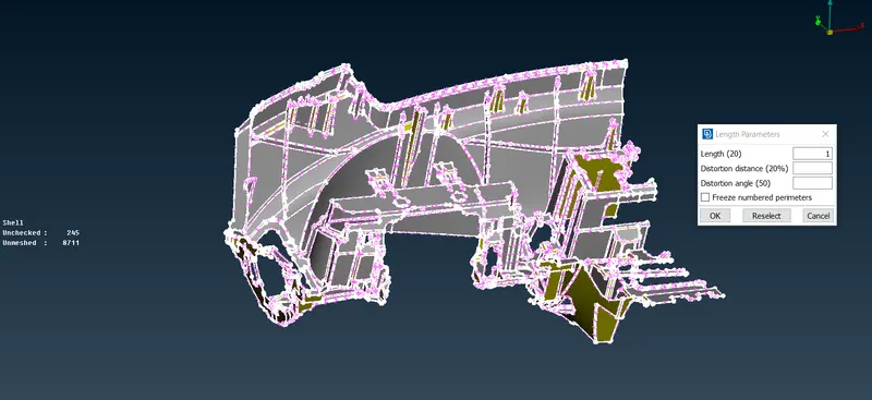
- The Length>Perimeter was set to 1mm to make the model for refined and complete topo was done to connect all the single cons to the adjacent sides. Then geometrical checkup was done.
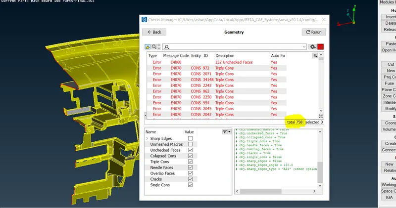
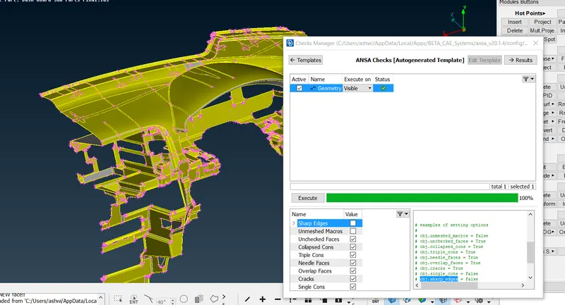
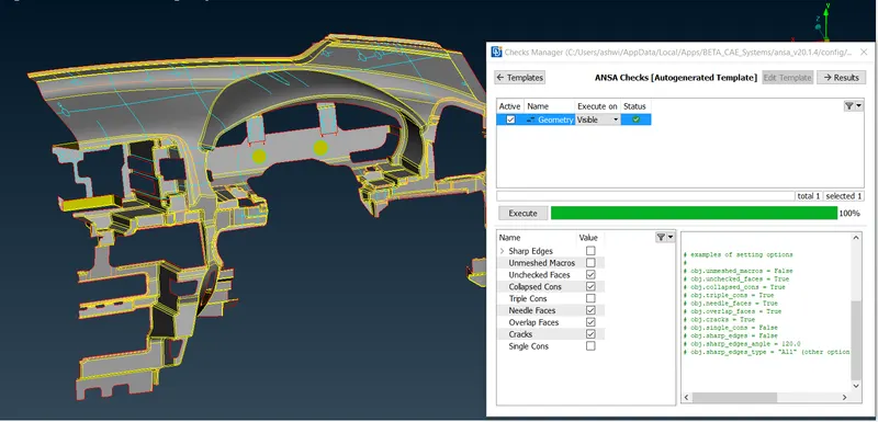
- All the geometrical errors where removed using the tools under Topo Module. Some errors were selected and the Autofix command was used to clear them. Most of the errors were cleared but there still some errors in the component which had to be cleared manually. After clearing all the errors the geometry check was executed.
- Measurements were taken at random edges to get an exact idea about the thickness of the components. This would be used while assigning the thickness to the model after mid-surfacing step.
- The midsurfacing was done manually using the offset option. While selecting the surfaces, the whole dashboard was selcted using the feature selection tab and an offsetof 0.3mm was applied on the surface.
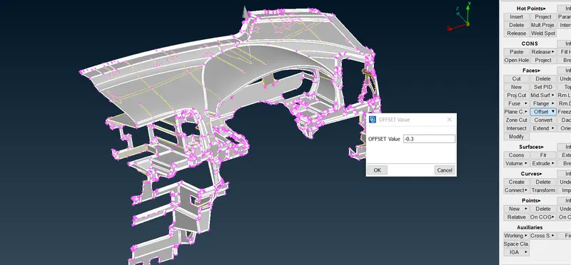
- After extracting the midsurface of the dashboard, the ribs and housing were mid-surfaced seperately since they where having different thickness.
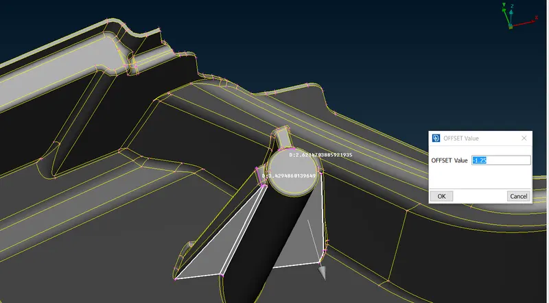
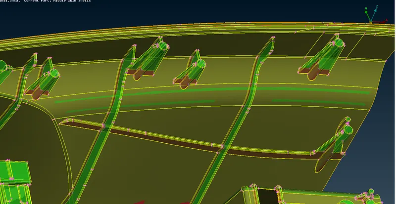
- All the seperate mis-surfaces are connected using extend and intersect depending on the scenario. In areas where the extend was not possible, new surfaces were created in order to join (new areas added to the component PID repectively).
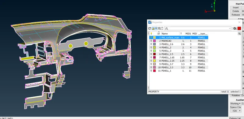
- Batch meshing was used to mesh the complete model. But before proceeding to that step, the geometry of the midsurface (uncheck singlecons and triple cons) was checked for any needle faces and cracks.
- Before the meshing step the quality criteria and meshing criteria were inserted.
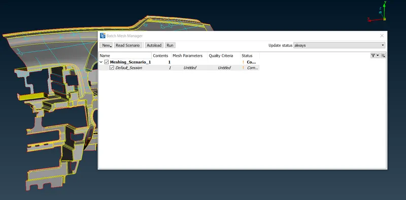
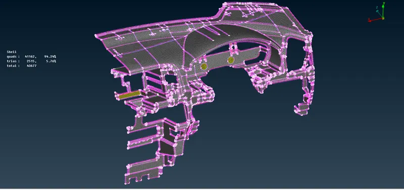
- Batch meshing scenario was used to mesh the complete the model. The model was divided into two parts before the meshing process. The main Dashboard as part1 and the ribs and housing as part2. The meshing scenario is done and all the off-elements where solved mained at error percentage less than 0.6%. And after meshing in order to see the thicnkess Draw shell as solid option was checked in the Quality Criteria tab.
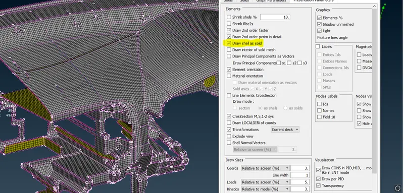
- Below is the fully meshed of Dashboard Sub-Parts.
LEARNING OUTCOME :
- Mid-surfacing components with varying thickness and connecting the mid-surfaced faces using extend and intersect tools .
- Batch meshing scenario with multiple parts.
- This project gave an insight into the actual Industrial Application of CAE used in automotive sector.