Project 1
Aim : Design and Develop a PWM controlled fan load with DC motor
Introduction :
- The primary emphasis of this work is to model a DC motor driven by an input signal that approximates a pulse-width modulated signal. These signals are fed to the motor using an H - Bridge circuit. Further, we focus on the implementation of speed control of a fan at the motor output. We assume that the change of operating speed of the fan is through stepwise modulation through a fan regulator
- The system using Pulse Width Modulation by establishing a connection between an H bridge circuit and a Dc motor. A fan type load equation has been used to analyze the output results instead of a physical model of a fan in Simulink. The speed of the fan is varied according to the input voltage using PWM technique.
- Pulse width modulation or PWM is a commonly used control technique that generates analog signals from digital devices such as microcontrollers.
H - Bridge :
The H-Bridge block represents an H-bridge motor driver. The block has the following two Simulation mode options: PWM — The H-Bridge block output is a controlled voltage that depends on the input signal at the PWM port.
DC Motor : Converts input electrical energy into mechanical motion
Pulse Width Modulation -
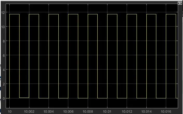
Pulse Width Modulation, or PWM, is a technique for getting analog results with digital means. Digital control creates a square wave, a signal switched between on and off. This on-off pattern can simulate voltages in between full-on and off by changing the portion of the time the signal spends on versus the time that the signal spends the duration of "on time" is called the pulse width. To get varying analog values, we change or modulate, that pulse width.
Load characteristics -
The torque speed curve of a load is a plot showing its torque requirement on the y-axis versus the speed on the x-axis. It’s the torque requirement of the load from zero speed to full speed. It is application/load specific and varies with different load types. Loads like centrifugal pumps and fans follow quadratic speed torque curve, where torque varies square times the speed. These are also called as constant torque loads or applications.
Simulink Model -
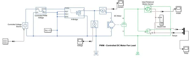
- This Shows the work for the design of the fan speed control system using Pulse Width Modulation by establishing a connection between an H bridge circuit and a Dc motor. A fan type load equation has been used to analyze the output results instead of a physical model of a fan in Simulink. The speed of the fan is varied according to the input voltage using PWM technique.
- By changing or modulating the timing of these pulses the speed of the motor can be controlled. A stepwise change in the speed variation is given and the full load speed is observed. In this model, all input ports of the H-Bridge block except the PWM port are connected to ground. As a result, the H-Bridge block behaves as follows:
- When the motor is on, the H-Bridge block connects the motor terminals to the power supply.
- When the motor is off, the H-Bridge block acts as a freewheeling diode to maintain the motor current.
Square Law as Fan Load -
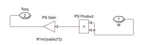
Model Explanation:
- Torque exerted by fan represented by TL
- Load torque i.e. TL proportional to square of speed i.e. wm^2
- TL = C . wm^2
- By varying the electrical parameter of motor i.e. voltage and current we are controlling load torque or load speed.
- For fan load we don’t have any block to represent a fan so we are representing by a subsystem to the left side there is w and it is multiplying by product block then it is become w^2
- Then gain block is used that is the constant of proportionality 8.8e-8 Unit of this gain block is N*m/(rad^2/s)^2 Output of this subsystem is fed to the Aerodynamic block. Actual name of this block is Ideal torque source block. This ideal torque source block is going to apply torque on the shaft of DC motor.
The Controlled PWM Voltage block represents a pulse-width modulated (PWM) voltage source. You can model electrical or physical signal input ports by setting the Modeling option parameter to either:
- Electrical input ports— The block calculates the duty cycle based on the reference voltage across its ref+ and ref- This option is the default.
- PS input— Specify the duty cycle value directly by using an input physical signal port.
- The H-Bridge block represents an H-bridge motor driver. The block has the following two Simulation mode options-
PWM — The H-Bridge block output is a controlled voltage that depends on the input signal at the PWM port. If the input signal has a value greater than the Enable threshold voltage parameter value, the H-Bridge block output is on and has a value equal to the value of the Output voltage amplitude parameter. If it has a value less than the Enable threshold voltage parameter value, the block maintains the load circuit using one of the following three Freewheeling mode options.
H-bridge used to change the direction of motor. Basically, it is used to turn the motor is in clockwise direction or anti-clockwise direction.
we can use a H-Bridge motor driver for the DC motor which helps in reversing the polarity of the motor to run it in the reverse direction. So whenever the brakes are applied the command is given to the H-bridge and it reverses the polarity of the motor thereby making it works as the generator and the energy produced is given to the batteries.
Result :
The plot of Fan load torque, H-Bridge output voltage and current output is as follow -
Fan load torque - 914 Nm
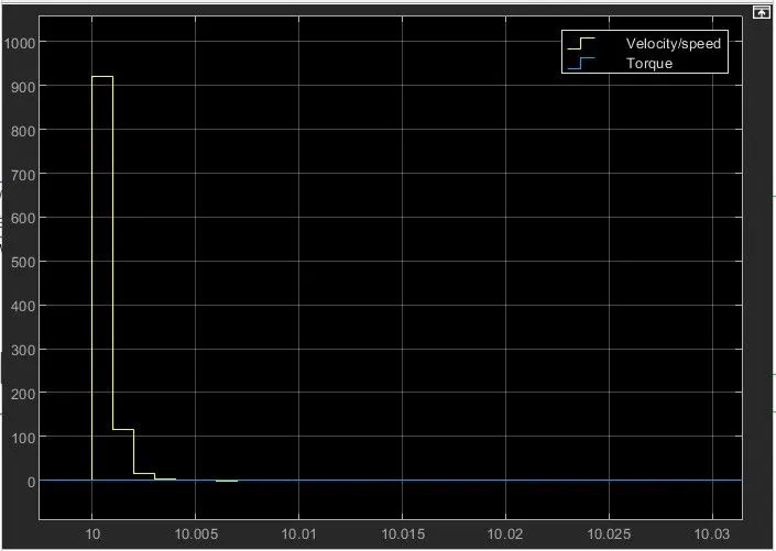
H-Bridge output current - 3 Amp
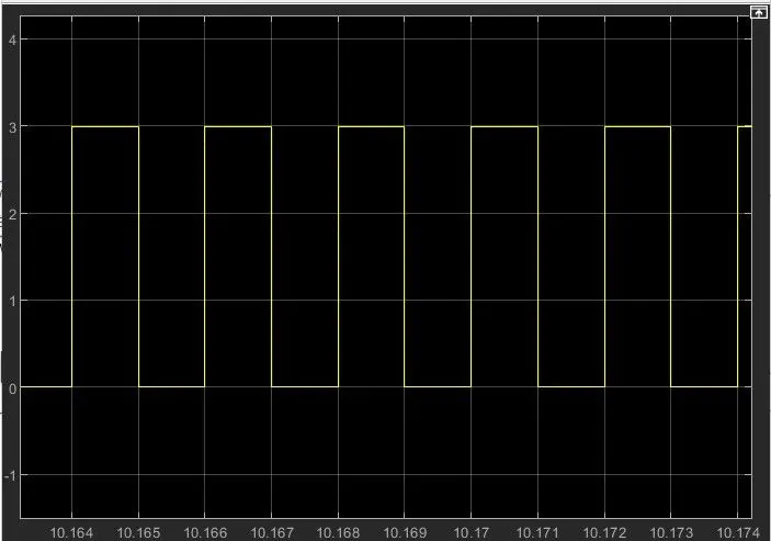
H-Bridge output Voltage - 11.7 Volt