Week - 4
Q.1 Implement control logic of ‘ Washing Machine’ using stateflow as per given sequence.
If the power supply is available, the system gets activated
If the water supply is not available ,stop the process and indicate through LED
Soaking time should be 200s , followed by washing time of 100s
Then rinsing happens for next 20s & dryer runs for 50s
After all the process have completed turn on the finished LED
Answer :
Basic info about washing machine -
Washing machine works on the principle of centrifugation. Centrifugation is a separation process that use the action of centrifugal force to promote accelerated settling of particles in a solid liquid mixture.
Washing machine complete the its whole process in following 4 stages:
- Soaking – Soak function is used to dip cloths in detergent to remove dirt from clothes
- Washing – washing is done with water and detergent
- Rinsing – The dirty , soapy water is drained , then the washing machine is refilled and clothes are rewashed in clean water.
- Dry run – used highest spin cycle suitable for clothes load and air dry clothes
Stateflow – Matlab stateflow is a graphical representation of FINITE STATE MACHINE.
State machine is an event driven system, the system response to an event by making a transition fron one state to another and this transitions are occurred if the condition defining change is true
As per the condition sequence given in the question I design a control logic for washing machine.
Blocks used to implement stateflow –
- Chart – stateflow chart block used to implement the different states for the control logic of washing machine
- Constant block – used to provide input values of power supply and water supply
- Display blocks – to observed running operations as value 1 and 0
- Lamp – lamp block is used to indicate running condition or operations
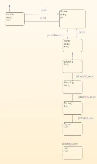
We use 8 state blocks in chart to represent
power supply (S),
incoming power (p),
water supply(X),
soaking(A),
washing(W),
rinsing(R),
dryrun(D) and end state(E) as shown below :
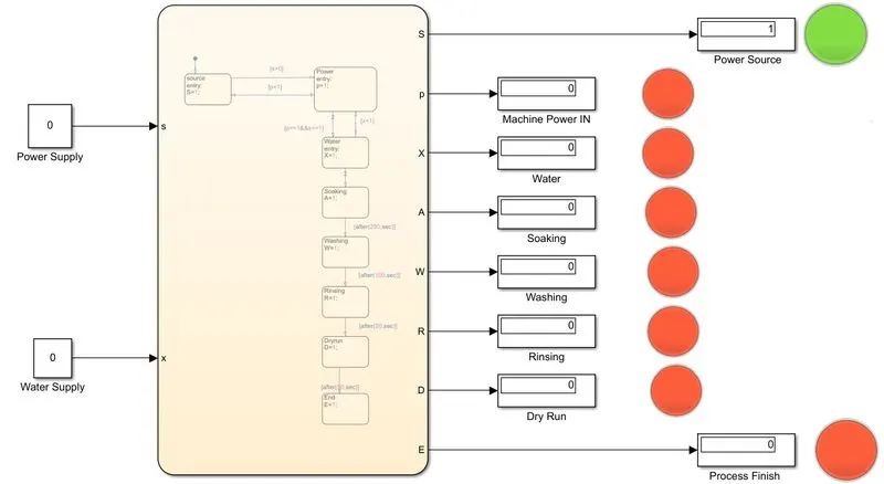
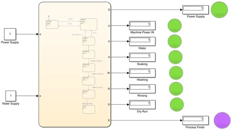
If constant blocks value is 1 , means power supply and water supply is present as we can observe on the display and indicated by lamp with green colour and if constant block value is 0 , then power and water supply is absent and system is off this condition is indicated by lamp with red colour.
When power supply is available but water supply is absent whole system is off.power source lamp indicates green light because it is connected to the system but Machine Power IN lamp is RED because main supply is not present to ON the machine As given below :
When power and water supply both are present that is 1 then, soaking state is activated and deactivate or off after 200 sec as per the condition we apply there. There after washing state is active and off after 100 sec.
Then Rinsing process runs if (R = 1) for 20 sec after that dry run is starts then after 50 sec process end when E=1 and indicated by lamp with purple colour as shown below :
Q.2 make a simulink chart for the ‘”Gear Shift’’ logic as per below conditions :
Speed Range (Kmph) Gear
0 to 15 1
16 to 25 2
26 to 40 3
41 to 60 4
Above 61 5
Give speed input while simulation is running & display the gear number.
Answer :
Blocks used :
- Constant block – used as START/STOP button for car mechanism
- Lamp block – lamp is used to indicate the car is ON or OFF
- Slider Gain block – used as a accelerator to vary the speed
- Chart - used to implement contro logic for gear shifting of car
- Display block – used to observe gear position
When value ‘1’ is given to the constant block that is represent Engine is on and indiated by lamp with green light and if engine off lamp indicate with red light.
when engine is ON we adjust the speed input with accelerator and as per the condotions given in question we assign states in chart.
The states of chart are given below :
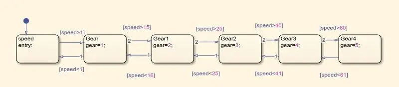
if engine is ON and speed input is at 13 kmph then display represent gear number 1.
As we can observe below :
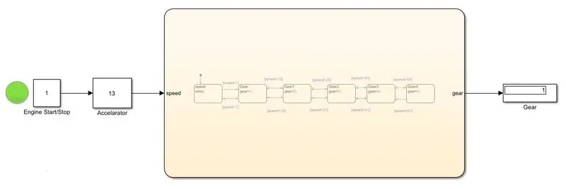
if speed is more than 15 Kmph then display represent gear number 2.
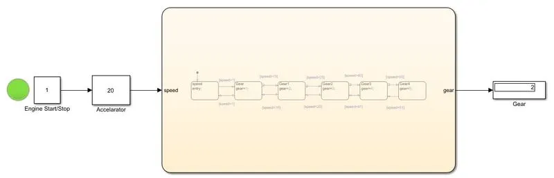
Result :
1) We successfully implement the control logic for washing machine using stateflow and achieved the condition sequence.
When power supply is available system is ON otherwise system is OFF and display shows value ‘0’ and lamp indicate RED light.
When water supply is absent process stop lamp or LED indicate RED light , if water is filled / available process starts and lamp glow with green light.
Soaking process done within 200 sec followed by washing time 100 sec and Rinsing is done for next 20 sec then dryer runs for 50 sec.
2) Run the simulation for given speed range and observe the gear number on display as speed is between 0 – 15 Gear is 1 , if greater than 15 Gear number 2 .
If speed 16 – 25 Gear 2, and for greater than 25 Gear number 3.
If speed 26 – 40 Gear 3 and for greater than 40 Gear number 4
If speed 41 – 60 Gear 4 and for more that 60 Gear number 5.