Performing Mesh on a Car Dashboard
AIM:
The main objective of the project is the given sheet metal component Dashboard assembly has to be meshing for structural analysis using the ANSA (Automatic Net generation of Structural Analysis) software for solving the issues and improves the quality of the component to make the product safe. In this project, we applied some quality criteria like Average, minimum length, maximum length, warpage, and many more.
GIVEN DATA :
As per Industry standards,
|
S.No |
Quality Criteria |
Value |
|
01 |
Target/Average length |
4 |
|
02 |
Minimum length |
2 |
|
03 |
Maximum length |
6 |
|
04 |
Warpage |
15 |
|
05 |
Aspect ratio |
3 |
|
06 |
Skewness |
45 |
|
07 |
Jacobian |
0.7 |
|
08 |
Minimum quad angle |
45 |
|
09 |
Maximum quad angle |
135 |
|
10 |
Minimum tria angle |
30 |
|
11 |
Maximum tria angle |
120 |
|
12 |
Tria percentage |
15 |
FORMULAE:
Here we using very simple formulas during applying the quality criteria and it’s already programmed in the ANSA software. The formulae are,
- Aspect ratio, max
- Warping angle, max & more.
DASHBOARD:
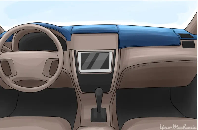
A dashboard is a control panel usually located directly ahead of a vehicle's driver, displaying instrumentation and controls for the vehicle's operation. It is also called Dash, Instrument panel(IP), and Fascia. It indicates about speed, fuel, control steering wheel, air conditioning and now modern days it also indicates about oil pressure, weather, lights and in dashboard LED screen are given where we see the operation of parking and front camera, music system, and GPS control system are also attached. So we can see the whole working and movement of the vehicle and it's part to control them.
PROCEDURE:
- Open the latest version of ANSA software in your system.
- Import the given sheet metal cad geometry file (.step) in the ANSA, it will automatically change their file extension into ANSA readable file(.ansa).
- Identify the topo errors present in cad geometry, by the way, check > geometry present in the top.
- The topological errors are notified as a single con, triple cons, cracks, overlapping faces, and many more.
- Understand the reason for the error and perform the actions to resolve it.
- Material identities(MID) and part identities(PID) should be set before doing the meshing operations.
- Extract the middle surface of the geometry, they are several ways to achieve it like manual mid-surfacing(faces>offset) and automated one(faces>mid. surface).
- Change the module (topo – mesh) and perform the 2D mesh with your favorite mesh operations like free mesh, best mesh, spot mesh, etc.,
- Check the mesh quality with the given quality criteria and resolve if any error occurs.
Importing :
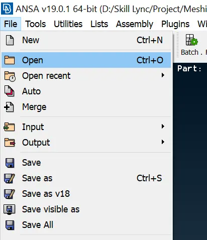
Open the latest version of ANSA on your Pc/Laptop. Import the cad geometry files through file > open or Ctrl + O.
CONS:
There are three types of cons,
- Single con - Red in colour, single free edge con.
- Double con - Yellow in colour, Shared by two neighbouring connected faces.
- Triple con - Blue in colour, Shared by three or more connected faces.
TOPO:
Topology is the process, which makes the topological connection to the faces automatically by selecting the feature.
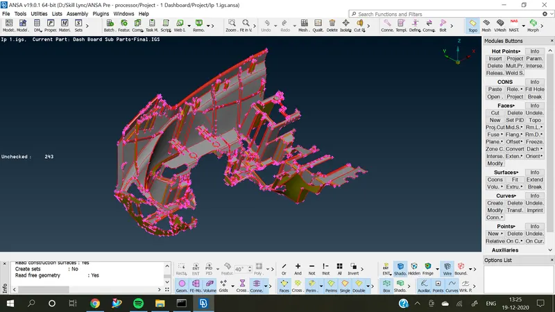
Here, the above image has been taken the applying the Topo to the feature.
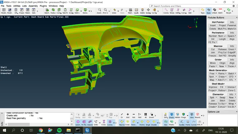
After performing topo, the cons are connected to each other.
Geometry check :
Topological errors have to be checked for the given Instrumental panel through the following steps – Tools > checks > geometry
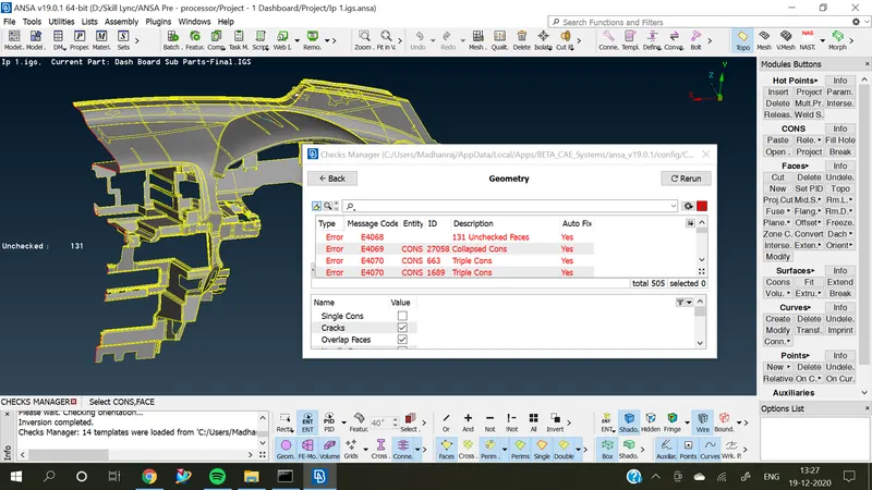
After checks the geometry, If there is an error is present then the check bar will show the error with its type, message code, entity, ID and reason like cracks, triple cons, collapsed cons, needle face etc., and also its shown if the error has been by auto fix itself that’s a great advantage for us.
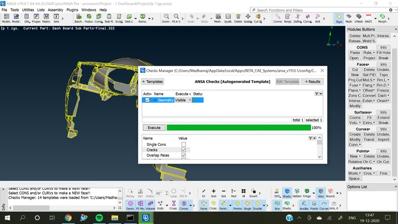
If the error has been able to clear with the use of auto fix then,
We have to done with ~ ctrl+A to select the whole errors then right-click the mouse and fix it. After the problem has been resolved then the check manager will be shown the execution is 100% like below.,
Mid - Surface :
Mid – Surface extraction is the method to simplify the meshing operation. If we didn’t use the mid surface then the simple geometry of meshing process can take very long time to achieve the proper result.
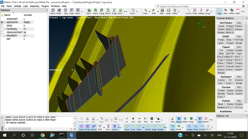
NOTE:- Please untick the option[Delete Original Faces]
Mid-surface extraction is creating a shell in the middle of the outer and inner surface of a solid model or geometry. It converts the solid geometry into a thin shell, which reduces the time taken for meshing by reducing the areas to mesh.
Dach:
Dach is the process of dividing the faces by the areas like a fillet. [Face > Dach > Divide face]. In this project, most of the fillet region are fails for Quality. so we can simplify Dach the particular area and resolve the issues.
Set PID & MID
Assign PID for every single region, so we can identify the part very quickly and view their property as a separate menu bar. To assign property,Face modules > Set PID > faces/shells. Complete all the single region as a single part.
Setting PID (property ID) and MID (material ID), which is the most important thing that we don’t forget to perform ~ Topo > Module buttons > Faces > Set PIDFirst, we select the surface and property bar will open like this
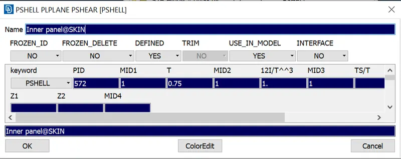
We can develop the mid surface every part and assign the property ID to all. Double click the property of the part.’ T’ which indicated the values of the thickness and ‘MID’ which indicates the material ID(shift +?) to get the material details to be sure er need to get the tick in the box.
By using the measurement, we can separate the properties for the areas.
Quality criteria:
These Quality criteria will make us understand how much the elements deviate from the ideal element. Since they represent the geometry during the simulation, poor elements will misrespect the geometry and the lead to inappropriate results.
Meshing :
After transforming the solid part into the shell to be created, assign the target element length as 4 mm and the type is a mixed element
Assign the Meshing quality criteria(f11) that were given in the Project.
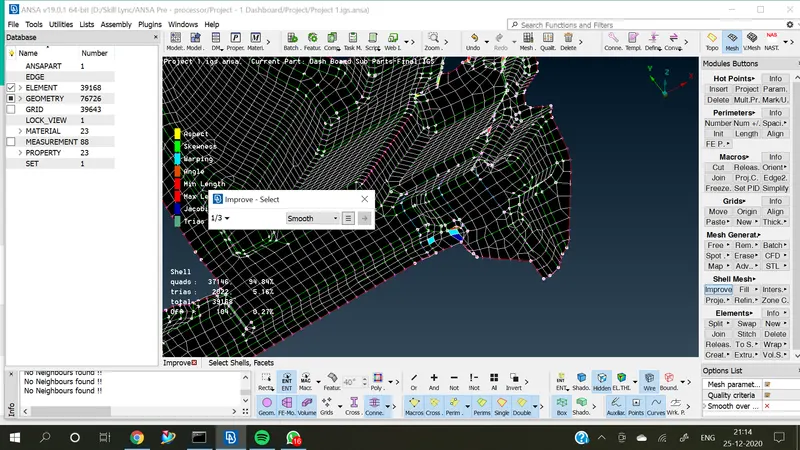
In this project, I use both Batch mesh and Manual mesh. For some plain areas, we use Batch mesh and we have to rework as much as possible to resolve the errors.
Types of mesh
Here some of the mesh types, I used to simplify the elements are
- Spot Mesh
- Batch Mesh
Spot Mesh method👇:
To use Spot mesh - [ Mesh module > Mesh Generation > Spot ]
Spot mesh is a manual mesh method that takes more hours but it's a very safe method because while doing with batch mesh we are unable to check every single area while the mesh is good or not.
Batch Mesh method👇:
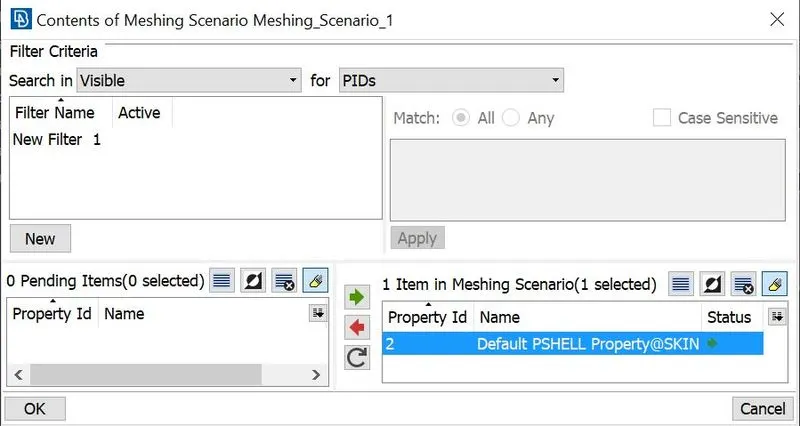
The batch mesh is a very usual method, which helps to finish the whole meshing in a very quick time. we just give some input to the meshing scenario, the whole mesh was automatically performed by the ANSA.
Create a new meshing scenario, Add content to the scenario and apply the Quality criteria and the mesh parameter as per the above figures.
After giving all the input, which will take minutes to perform, it varies as per the CAD file.
Once it's complete, Clear all the errors and check whether every area has performed well and there are no deviations.
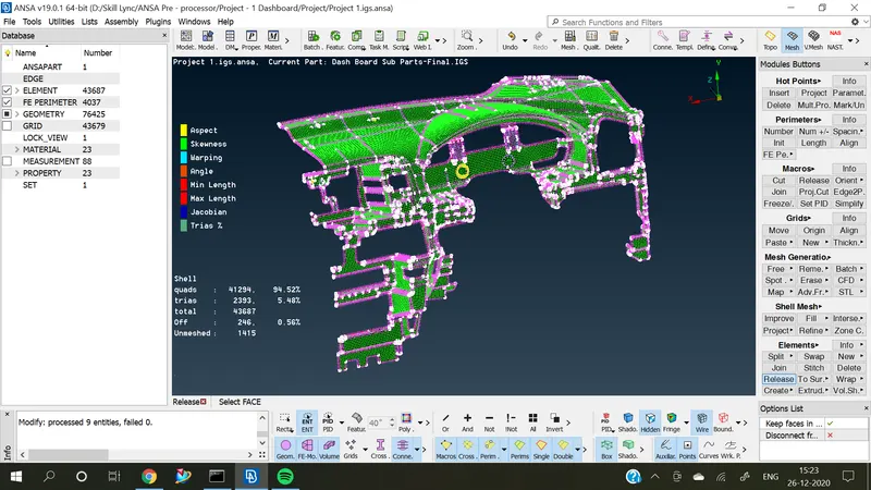
By using all this method, we have to make the mesh and resolve the error as much as possible.
CONCLUSION:
The Meshing has been successfully deployed on the instrumental panel as per the industry based quality parameters.
Learning outcome:
- The complete process of Mid surfacing.
- Learn how to perform meshing on big components.
- How to resolve the large no. of issues are created while doing meshing.
Google Drive link:
https://drive.google.com/file/d/1njBtnFOaBiqUBfPb6w7q_H12nJwvCN-W/view?usp=sharing