Project 1
Aim: To design the Main frame with Lean (Grid-2) & Gable frame without Lean (Grid-15) of the Proposed Coil center is to be modeled and designed with given data.
Given Data:
a. Building Parameters
-
Building Width = 30000.00 mm
-
Width Module = Clear Span
-
Building Length = 140000.00 mm
-
Building Height = 11100.00 mm
-
Roof Slope = 1:10
-
Column Base = Fixed Base
-
Bay Spacing (in mm)
-
Main frame with Rafters = 14@10000
-
Roof Bracing = Diagonal Angle Bracing
-
Wall Bracing = Portal Bracing and above Angle Bracing
-
End Wall Type = Rigid Frame
-
Assume Purlin Load (in kg/m) = 8.77
-
Assume Gantry Girder Weight (in kg/m) = 158.24
- Assume Rail Weight (in kg/m) = 53
-
Assume Purin Load (in kN/m) = 0.0860337
-
Assume Gantry Girder Weight ( in kN/m) = 1.5523344
-
Assume Rail Weight (in kN/m) = 0.51993
b. Load and Design
-
Assumed Dead Load (in kN/m2) = 0.14
-
Coil Load (in KN/m2) = 0.15
-
Live Load (in kN/m2) = 0.75
-
Wind Speed (in kmph) = 180
-
K1 = 1
-
K2 = 0.94
-
K3 = 1
-
K4 = 1.15
-
Building Condition = Medium Permeability
-
Seismic Zone = Zone III
Procedure:
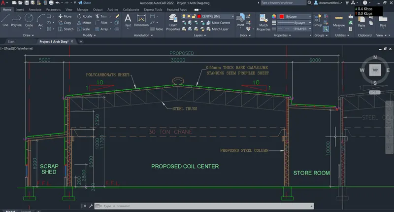
Step 1: Open the attached CAD file. The Proposed Coil Center Sectional View is as shown in the below figure.
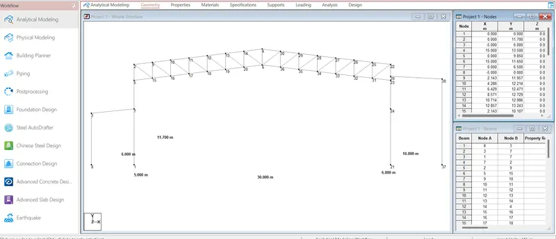
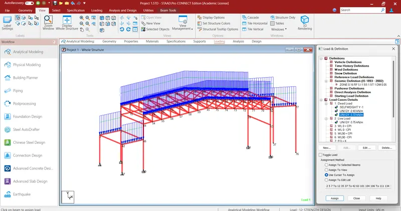
Step 2: Now, we will add the loading cases for the modeled frame.
Calculation of Dead load on rafter & column= 0.14 kN/m2
= 0.14x10 =1.4 kN/m
Purlin Load = 8.77 kg/m = 87.7 N/m
= 87.7x10 N = 877 N
= 0.877 kN
Assuming Weight of Roof Sheeting (0.55 mm Galvanized sheet)
= 5 kg/m2 = 0.05 x 10 = 0.5 kN/m
Assuming weight of sag rod, Bracings, Clips etc. = 5.75 kg/m2 = 0.0575 x 10 = 0.575 kN/m
Total Dead Load = 1.4 + 0.5 + 0.575 = 2.475 kN/m
Live Load = 0.75 kN/m2 x 10 = 7.5 kN/m
Collateral Load = 0.15 kN/m2 x 10 = 1.5 kN/m
Total Dead Load on Lean to= 2.475/2 + 1.5 kN/m = 2.736 kN/m ( As bay spacing= 5 m & collateral load 1.5 kN/m)
Live Load on Lean to = 3.75 kN/m ( As bay spacing=5 m)
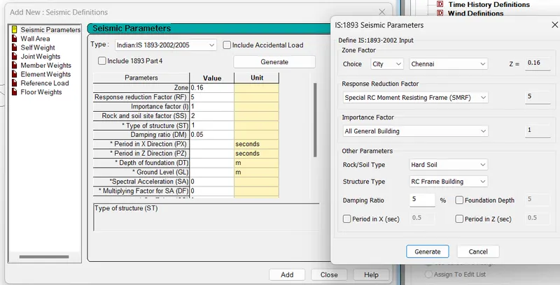
Step 3: Now Applying Seismic Load Calculation. The seismic definition then defines Seismic parameters as follows-
- First selecting IS 1893-2002/2005
- For Chennai , zone factor (Z) = 0.16 for zone-3
- Response Reduction factor = 5 for SMRF ;
- Importance factor =1 (For general Building) ;
- Soil type =2 (Considering soil as medium soil)
- Structure type =1 ; Damping Ratio =0.05
- Click on Generate Button, all parameters are available as shown below.
Step 4: Calculation for Crane Load.
Crane capacity: 30 MT ( EOT Crane)
c/c of crane rail: 27.41 m
Crane height: 7.5 m
Crane wt including hoist: 35 MT
Gantry Girder weight: 158.24 kg/m
Rail weight: 53 kg/m
No of Wheels: 4
Wheel Base: 5.8 m
Bumper Distance: 6.2 m
Maximum wheel Load: 262.00 kN
Vertical impact: 25% As per IS 875
Lateral impact: 20% As per IS 875
Longitudinal impact: 10% As per IS 875
Max. wheel load ( Vertical) = [ 35/2 + 30]/2 =23.75 MT = 237.5 kN
Dead load of Rail and Gantry Girder = (158.24 + 53 ) kg/m =211.24 kg/m
= 2.11 kN/m = 2.112x10 = 21.12 kN
Vertical load on each Bracket = 10.56 kN
Max Reaction on Crane Bracket Rmax with a Dead load of Rail & Gantry girder
= 237.5+ 10.56 = 248.06 kN
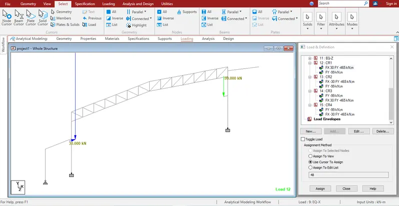
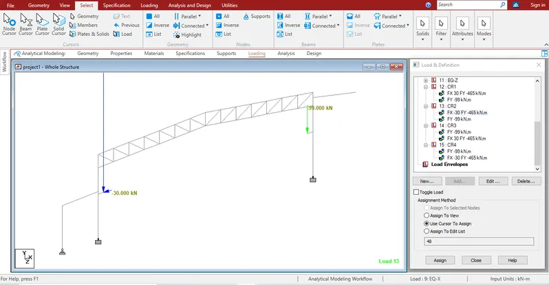
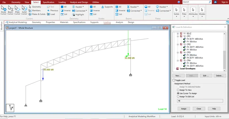
Min. Reaction on the Bracket Rmin = 0.4 x 248.06 = 99 kN
Horizontal wheel load transverse to rails = 0.2 x 30/2 = 3 MT = 30 kN
( 20% as per given input but as per IS 875 part-2 Clause 6.3.2 it is 10%)
Max Reaction on the Bracket with Impact of 25% as per IS 875/ Part-2, clause 6.3
Rmax = 1.25x 248.06 kN = 310.075 kN
Design vertical load with F.S = 310.075x 1.5 = 465 kN
Rmin = 99 kN
Case 1) Rmax on left Bracket, +H on Left Bracket, Rmin on Right Bracket
Case 2) Rmax on left Bracket, -H on Left, Rmin on Right Bracket
Case 3) Rmin on the left Bracket, +H on the Right Bracket, Rmax on Right Bracket
Case 4) Rmin on left Bracket, -H on Right Bracket, Rmax on Right Bracket
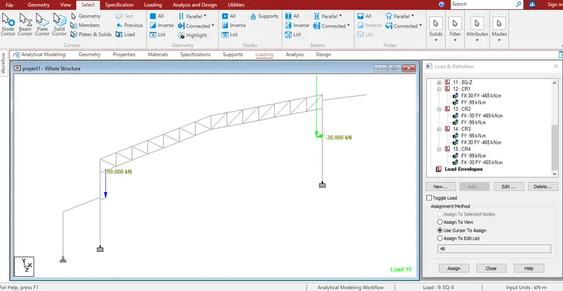
The application of load for the various cases has been shown in the above figures:
Horizontal traction force along the rails = 0.1 (262.5+262.5) = 52.5 kN
( 10% as per given input but as per IS 875 part-2 Clause 6.3.2 it is 5%)
Step 5: Calculation of wind pressure
Design wind speed = Vb x k1 x k2 x k3 x k4.
= 50 x 1 x 0.94 x 1 x 1.15.
= 54.05 m/s.
Wind pressure = 0.6 x 54.05^2 = 1.75 KN/m2.
As per IS 875 Wind direction factor kd = 1
Area averaging factor ka = 0.83 .
Combination factor kc = 0.9
Design wind pressure = 1.75 x 1 x 0.83 x0.9= 1.307 KN/m^2.
Wind load = 1.307 x 11.1 = 14.50 KN/m.
0 + CPI = 14.50+ 0.5 - 0.9 = 14.10 KN/m.
14.50 + 0.5 -0.4 = 14.6 KN/m.
0 - CPI = 14.50 - 0.5- 0.99=13 KN/m.
90 + CPl = 14.50 + 0.5 - 0.8 = 14KN / m .
9O - CPI = 14.50 - 0 -0.8=13.2 KN/m.
14.50 - 0.5 - 0.4 = 13.6 KN/m.
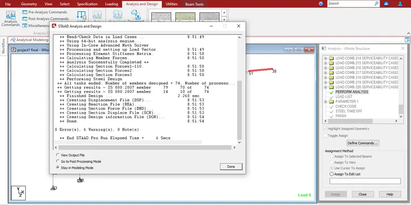
Step 6: Now run the analysis to check if there is any error occurring, if not then the Structure has been successfully designed.
The analysis is done with zero errors as shown below.
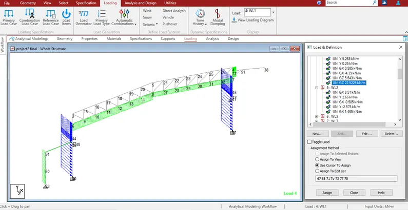
Step 7: Gable frame is also analyzed with load intensity of 50% (Dead load, live load, and wind load only) of Mainframe
Wind load in Z direction due to gable frame is shown in the below figure.
The run analysis is also performed for the Gable Frame with Zero Error as shown below:
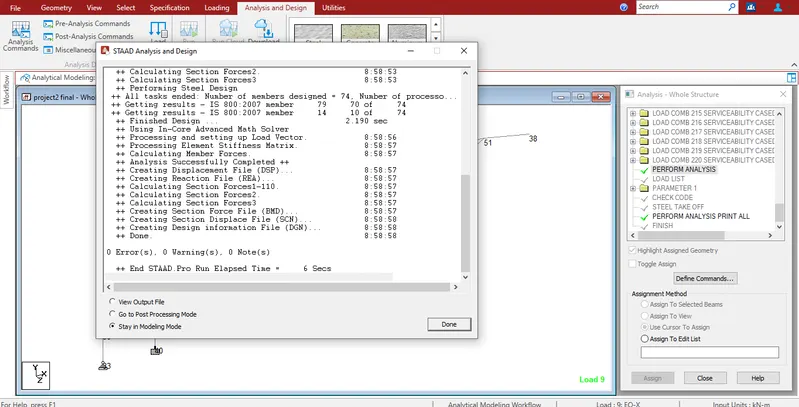
Result: Model has been successfully modeled in the STAAD Pro, for the given data. Run analysis has been performed successfully with zero errors.