Project 1
AIM:
To create better mesh by applying given quality criteria parameters on the given plastic model and assigning proper thickness to the model.
OBJECTIVE:
Make proper geometry cleanup before going to extract the midsurfaces of different components in the given model, After that go for meshing by setting given quality criteria parameters and correct the failed elements, By using quality criteria tools. Finaly assign the thickness to all the components in the given model.
GIVEN MODEL:
*Given plastic model is varying thickness along the component and it has ribs with different thickness.
*Given Component is shown in below figures with and without performing TOPO operation.
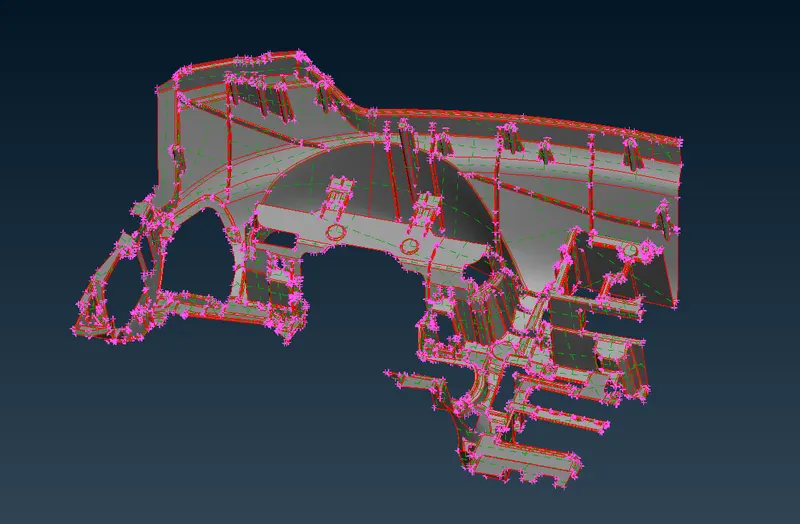
Before TOPO Fig(1).
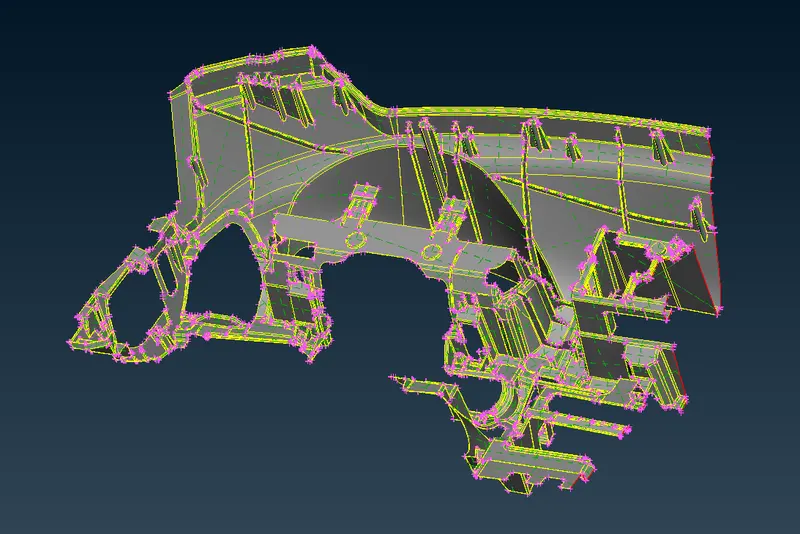
After TOPO Fig(2).
PROCEDURE:
1.The Ansa software supports the generic CAD formats i.e( STEP,IGES,STL).
2.Import the cad geometry which is in any off above format in ansa by using open option by, selecting the File >> open.
3.Observe the geometry carefully and notice that geometry has any symmetrical faces, thriple cons, single cons etc.
4.To identify above mentioned geometric issues we have to use Checks option in that click on Geometry to open the Geometry checks manager tab as shown in below Fig(2).
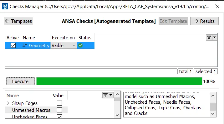
Geometry Manager Fig(3).
5.Above Fig(3) shows that the geometry does not have any geometrical errors. since it has executed upto 100 percentage.
6.Once geometry checks completed then extract the 'mid surface' either using midsurface option or 'offset' option.
7.Mid-surface option is used mostly in sheet metal operations because they have constant thickness throught the component.
8.Offset option used in both constant thickness and varying thickness components, but mostly used in plastic components due to varying thickness.
9.In this model since it is a plastic component which is varying thickness along the component. I used offset,middle,multi middle option to extract the mid-surface of component by, Selecting the TOPO >> Faces >> offet (or) middle.
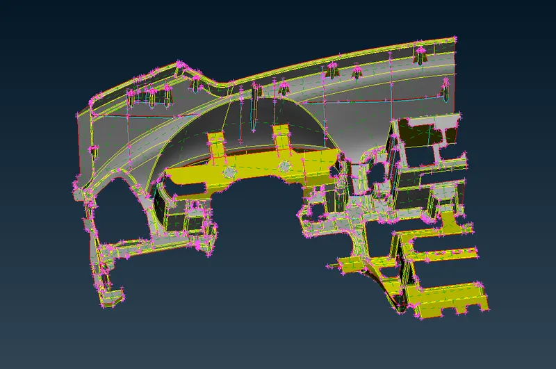
Mid-Surface using Offset Method Fig(4).
10.If we observe the above Fig(4) we can find all the ribs and different components all those components are have different thickness.
11.After creating all the mid-surfaces for the parts in the component, then start meshing.
12.After completing the geometry cleanup we can create the Quality criteria parametre file and mesh parametre file as shown in Fig(5) and Fig(6).
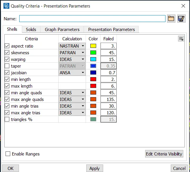
Quality Criteria File Fig(5).
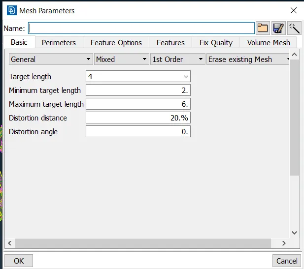
Mesh Parameter File Fig(6).
13.Before start the mesh assign the length value equal to average element length in parameters panel in TOPO module By, Selecting TOPO >> parameters >> length.
14.Perform the mesh using the Best or spotmesh options in Mesh Generation panel in MESH module by, Selecting the Mesh >> Mesh Generation >> Best.
15.Perform the mesh operations and eliminate the off element by using Reconstruct,smooth ,split and different options.
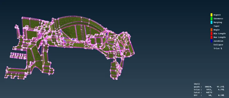
Fig(7).
16.In above Fig(8) we can see clearly the unmeshed surfaces,off elements ,trias,quads,tria percentage etc.
17.Once after completing the mesh on the component make sure there are no off elements and unmeshed surface with proper feature capturing.
18.The complete mesh on the plastic model with having zero off elements and unmesh surfaces.
19.Similarly i performed same procedure for other components in the given Model.
20.To assign varies thickness we have to create varies PID's and apply those components to particular PID.
THINGS LEARNT IN THIS CHALLENGE
1.Creating mid-surface for thickness varying components like ribs,teeth,threads etc.
2.removing off elements and unmeshed surfaces with proper feature capturing.
CONCLUSION
1.Taking Mid-surafce for thickness varying components using mid-surfaace option i.e( auto mid-surface ) wiil lead to create bd results.
2.Manual mid-surface is the best method to generate the mid-surface for such components to get more approximate results.
RESULTS
*The Final Results shown in below Fig (8) Different color component shows that they belongs to different PID's.
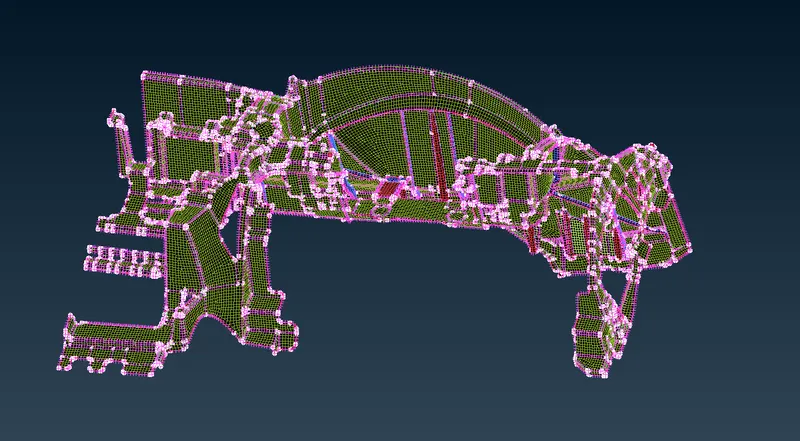
Final Image Fig(8).