REVIT 3D Rendering of a house plan_Project 1
1)
Aim: To create a ceiling above the walls of the first floor.
Tools used:
- file
- open
- project browser
- architectural tab
- ceiling
- pick lines
- offset
Procedure:
- open the revit file from the file menu
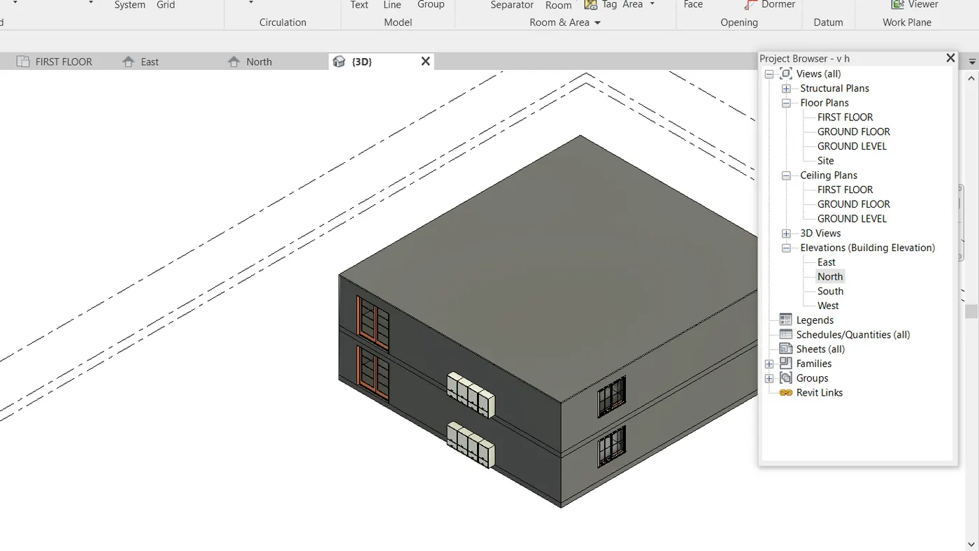
- then from the project browser open the first floor plan from the floor plans tab
- after opening the first floor select the ceiling icon from the architectural tool bar.
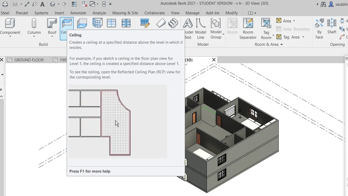
- from the modify panel select the pick lines/walls icon to adjust the boundaries of the ceiiling.
- and lastly to adjust the ceiling to the walls properly set up the offset from the properties bar.
Result: The ceiling to the first floor above its walls is clearly adjusted.
2)
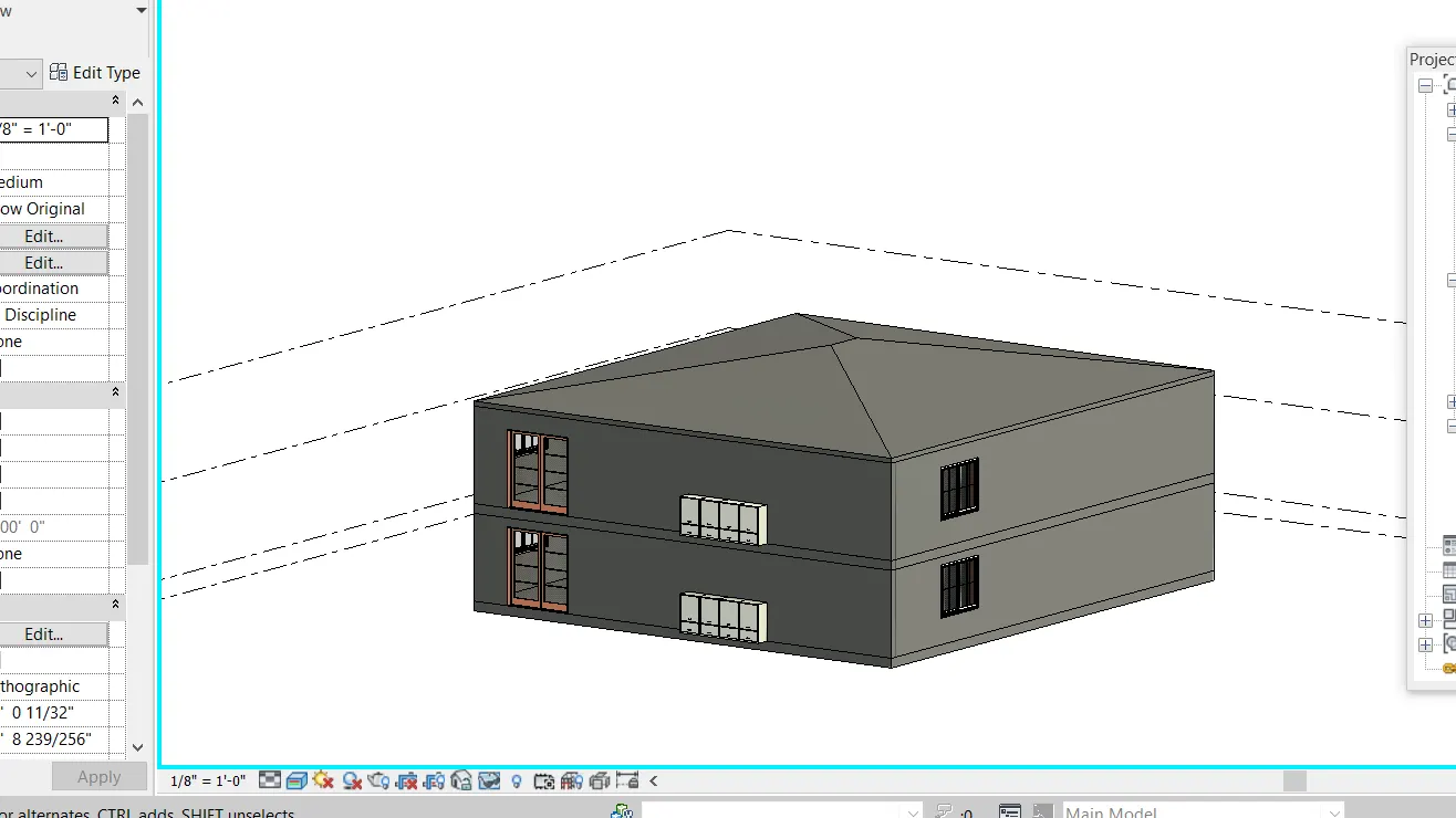
Aim: To create a roof above the ceiling and adjust the slope of the roof to 10°.
Tools used:
- file
- open
- project browser
- architectural tab
- roof by footprint
- project units
- modify
- attach the top .
Procedure:
- Firstly open the revit file using the file menu.
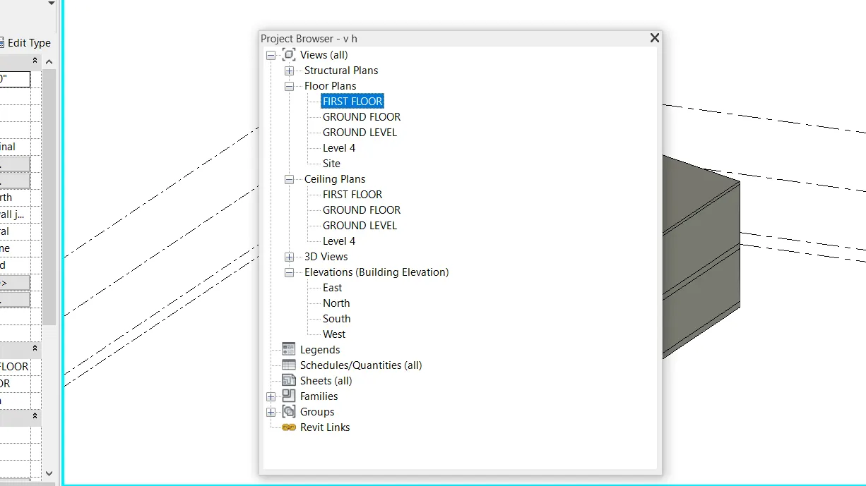
- then from the project browser open the first floor plan.
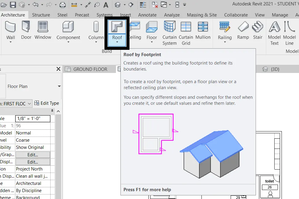
- from the architectural tab select the roof by footprint property.
- then choose the pick lines property from the modify panel and select the boundaries of the ceiling to adjust the roof properly.
- complete the roof by choosing the finish icon (green tick mark).
- then to adjust the slope initially from the manage menu select the project units andadjust the slope units to degrees.
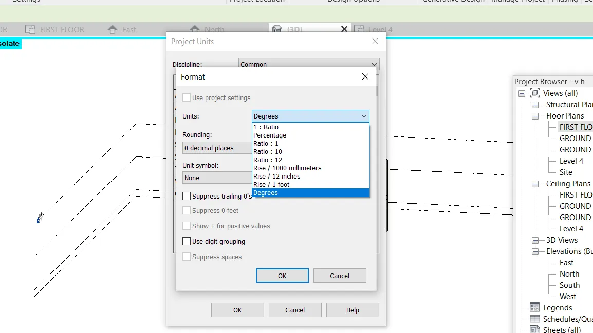
- then as per the requirement of the question select the slope as to be 10 degrees from the properties panel.
Result: roof on the walls above the first floor is properly adjusted with slope of 10 degrees.
3)
Aim: To create plan views for the files saved.
Tools used:
- file
- open
- view
- plan views
- floor plan
- wall
- insert
- load family(for components)
Procedure:
- Open the previously saved file from the file tab and click on open.
- then from the quick access tool bar above slect the view category .
- there you willl find the plan views icon
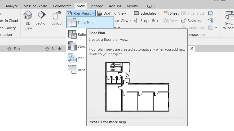
- select the plan views icon and choose floor plan from the options and continue by clicking ok.
- then the ground floor/level 1 floor plan appears.
- by the use of wall property draw place the layout accordingly .
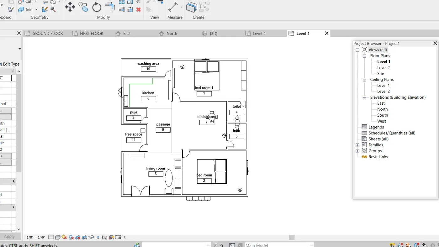
- from the insert tab use load family to load certain family elements and then pace them in the drawing.
- do the same with the level 2 and finish the layout properly.
Result: floor are successfully drawn in the plan views with attaching the components as well.
note* : either the structural plans or the templates were not covered in the 4 weeks this is submitted exceptioning the structural plans.
4)
Aim: to add diemensions to the drawing between the components and the walls.
Tools used:
- file
- open
- grids
- annotate
- align
Procedure:
- open the revit file from the file menu
- then open the drawn groun/first floor plan from the project browser
- then select the grid property from the architectural plan.
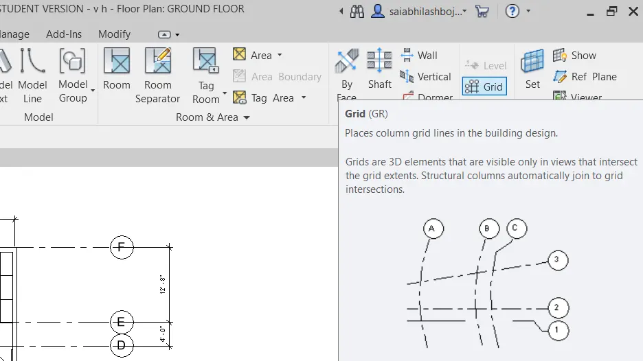
- And draw the grids according to the need between the components and the walls.
- use the annotate bar and select the aligned property
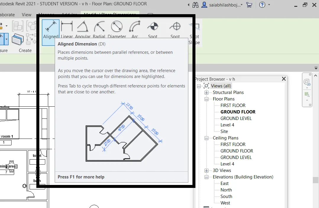
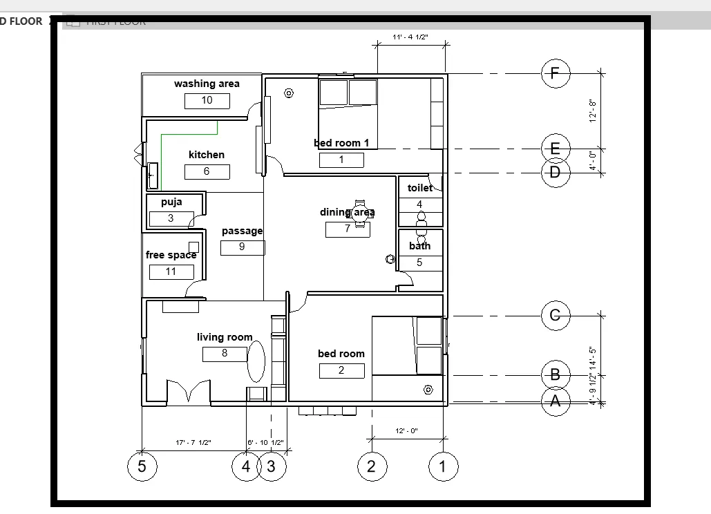
- then using the aligned property measure the dimension between the walls and the components.
Result: using the align property the dimensions between the components and the walls are drawn represented with grids
5)
Aim: To make a sheet and change its parameters.
Tools used:
- file
- open
- view
- sheet
- load
- properties
Procedure:
- open the revit file
- and then to create a sheet in the file choose view tab
- then choose the sheet property to create a new sheet
- to find varieties of sheets we can choose from title blocks.
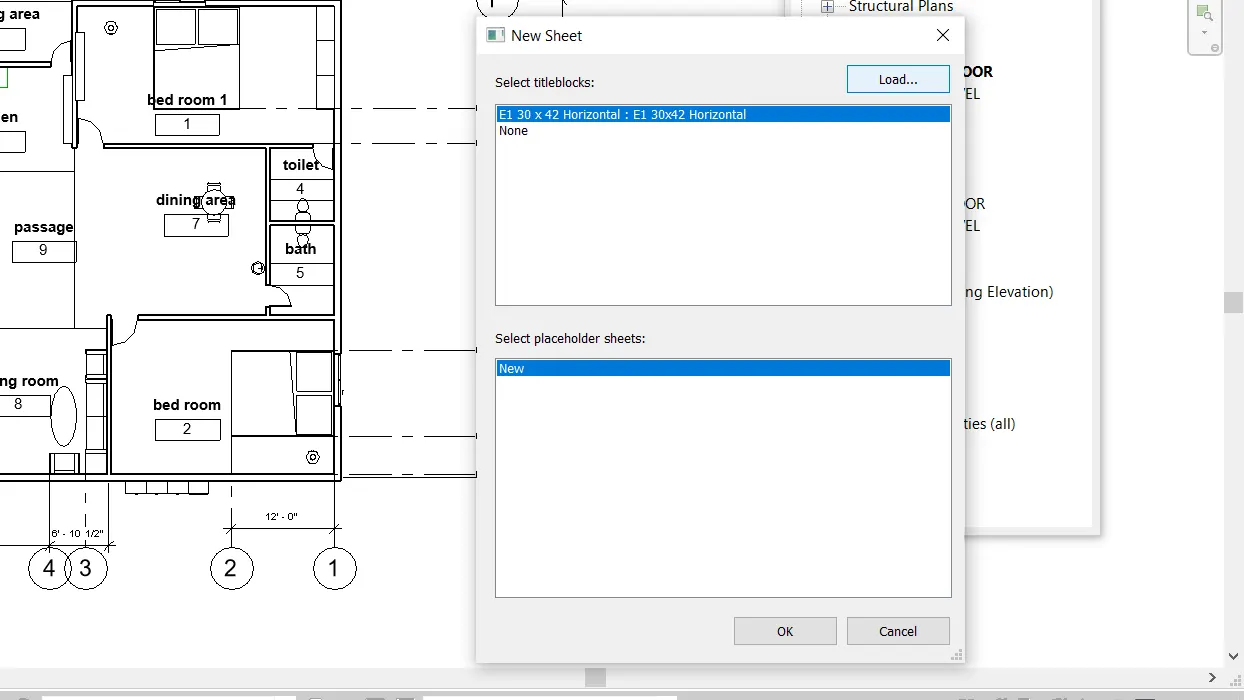
- a sheet with default size already exists but if you want sheets of different sizes you can load and select the appropriate sheet.
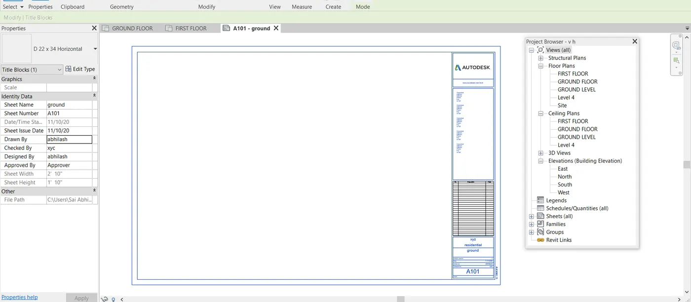
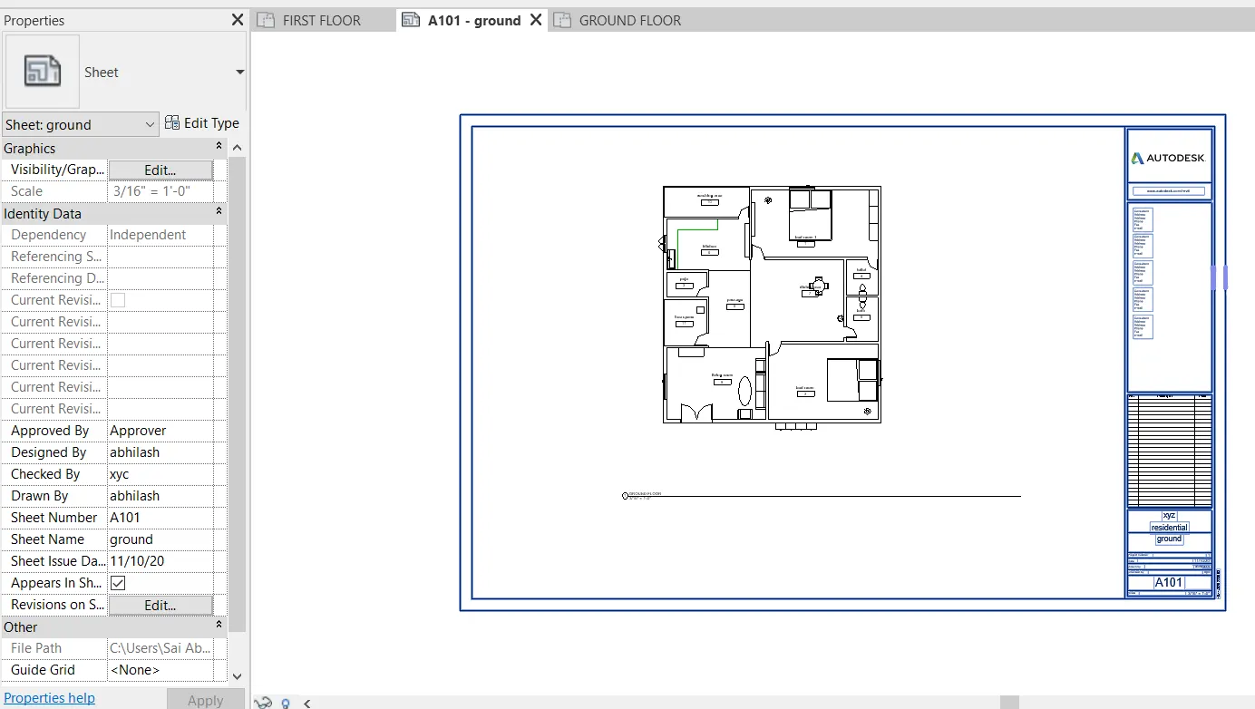
- then use the properties the pannel to change the parametres such as owner,designer,approved by and etc.,
- for an alternative you can directly change the sheet parametres in the sheet.
Result: A sheet is created and its properties are edited as required.
6)
Aim: using the elevation and create different elevation views i.e., north,south,east,west.
Tools used:
- file
- open
- view
- elevation
- setting the elevation
- project browser
- rename
Procedure:
- open the file
- select the access bar select the view task bar
- from that select the elevation property.
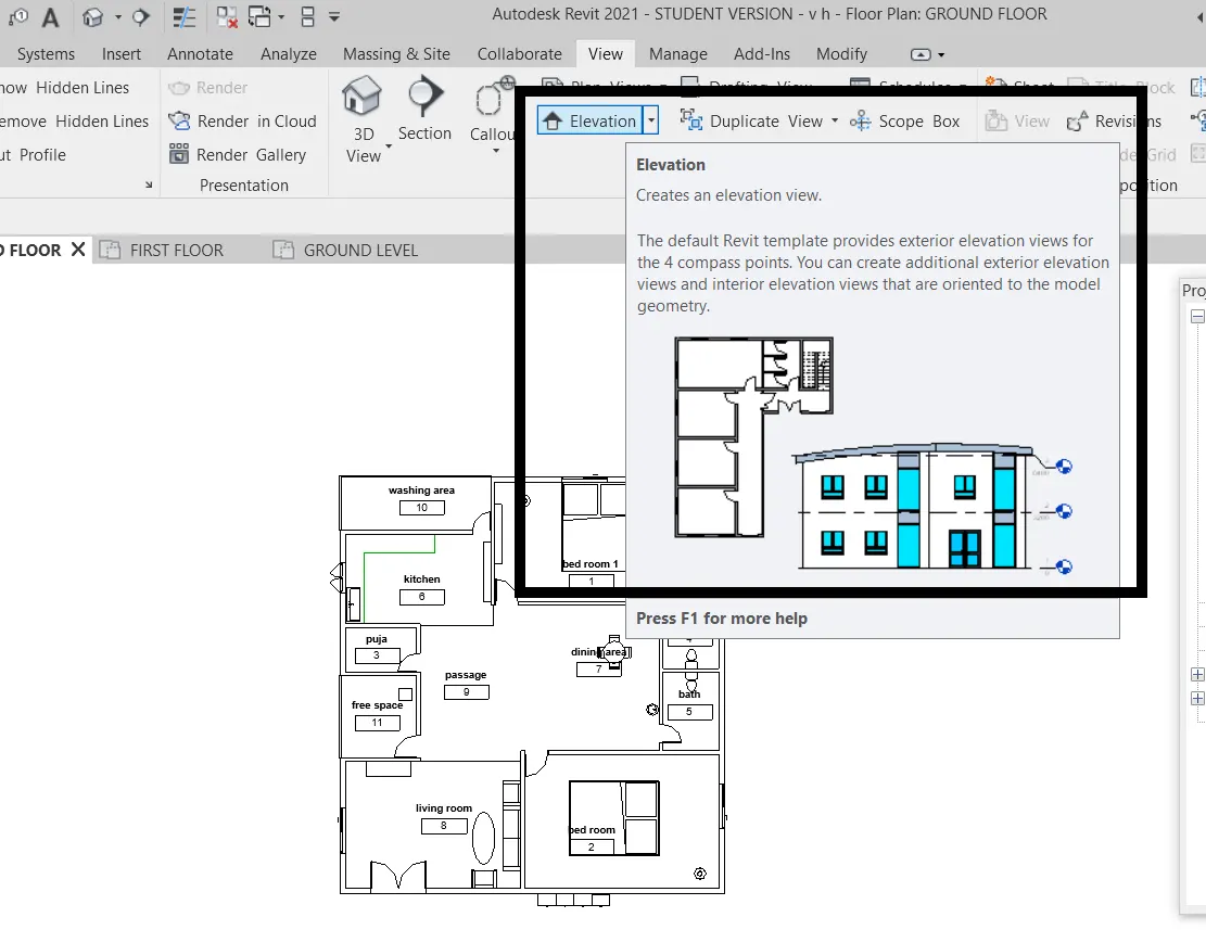
- with this we can set the elevations in different directions in reference to the cameras or viewing points.
- place the point of elevation appropriately so that while viewing it is clear and we can also adjust the boundaries of the elvations by opening the elevation.
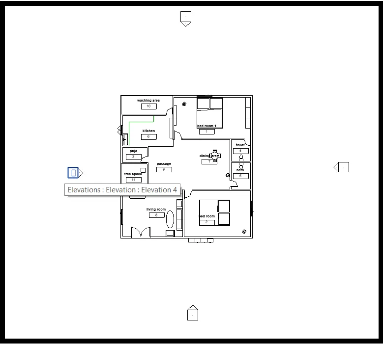
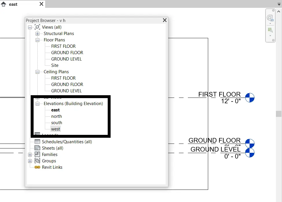
- now from the properties rename the elevations as respectively i.e., north,south,east and west.
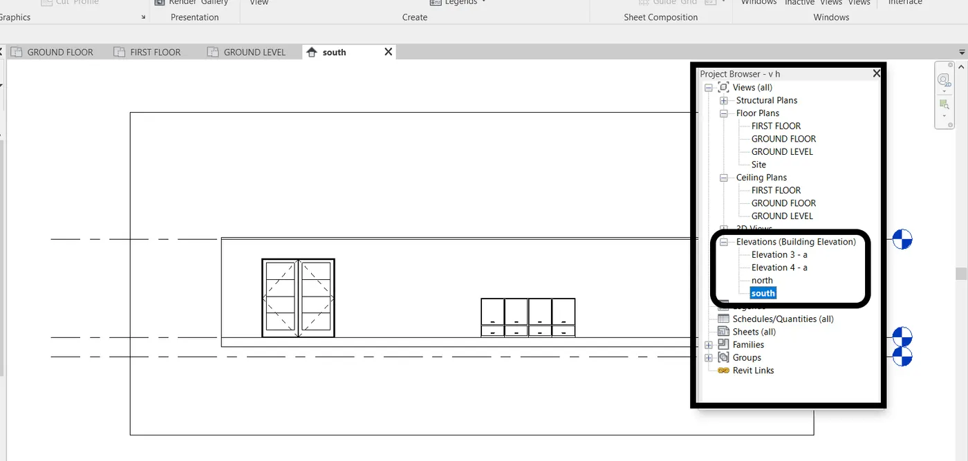
- for an alternative you can also rename them from project browser by selecting and editing the name.
Result: The required elevations are created and named properly.
7)
Aim: To make section cuts throough all the rooms.
Tools used:
- file
- open
- view
- section
- section adjustment
- properties
- rename
Procedure:
- firstly open the revit file
- from the view bar select the section icon.
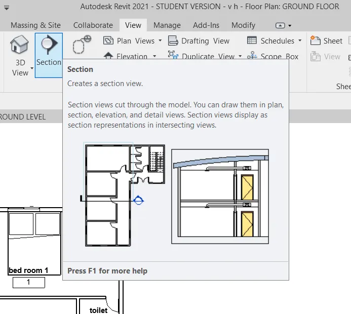
- after that select the area or the region of the required section view.
- as of the question we need to set the section at every room either in longitudinal or in traverse.
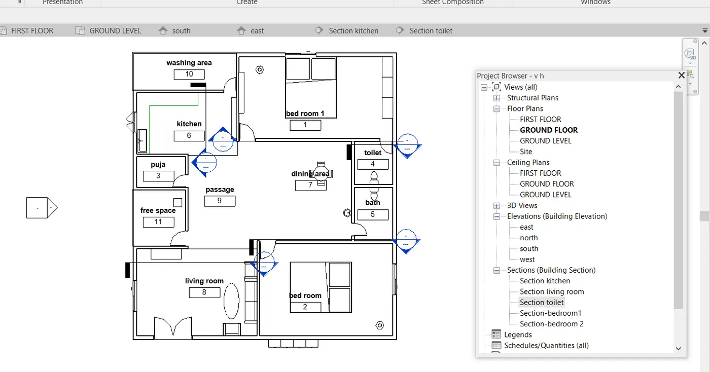
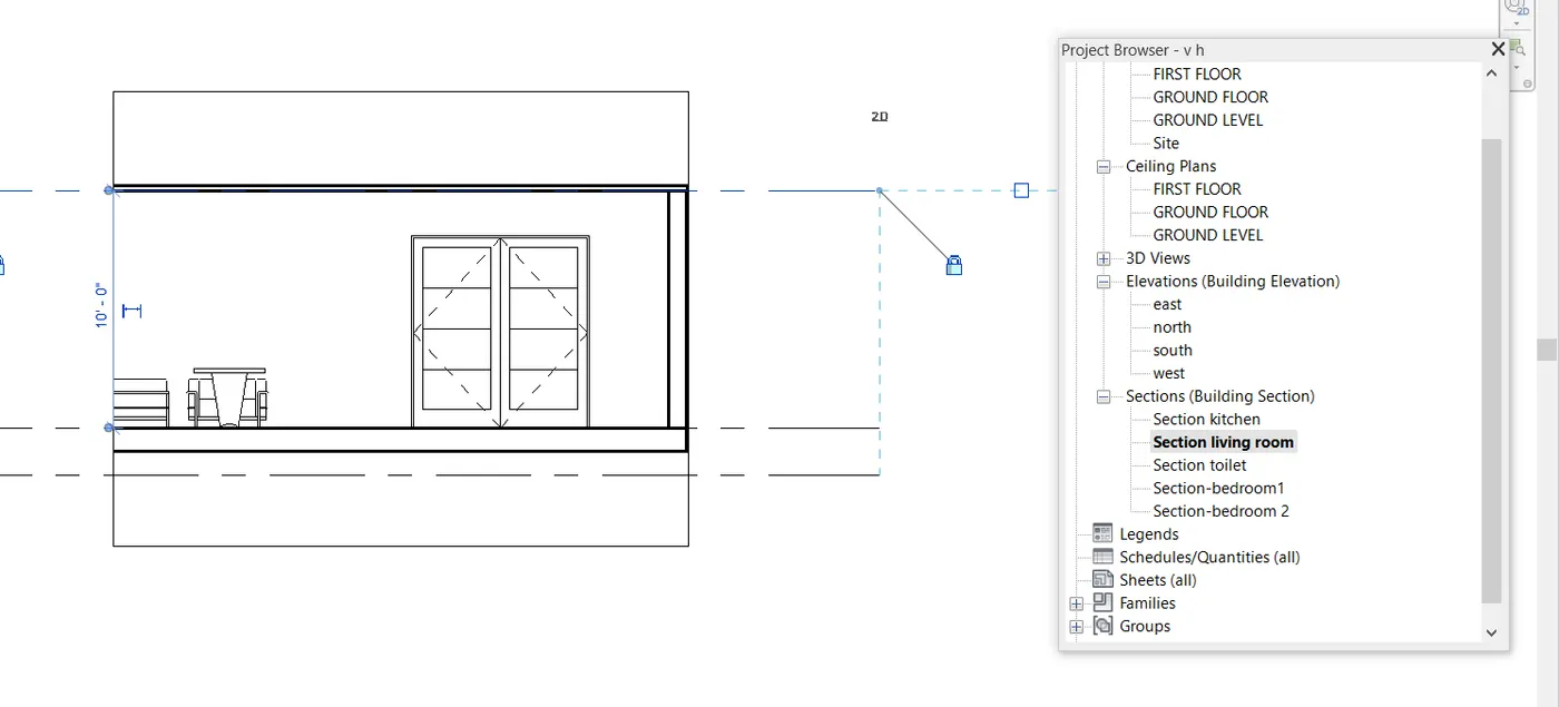
- as from the above picture we can clearly see that section is made through different directions in several rooms.
- as we make sections in the drawing the project browser eventually gets updated with a sepearte tab of sections
- and so to view or rename them we can use the project browser
Result: Sections are made clearly between the rooms and sectional views are available in the project browser.
example for a sectioanl view of livimg room:
8)
Aim: To classify the views into design and documentation category using project browser.
Tools used:
- File
- open
- project browser
- browser organization
- design and documentation
Procedure:
- firstly open the revit file
- and from the project browser select the view tab
- Cick on the view tab and select browser organization from that
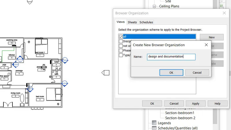
- Now click on new and dediacte it as design and documentation
- finally click on ok.
- Now you can see all of the views in design and documentation category.
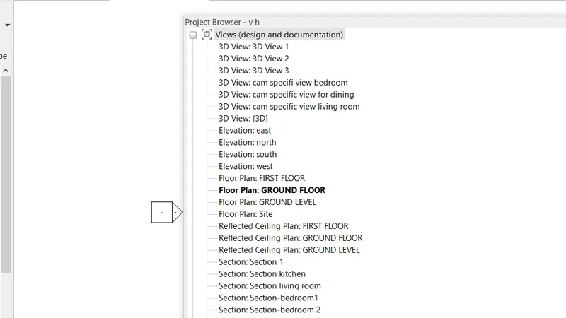
Result: all the views are classified to design and documentation category.
9)
Aim: To create several sheets and place floor plan and elevations on to the sheets.
Tools used:
- file
- open
- view
- sheet
- project browser
- properties
- rename
Procedure: .
- open the previously saved revit file
- From the view tab select the sheets property.
- A sheet will be produced by default size if you want different size just go tto title blocks and select the size of the sheet .
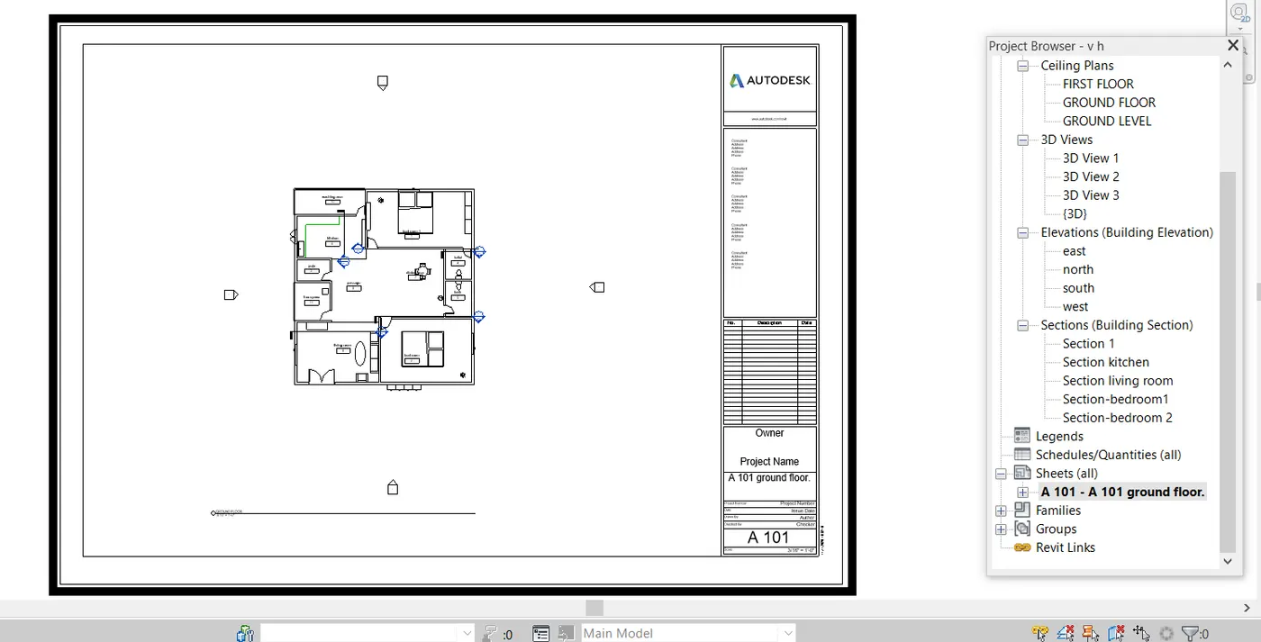
- A 101 Ground floor architectural paln
- on the sheet produced, select the ground floor plan from the project browser and drag it on to the sheet.
- and then adjust the size of the layout as required from properties.
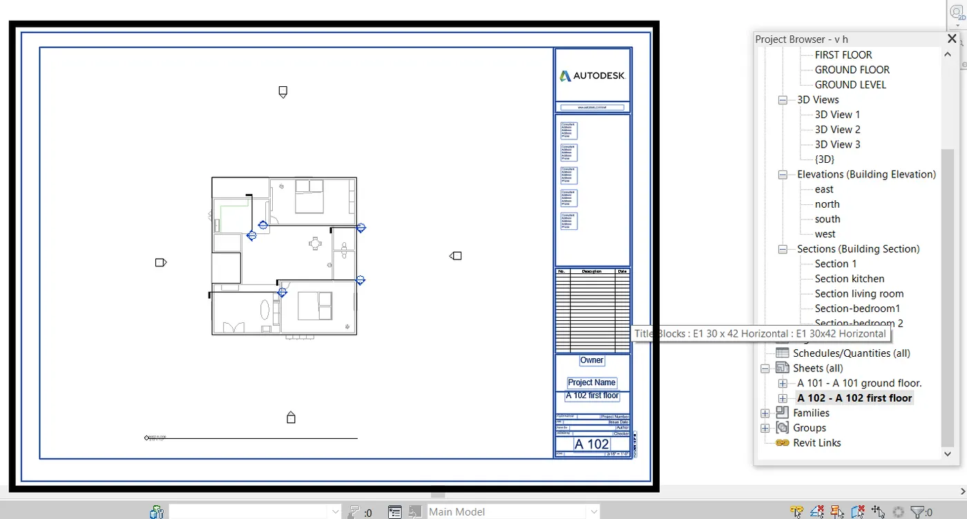
- A 102 First floor architectural plan
- open a new sheet and then from the project browser drag the first floor plan on to the sheet and place it .
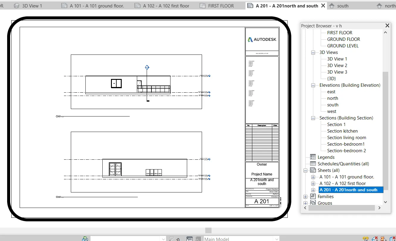
- A 201 North south elevations
- open another fresh sheet and from the project the place the plans of north and south elevations on to the sheet.
- A 202 East West elevations
- Now on a newly created sheet drag both the elevations of east and west and place them on the sheet adjusting the sizes.
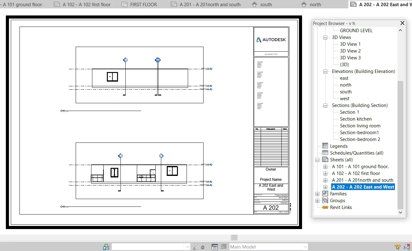
Result: Thus the required sheets are made successfully and also the numbers of the sheets are represented accordingly.
10)
Aim: To create a 3d view using camera property in different rooms and create new set of sheets based on those views.
Tools used:
- file
- open
- view
- 3d/camera
- project browser
- sheet
- properties
Procedure:
- from the file window open the saved file.
- from the view tab seclect the camera option from the 3d view section
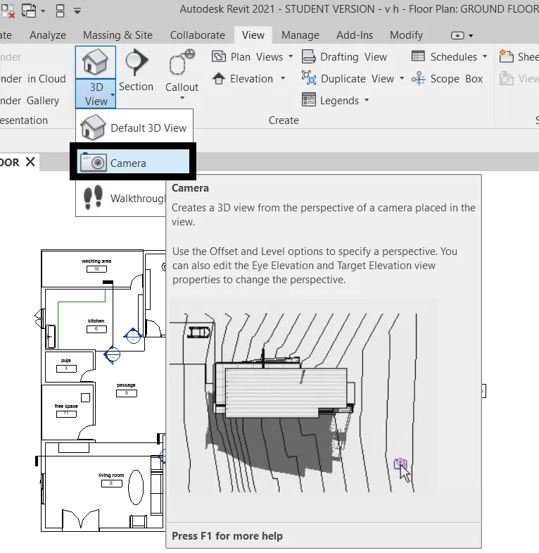
- then place the camera and its reach accordingly to the required view.
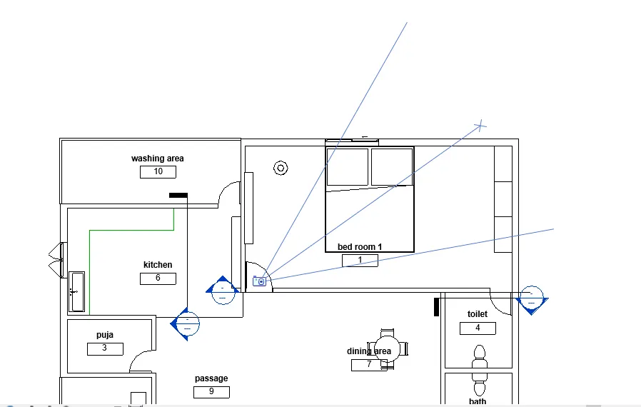
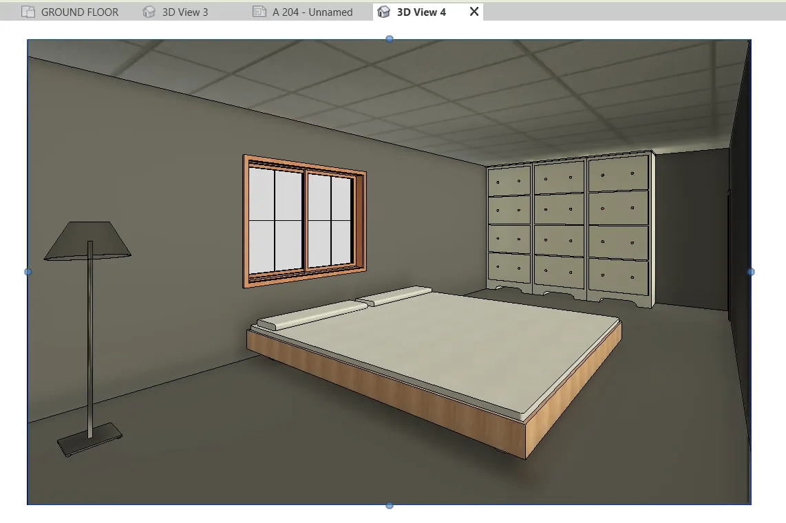
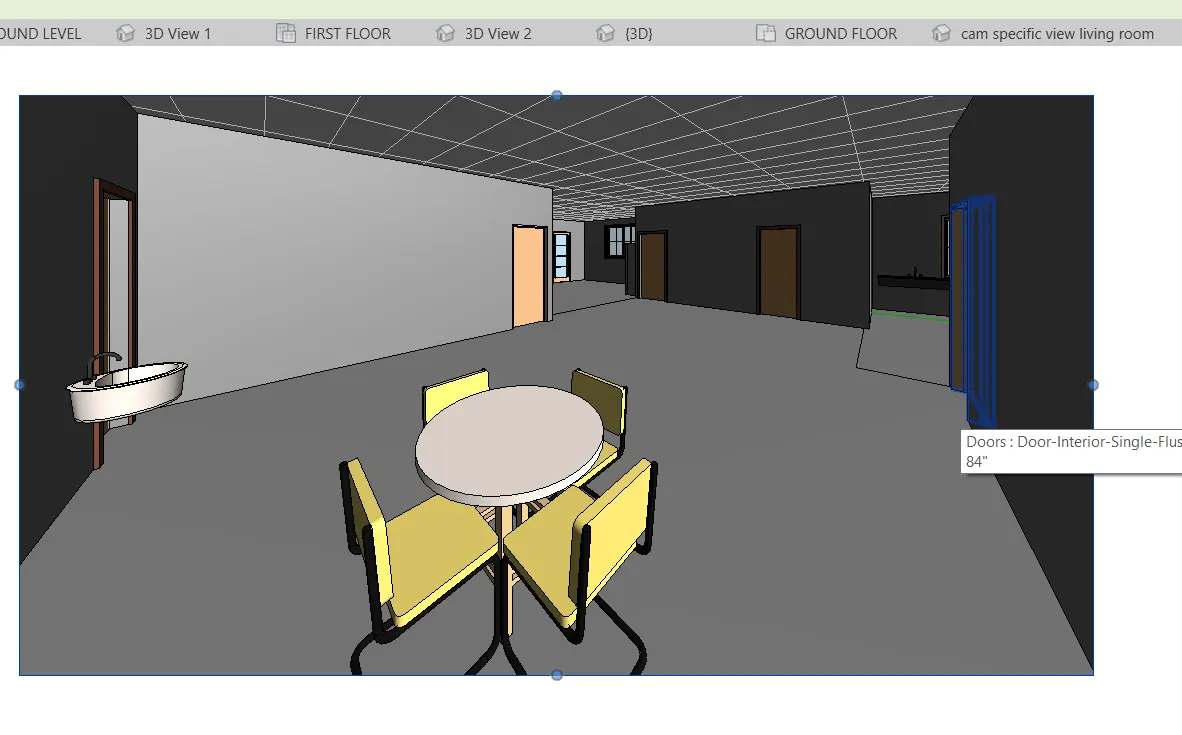
- then a camera specific view will be created according to the coverage of the camera view.
- camera specific view for 'bedroom'
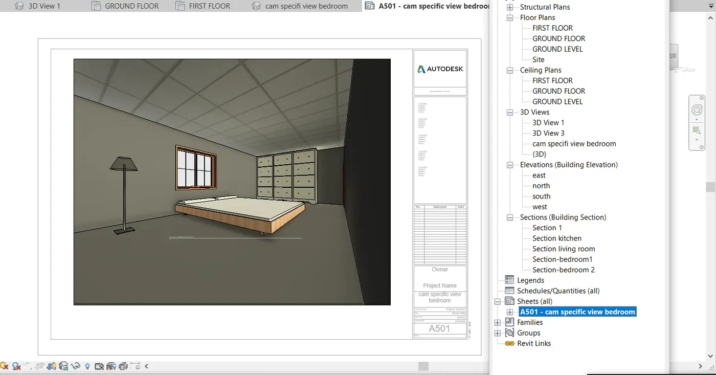
- A 501 sheet for camera specific view of bedroom
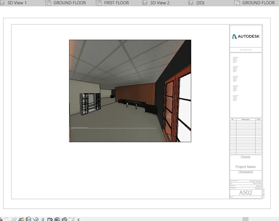
- Cam specific view for living room
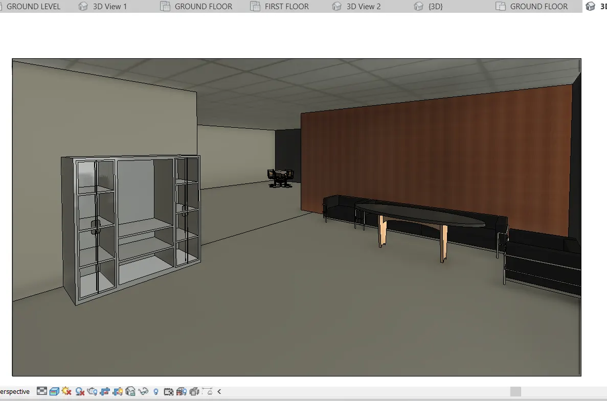
- A 502 sheet for cam specific view of living room
- cam specific view for dining
- A 503 for cam specific view of dining
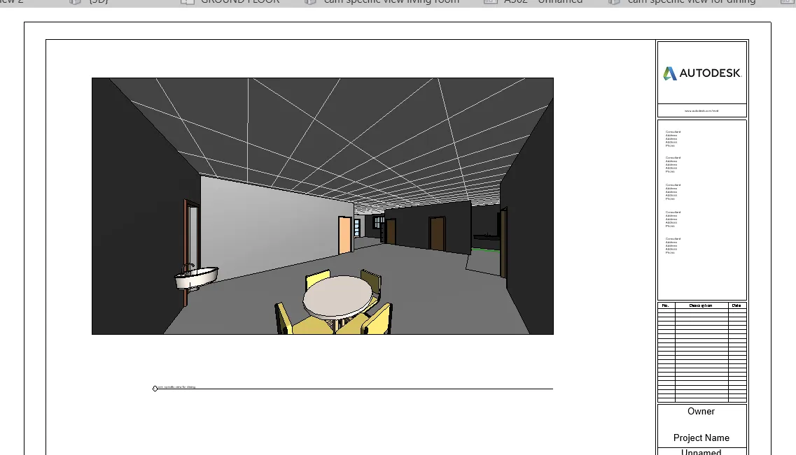
- similarly using the same process sheets are created sequentially for the cam specific views of kitchen,puja and etc.,
Result: The sheets for the respective cam specific views are created for several rooms and starting with the sequential order A501.