Project 1
Aim - To design a multi-storey Residential Building located in Bangalore using STAAD Pro Connect Edition.
Procedure -
DBR - Design Basis Report -
Step 1) Given data -
|
Building floors |
G + 6 + R |
|
Plan dimension |
B = 25m , L = 16m |
|
Storey Height |
h = 3.5m |
|
Soil |
Hard soil |
|
Use |
Residential Purpose |
|
Safe Bearing Capacity |
180 kN/m2 |
|
Maximum slab thickness |
150mm |
Step 2) Creating Geometry of the Model
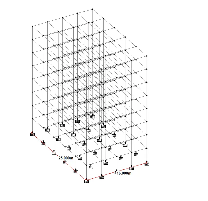
i) Create the geometry of the model
ii) As it is Residential Building and it has following dimensions
iii) L = 16m
iv) B = 25 m
v) H = 30 m
vi) Once geometry is created assign support condition as Fixed
Step 3) Material Specification
i) Assume the size of beams - 0.300 x 0.450 m
ii) Assume the size of columns - 0.500 x 0.500 m
Step 4) Loads
Calculation of Loads -
1) Calculation of Dead Load - IS 875 part 1
i)Dead load on Floor
i) Dead load due to slab = 0.150 x 25
= 3.750 Kn/m2
ii) Partitions = 1.5 Kn/m2
iii) Floor Finish = 2.5 Kn/m2
iv) Miscellaneous = 1 Kn/m2
v) Total Floor Load = 8.75 Kn/m2
ii) Dead load on Roof
i) Dead load of Roof Slab = 3.75 Kn/m2
ii) Insulaions and Water Proofing = 0.5 Kn/m2
iii) MEP Services = 0.5 Kn/m2
iv) Miscellaneous = 0.5 Kn/m2
v) Total Roof Load = 5.25 kn/m2
2) Live Load - IS 875 part 2
i) For Residential Building LL = 3 Kn/m2
ii) For Roof = 1.5 Kn/m2
3) Calculation of Wind load
i) Design Wind Speed
We know that
Vz = Vb x k1 x k2 x k3 x k4
where ,
Vb=Basic wind speed (m/sec)
K1=Risk coefficient (Table 1 of IS 875 (Part 3)-2015)
K2 = Terrain Roughness and height factor
K3=Topography factor (Clause 6.3.3 of IS 875 (Part 3)-2015)
K4 =Importance factor for Cyclic Region
AS Vb = 33 m/s ( Darjeeling ) Is 875
K1 = 1
K2 = 1.15 ( Ht for 30m) ( Category 1)
K3 = 1
K4 = 1
Therefore ,
Vz = 33 x 1 x 1.15 x 1 x 1
= 37.95 m/s
ii) Wind Pressure = Pz
Pz = 0.6 x Vz ^2
= 0.6 x 37.95 x 37.95
= 864.121 N
= 0.864 Kn
Similarly we can calculate for different heights
| Height (m) | k2 | Vz (m/s) | Pz | Pz in kN |
| 3.5 | 1.05 | 34.65 | 720.37 | 0.720 |
| 7 | 1.05 | 34.65 | 720.37 | 0.720 |
| 10.5 | 1.06 | 35.2 | 743.424 | 0.743 |
| 14 | 1.08 | 35.64 | 762.12 | 0.762 |
| 17.5 | 1.10 | 36.3 | 790.61 | 0.790 |
| 21 | 1.125 | 37.13 | 827.18 | 0.827 |
| 24.5 | 1.13 | 37.29 | 834.32 | 0.834 |
| 28 | 1.15 | 37.95 | 864.121 | 0.864 |
4) Calculation of Seismic load
1) Design Base Shear
VB = Ah x W
where ,
Ah = Horizontal Coefficient of acceleration
W = Seismic Weight
ii) Ah can be calculated by using formula
Ah = Z/2 x Sa/g x I/R
As given building in location is in Bangalore -
a) Seismic Zone (Z) - Zone II ( 0.10 )
b) Soil condition or Soil type (Sa) - Hard Soil
c) Importance Factor - 1 ( For Residential Building )
d) Response Reduction Factor - 5 ( SMRF)
2)
i) Now we have to calculate the Sa/g ( Spctral Acceleraion cpefficient) which depends on Type of soils .
ii) For hard Soil -
Sa/g = 1 + 15 T .........................0.00 < T < 0.10
2.50 ...............................0.10 < T < 0.40
1 / T ..............................0.40 < T < 4.00
iii) First we have to calculat Time peroiod in x and y direction (20x 30m)
Tx = `(0.09h)/sqrt d`
= `(0.09X30 )/4`
Tx = 0.68 sec
Ty = `(0.09h)/sqrt d`
= `(0.09X30 )/5`
Ty = 0.54 sec
Considered Max time period i.e Tx = 0.68 sec
Therefore
Sa / g = 1/T
= 1.47
So put all the values in Ah equation
Ah = 0.10/2 x 1.47 x 1/5
Ah = 0.0147
3) Calculation of Seismic weight
i) Area of each Floor = 16 x 25
= 400 m^2
ii) Due to Dead Loads , Typical Floor = DL = 8.75 Kn/m^2
So Total Dead load of all floors = 8.75 x 400
= 3500 Kn
iii) Due to Dead Loads ,Roof = DL of roofs = 5.25 Kn/m^2
So Total Dead load of all floors = 5.25 x 400
= 2100 Kn
iv) Due to Live Loads , Typical Floor = LL = 3 Kn/m^2 ( Is 875 part 2)
But as per IS 1893:2016 If Live load is greater than 3 Kn/m^2 we have to reduced LL by 50%
Therefore reduced it by 50%
LL = 1.5 Kn/m^2
Total Live load for all floors = 1.5 x 600
= 600 KN
v) Due to Live Loads , Roof - AS per IS 1893 : 2016 Live load due to roof is neglected in calculation of seismic weight .
vi) Total Seismic Weight = W = DL + LL + DL roof
= (3500+ 600) x 7 + 2100
= 30800 Kn
4) Design Base Shear VB
VB = Ah x W
= 0.0147 x 30800
= 452.76 Kn
| Storey level | Wi | hi | Wihi2 | ki | Lateral Force | |
| (kN) | (m) | Qx | Qz | |||
| Roof | 2100 | 28 | 3214400 | 0.31 | 140.035 | 140.035 |
| 6th | 4100 | 24.5 | 2461025 | 0.24 | 108.66 | 108.66 |
| 5th | 4100 | 21 | 1808100 | 0.17 | 76.96 | 76.96 |
| 4th | 4100 | 17.5 | 1255625 | 0.12 | 54.33 | 54.33 |
| 3rd | 4100 | 14 | 803600 | 0.07 | 31.70 | 31.70 |
| 2nd | 4100 | 10.5 | 452025 | 0.044 | 19.92 | 19.92 |
| 1st | 4100 | 7 | 200900 | 0.019 | 8.60 | 8.60 |
| GF | 4100 | 3.5 | 50225 | 0.005 | 2.26 | 2.26 |
| ∑ | 10245900 | 1 | 442.47 | 442.47 | ||
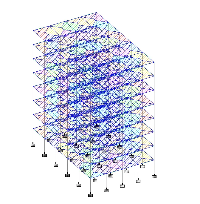
Step 5)
i)WL + X direction
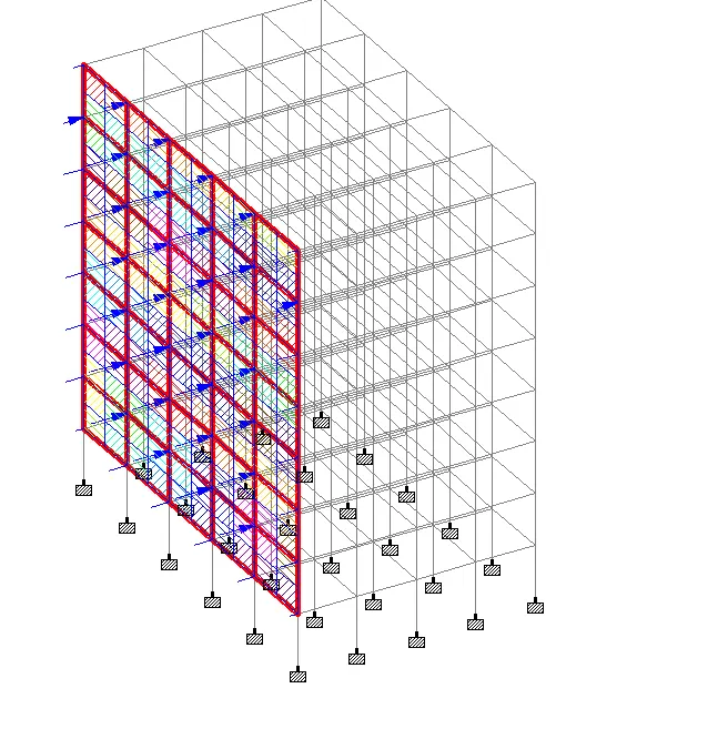
ii) WL -X direction
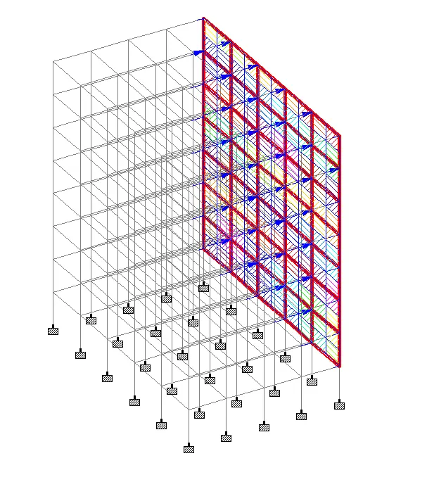
iii) WL +Z direction -
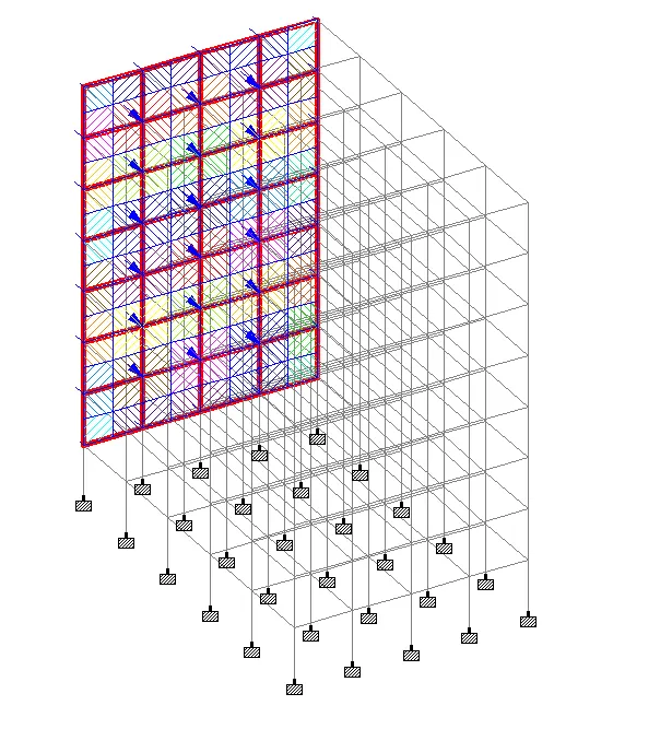
iv) WL -Z direction
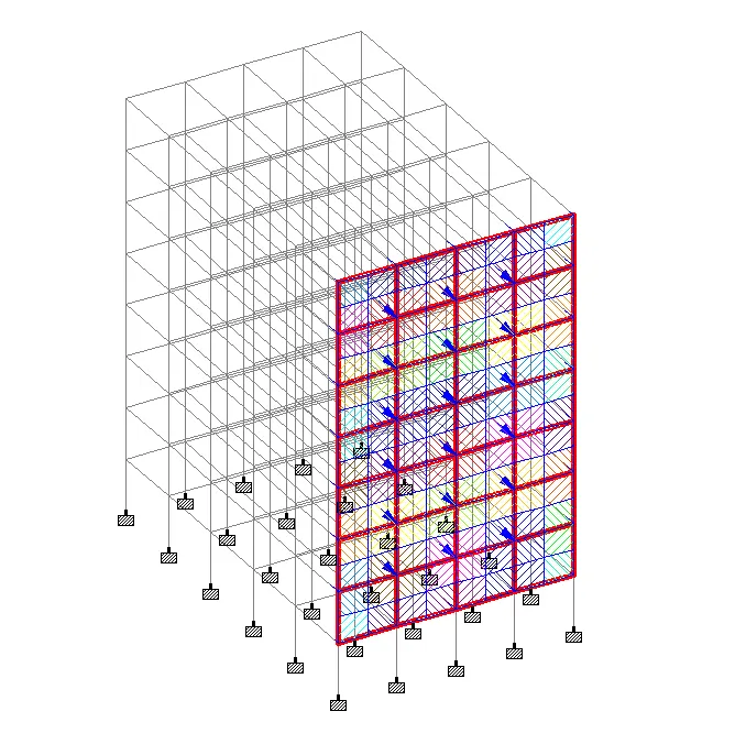
v) DL and LL
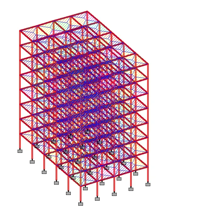
Step 6) Design of slab element
Step 1 ) Data
|
Span Shorter Direction (Clear)
|
ly | = | 5 | m | |
|
Span Longer Direction (Clear)
|
lx | = | 4 | m | |
|
Live Load on the Slab
|
LL | = | 3 | kN / m2 | |
|
Compressive stength of concrete
|
fck | = | 25 | N / mm2 | |
|
Yield strength of steel
|
fy | = | 415 | N / mm2 | |
|
Unit weight of concrete
|
Ƴc | = | 25 | kN / m3 | |
|
Unit weight of floor finish 100 mm
|
Ƴ | = | 22 | kN / m3 | |
|
Clear concrete cover
|
= | 25 | mm | ||
|
Bearing of slab
|
B | = | 250 | mm |
Step 2)
|
Span to effective depth ratio
|
l/d | = | 32 | |||
|
Minimum effective depth
|
d | = | 125 | mm | ||
|
Overall depth
|
D | = | 156 | mm | ||
|
Provide Overall depth
|
D | = | 160 | mm | ||
|
Dia of bars for short direction
|
Φ | = | 12 | mm | ||
|
Dia of bars for long direction
|
Φ | = | 12 | mm | ||
|
Effective Depth
|
d | = | 120 | mm |
Step 3) Loading
i) Dead Load of the slab (DL) = 3.75 Kn/m2
ii) Super Dead Load = 5 Kn/m2
iii) Live load (LL) = 3Kn/m
Total Load on the slab (TL) = 5+3.75+3
= 11.75 Kn/m
Factored Load = 1.5 x 11.75
= 18 Kn/m
ii) Effective span = ly + d = 5000 + 120 = 5.120 m
= lx + d = 4000 + 120 = 4.120
take the minimum value
Therefor ,
Effective length ( Leff) = 4.120 m
iii) Ly / Lx
= 5.120 / 4.120
= 1.2 < 2 ....................................Two way Slab
iv) BM Coefficient as per IS 456
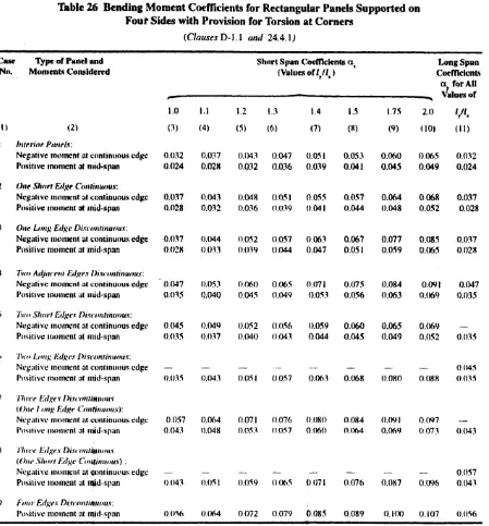
Considered Two adjacent Edges Discontinues (Ly /Lx = 1.2 )
a) For Shorter Span
`alpha _x` = 0.060
`alpha _y`= 0.045
b) For Longer Span
`alpha _x` = 0.047
`alpha _y` = 0.035
Step 4) Bending Moment
Mx = `alpha _x` X w X lx^2
= 0.060 x 18 x 4.120 x 4.120
= 18.33 Kn-m /m ( Negative Moment )
My = `alpha _y` X w X lx^2
= 0.045 x 18 x 4.120 x 4.120
= 13.75 Kn-m /m ( Positive moment )
Mx = `alpha _x` x w x lx^2
= 0.047 x 18 x 4.120 x 4.120
= 14.36 Kn- m /m
My = `alpha _y` x w x lx^2
= 0.035 x 18 x 4.120 x 4.120
= 10.69 Kn- m /m
Considered Max valus of Mx and My
ii) Shear Force - Vu = Wl / 2
= 18 x 4.120 / 2
= 37.08 Kn
Step 5) To check the Effective depth
Mu,lim = 0.138 fck bd^2
18.3 x 10^6 = 0.138 x 25 x 1000 x d^2
d = 72.83mm
d prov > d req ...................................Ok
Step 6) Depth of slab for shear force
i) τc,max = 3.1 N/mm^2
ii) Tv = Vu / bd
= 37.08 x 10^3 / (1000 x 120 )
= 0.30
iii) For τc
Assume Pt % = 0.25
τc = 0.36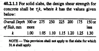
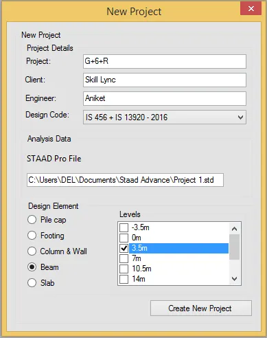
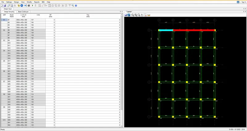
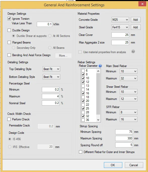
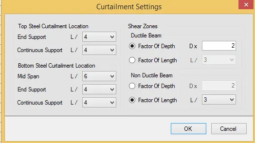
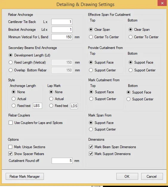
Step 6)
i) Once setting is done
ii) Click on Design and Click on Auto Design
iii) All the load cases which we have defined will come
iv) Select the type of load
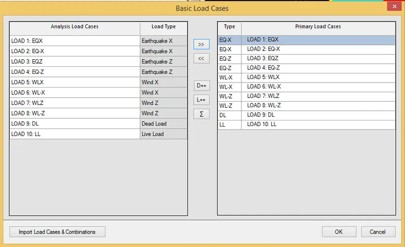
v) Click on Okay
vi) Click on Add from Ananlysis option for adding Load combinations
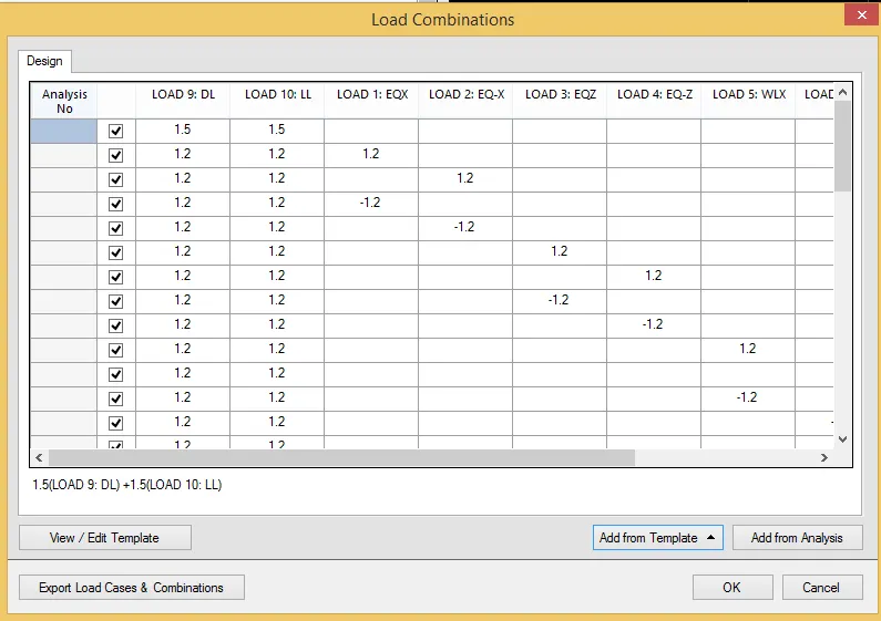
vii) Click on Okay
Step 7)
i) Once you click Okay
ii) Software will design the beams
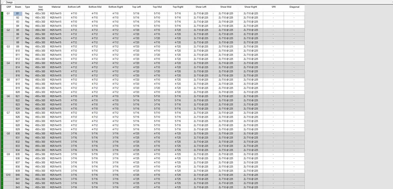
iii) As we can see all the beams are in Green colour
iv) So all the beams are passed
v) And We can see the design also
Step 8) - Preparing BBS
i) For BBS
ii) Click on BBS
iii) Click on Generate BBS
iv) We can select All beams or we can select group wise
v) Select B1-B2-B3-B4
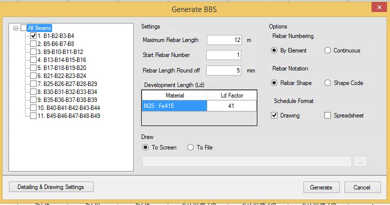
vi)Click on Generate
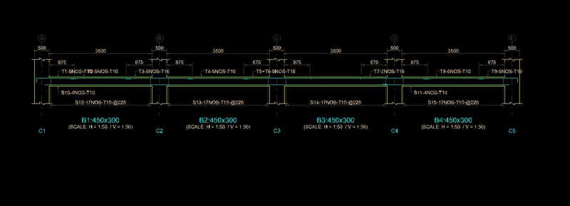
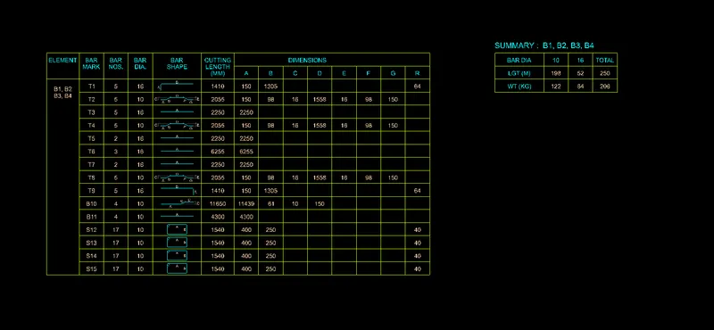
BBS is prepared for B1-B2-B3-B4
Step 9)
i) Click on Report
ii) Click on Design Summary
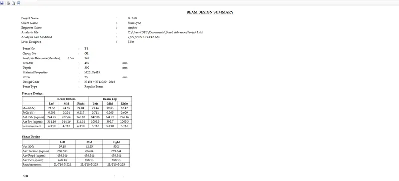
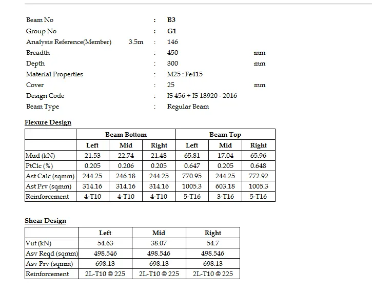
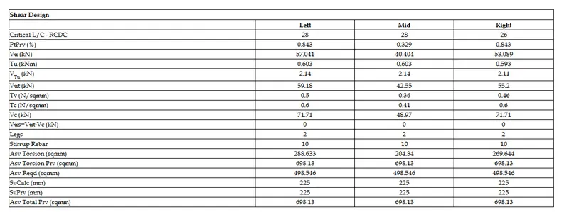
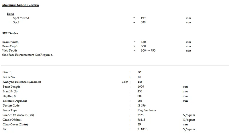
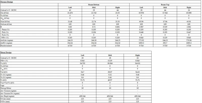
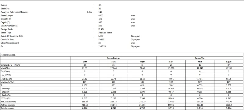
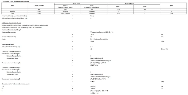
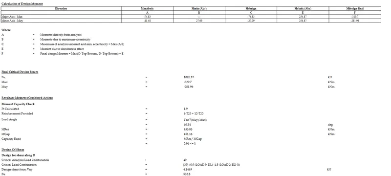
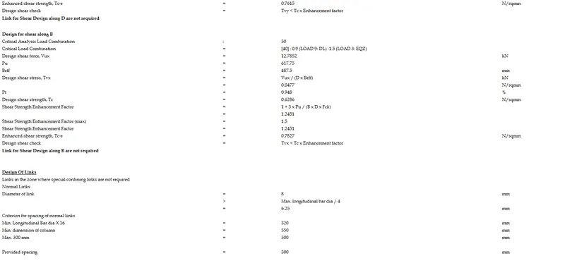
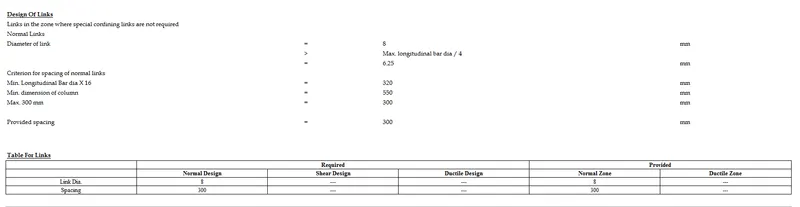
Step 10) Beam Design Calculation Report
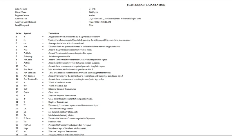
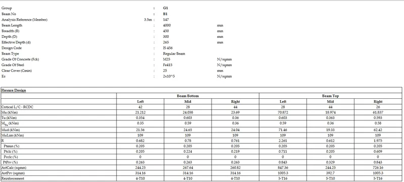
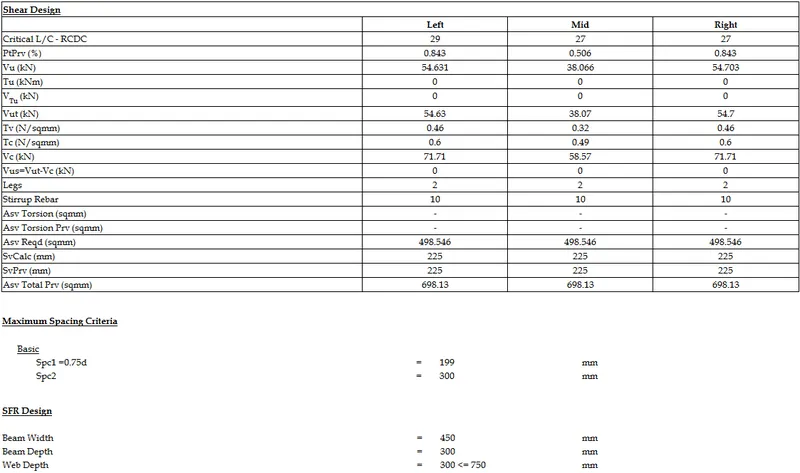
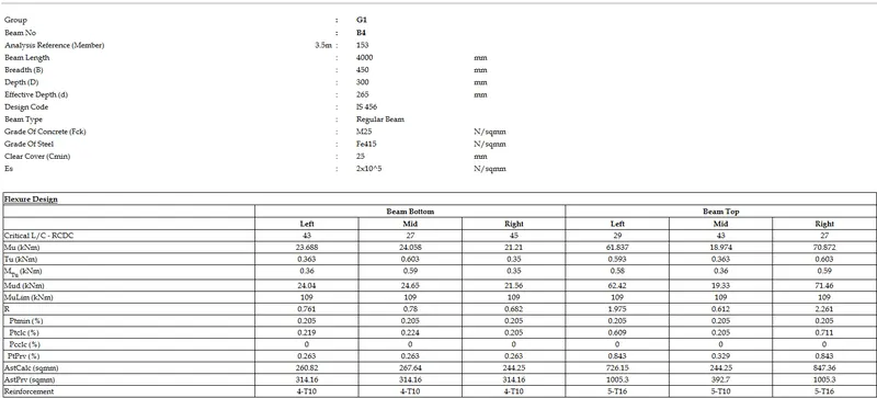
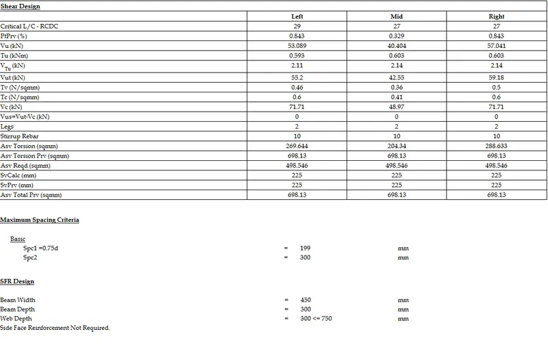
Similarly Follow the same procedure for Column Also
i) Create a New Project
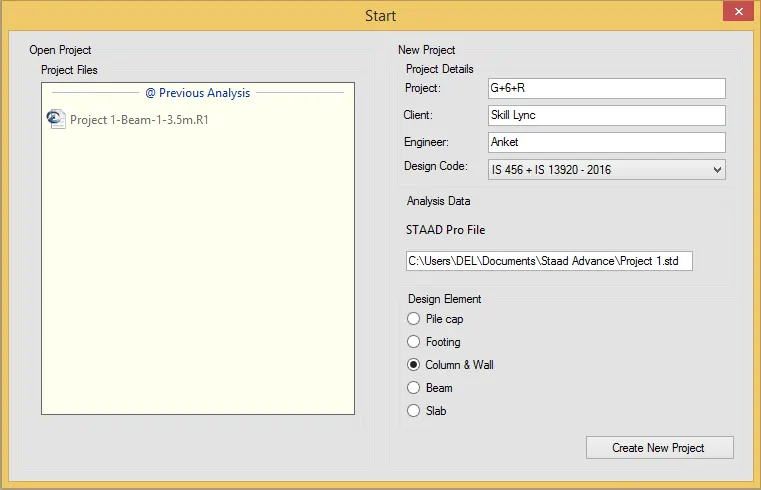
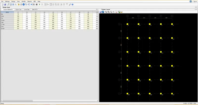
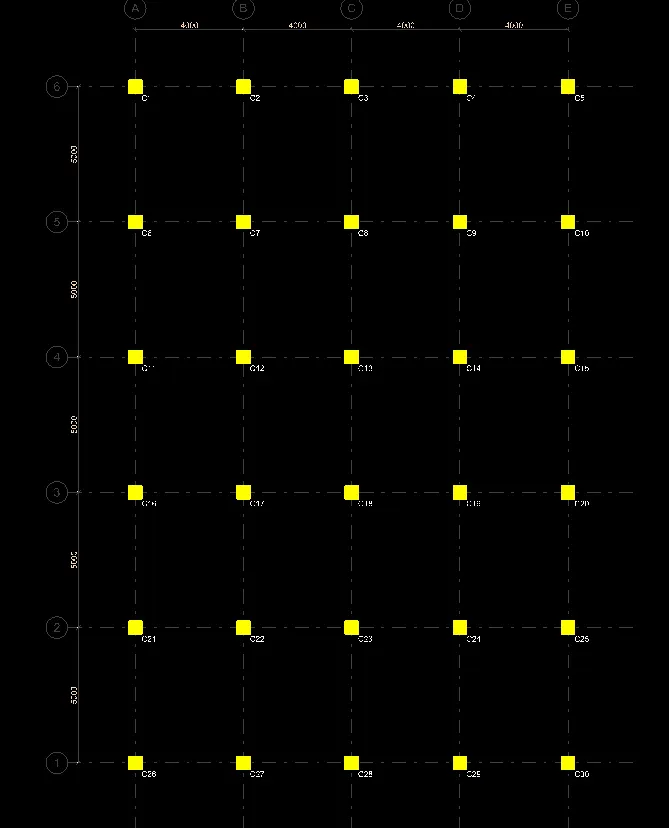
As we can see grids are automatically created with column mark
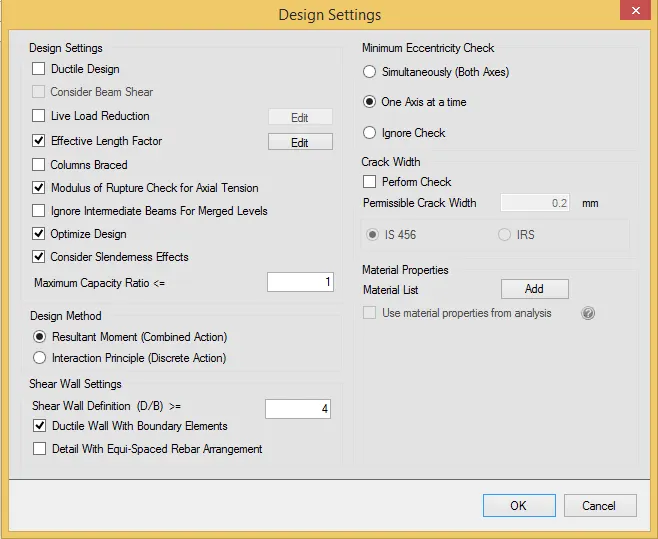
ii) Setting - Design Setting
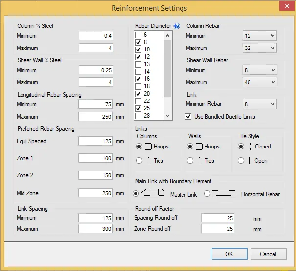
iii) Setting - Reinforcement Setting
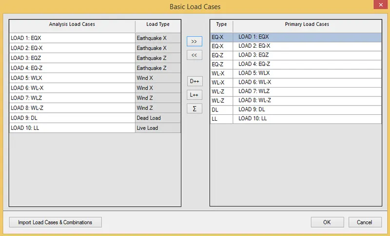
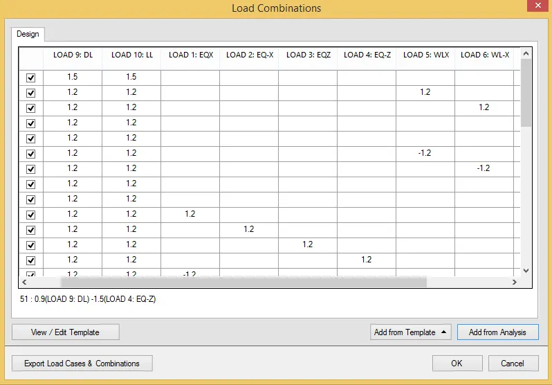
iv) Design - Auto Design
Select load cases and Load Combinations
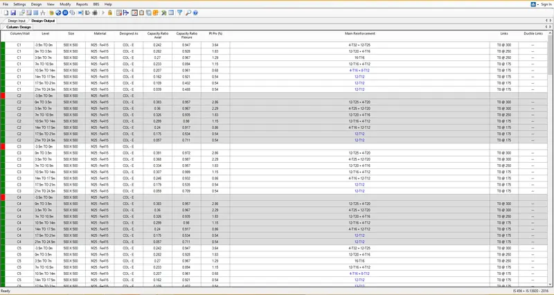
v) Design output
As we can see that Columns are failing
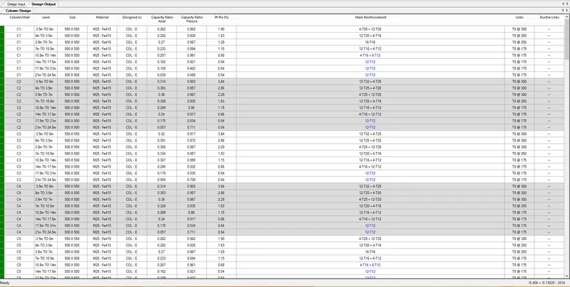
So we need to increase the Column Size
So we need to increase the Column Size
vi) BBS
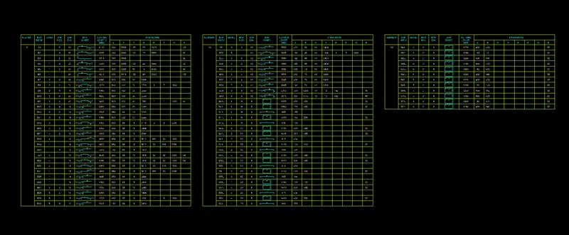
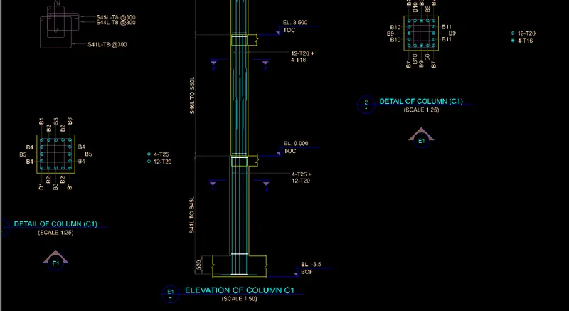
vii) Design Calculation Report for C1
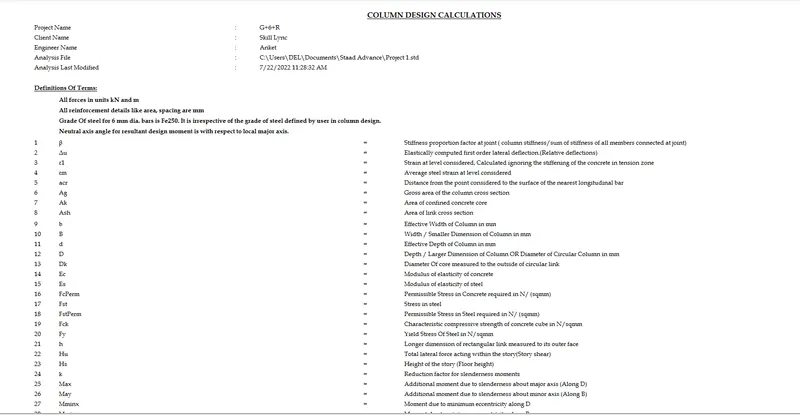
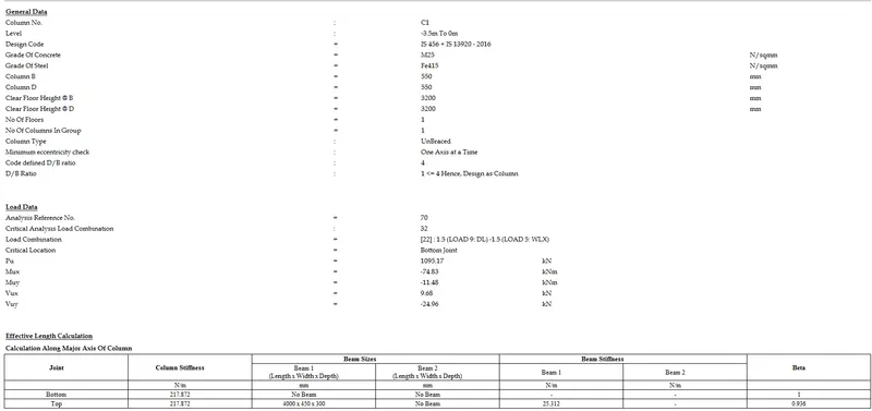
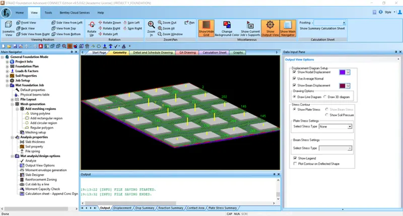
Design Foundations using STAAD Foundation.
Step 1)
i) Open the model
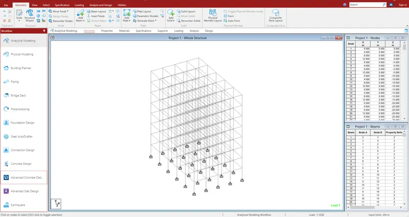
ii) Click on Staad Foundation
iii) Create a Job
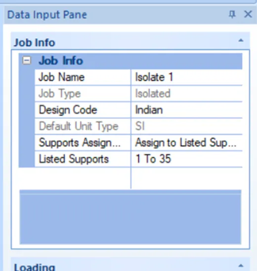
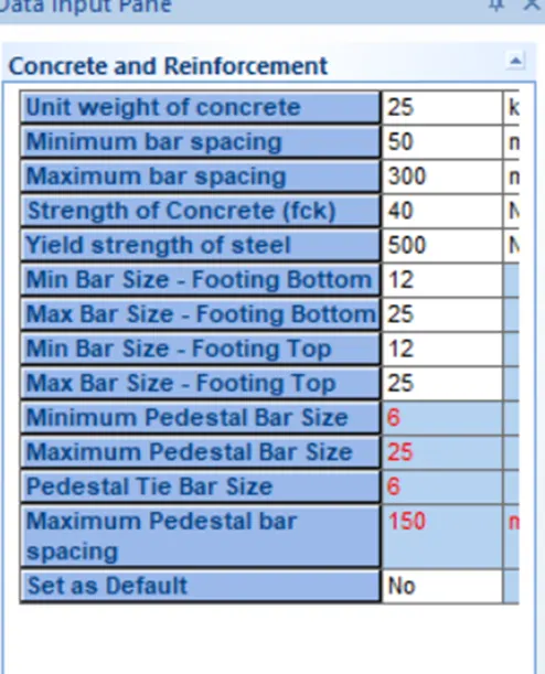
iv) Enter concrete and reinforcement details
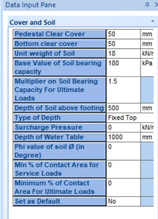
v) Enter Soil property
vi) Click on Design
vii) Once design is completed you will see the details of footing
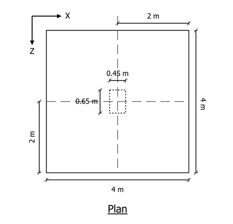
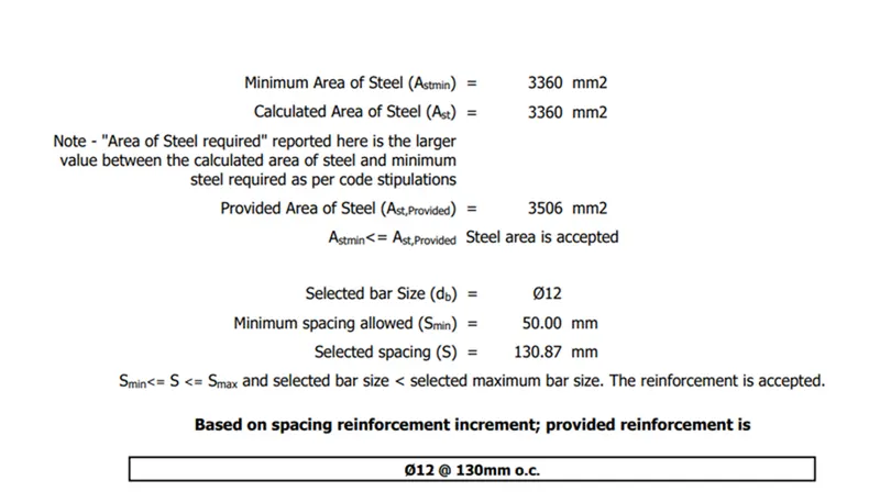
viii) Design output of footing
Results -
i) DBR is prepared from Step 1 to Step 4 ( Input Details )
ii) Structural Model has been created and Analyze it successfully
iii) DL, LL, WL and EQL load are calculated in above steps as per IS 875 standards
iv) Slab element is designed and calculated in above steps
v) Beam and Column is designed in RCDC and Calculation sheet is ptovided in above steps
vi) BBS is also prepared
vii) Foundation is designed in Staad Foundation .