Project 1
Project 1
Objective:
To design the simulink models for three topologies from the given list of converters.
Topologies:
From the list of converters here i had modeled three topologies namely,
1) Buck converter in Continuous Conduction Mode.
2) Buck converter in Discontinuous Conduction Mode.
3) Boost converter in Continuous Conduction Mode.
Buck converter in CCM:
Design of the model,
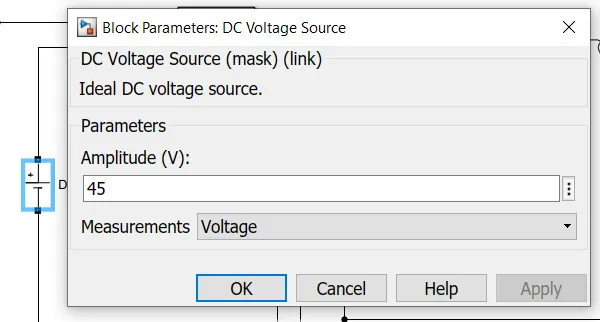
Let the given Input voltage = 45 V.
We need to buck the voltage to 30 V as output voltage as per the topology given.
Power= 500 W
Duty cycle for buck converter in CCM = Vout/Vin
D=30/45 = 0.66.
Let the switching frequency fs= 100KHz
Current through the inductor=Iout = Pout/Vout = 500/30 =16.667 A.
Since the average current flow through the capacitor is 0 Amps , the current should pass through the load resistance is 16.667 A.
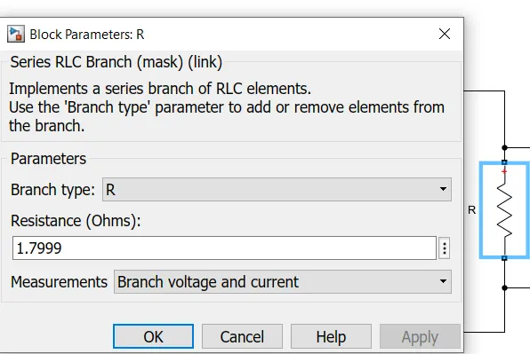
Load resistance R= Vout/Iout =30/16.667 =1.7999 Ohms.
For CCM mode of operation,
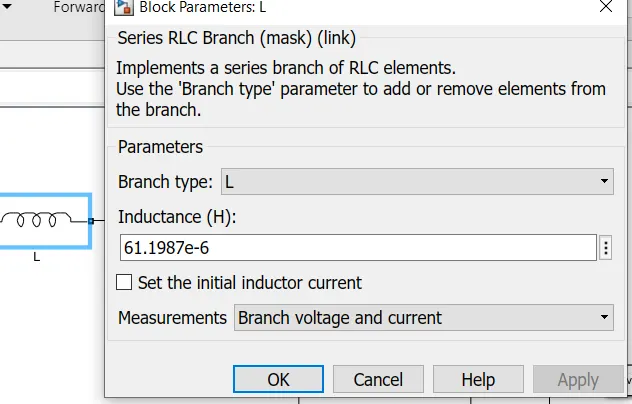
Inductance L = [Vout*(1-D)] / fs* Del.Il
Where, DelIl=Ripple in inductor current(Which should be less than 25%,so taking 10% of Iout)=0.1*16.667=16667 A
L= [30*0.34]/[(100*10^3)*1.6667]
=61.198uH
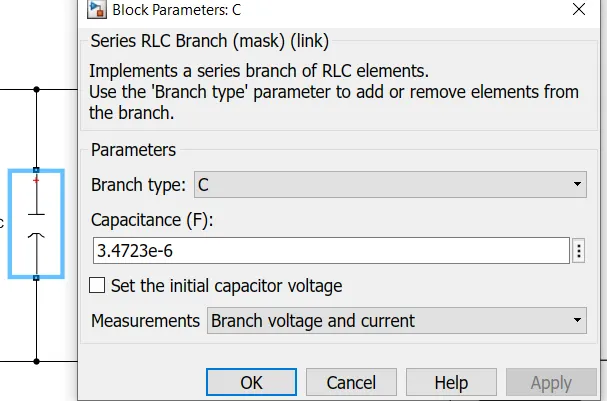
Capacitance C=[1-D]/[8*L*fs*2*(Del.Vout/Vout)]
Where Del.Vout/Vout = Output ripple voltage = 1% (Assumption)
C=0.34/[8*61.198*10^-6*(100*10^3)^2*2*0.01]
=3.4723uF
Model:
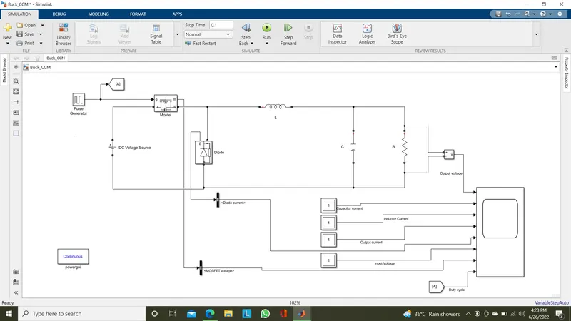
Explanation:
The Continuous Conduction Mode of operation refers as the inductor current flow will be in a way which will not comes to zero amps during the ON stage of duty ratio.
Here which refers on the ON period of the switching the inductor current will not touch the zero value through out its operation.
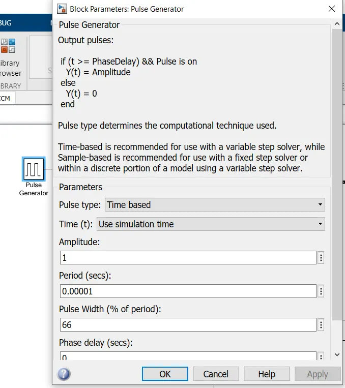
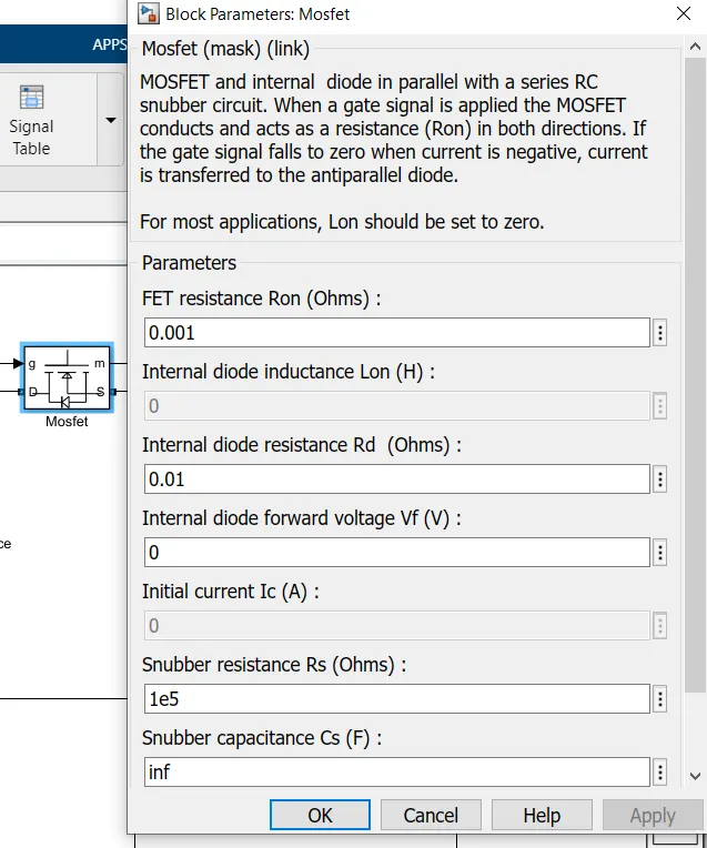
The input voltage given as a voltage source which was bucked using the MOSFET switch periodically corresponding to duty ratio.Pulse generator is used to produce the pulses for the MOSFET.
Here a diode is used in parallel to the input voltage source to make the circuit closed during the OFF period of the MOSFET switch.
We know the average current flow through the capacitor is always zero,the current during the ON and OFF periods will flow entirely through the load resistance R.
These operations makes the circuit to continuously flow the current to complete the circuit and operate in Continuous Conduction Mode(CCM).
Specifications:
Pulse generator,
Input Voltage Source,
Mosfet,
Inductor,
Capacitor,
Resistor,
Results:
Zoom out view,
Zoom In View,
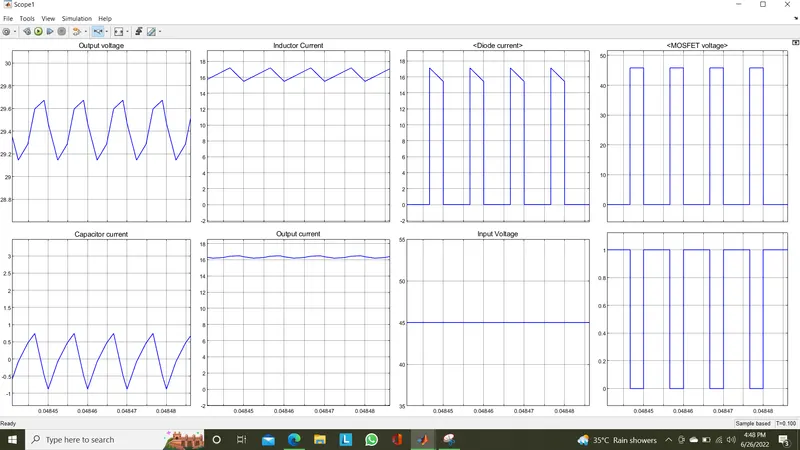
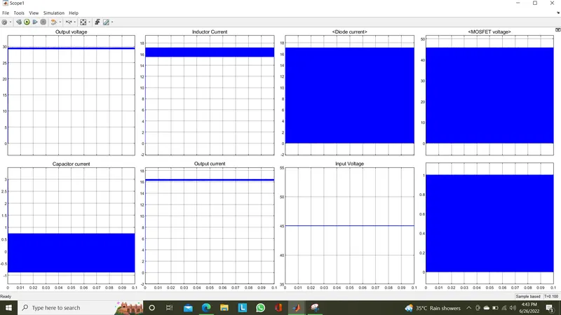
We are the output voltage as approximately 29.5 V , the average current passing through capacitor is 0 Amps.The current passing through the inductor is approximately 16.6 Amps as we designed for 16.66Amps also operates in CCM of operation.
Buck Converter in DCM:
Design of the model,
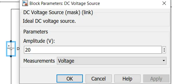
Let the given Input voltage = 20 V.
We need to buck the voltage to 5 V as output voltage as per the topology given.
Power= 100 W
Duty cycle for buck converter = Vout/Vin
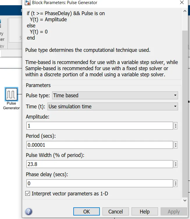
D=5/20 = 0.25.
Let the switching frequency fs= 100KHz
Current through the inductor=Iout = Pout/Vout = 100/5 =20 A.
Since the average current flow through the capacitor is 0 Amps , the current should pass through the load resistance is 20 A.
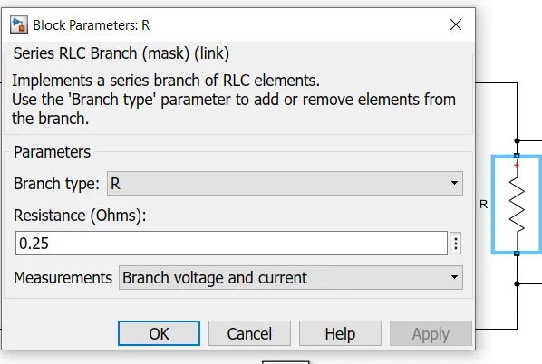
Load resistance R= Vout/Iout =5/20 =0.25 Ohms.
For continuous current the inductance of inductor is,
Inductance L > [(1-D)*R] / [2*fs]
L> [0.75*0.25]/[2*(100*10^3)]
L > 0.9375 uH
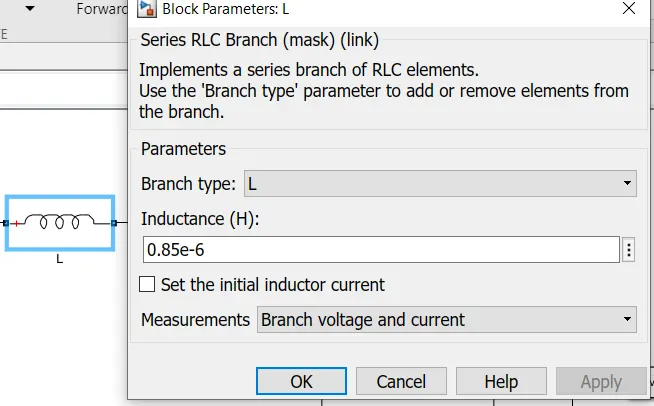
So,for DCM mode of operation let as consider the inductance value as L=0.85uH
So we need to find the new duty ratio for DCM of operation,
Vout/Vin = D/(D+D1)
Where D1 is the actual OFF period time of switch for DCM mode which should be as D1 < (1-D)
Vout/Vin = 2D/(D + sqrt(D^2 + (( 8*0.85*10^-6)/(0.25*1/10^5)))
0.25=2D/(D + sqrt(D^2 + 2.72))
sqrt(D^2 + 2.72)= 7D
D^2=2.72/48
D=0.238
Therefore,
Vout/Vin= D/(D+D1)
5/20=0.238/(0.238+D1)
D1=0.714
Therefore D1< (1-D) makes Discontinuous mode of operation is satisfied.
Capacitance C=[1-D]/[8*L*fs*2*(Del.Vout/Vout)]
Where Del.Vout/Vout = Output ripple voltage = 1% (Assumption)
C=0.762/[8*0.85*10^-6*(100*10^3)^2*2*0.01]
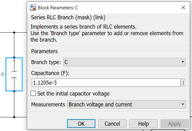
C =1.1205mF
Model:
Explanation:
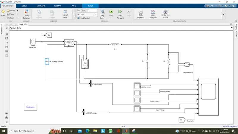
Here for the operation of buck converter in Discontinuous Mode of operation ,the model is same but specifications of inductor, capacitor and duty ratios were different as we designed above.
The DCM mode of operation will make reduce the inductor size when compared with CCM mode of operations which ultimately reduce the cost of the system.
The difference between the CCM and DCM of operation is the difference in operation during the OFF time of switching.
The Energy stored in the inductor is discharged through load and diode but this stored energy is not enough to supply the load for the whole duration of OFF time period.Hence there is no current through the inductor for some duration of time. This mode refers as Discontinuous mode of operation.
Specifications:
DC Voltage Source,
Pulse generator,
Inductor,
Capacitor,
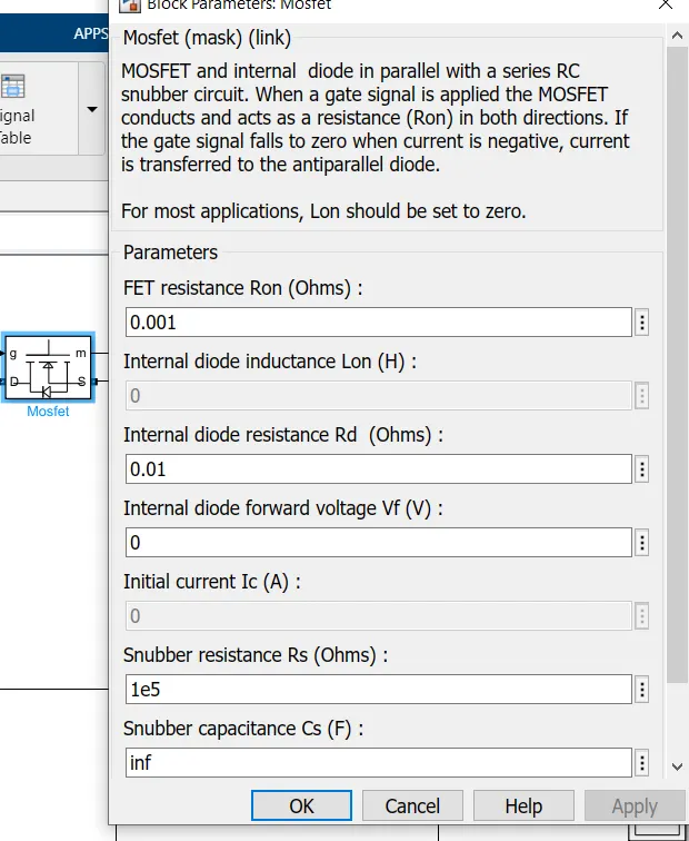
Mosfet,
Resistor,
Results:
Zoom out view
Zoom In view
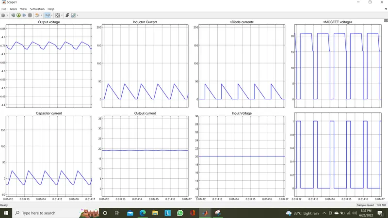
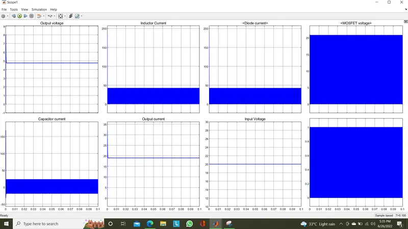
We can see that the output voltage is arround 4.75 V and the inductor current is not continuous during the OFF period of the switching. It reaches 0Amps for a few seconds at the end of OFF cycle then it again rises during ON cycle.
This shows clearly the DCM of operation of buck converter.
Boost Converter in CCM:
Design of the model,
Let the given Input voltage = 20 V.
We need to boost the voltage to 40 V as output voltage as per the topology given.
Power= 600 W
Duty cycle for boost converter in CCM = Vout/Vin=1/(1-D)
1/(1-D)=40/20
D=0.5
Let the switching frequency fs= 100KHz
Current through the resistor=Iout = Pout/Vout = 600/40 =15 A.
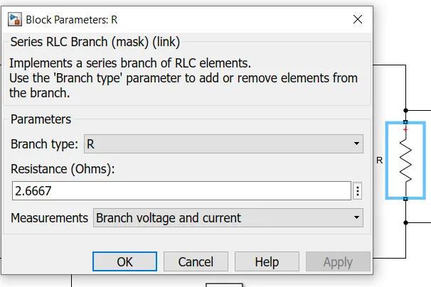
Load resistance R= Vout/Iout =40/15 =2.6667 Ohms.
Inductor Current, Il=Iout/(1-D)= 15/0.5=30Amps
For CCM mode of operation,
Inductance L = [Vin*(D)] / fs* Del.Ill
Where, DelIl=Ripple in inductor current(Which should be less than 25%,so taking 10% of Iout)=0.1*30=3 A
L= [20*0.5]/[(100*10^3)*3]
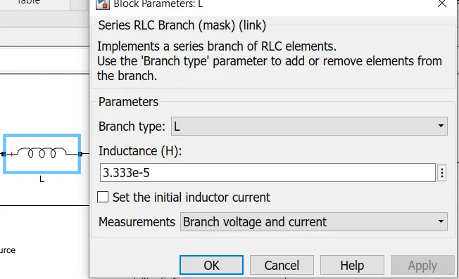
=3.333e-5H
Capacitance C=[D]/[R*fs*(Del.Vout/Vout)]
Where Del.Vout/Vout = Output ripple voltage = 1% (Assumption)
C=0.5/[2.6667*(100*10^3)*0.01]
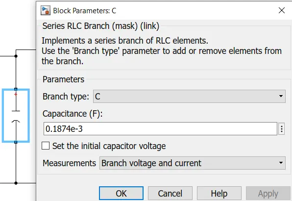
=0.1874mF
Model:
Explanation:
The Continuous Conduction Mode of operation refers as the inductor current flow will be in a way which will not comes to zero amps during the ON stage of duty ratio.
Here which refers on the ON period of the switching the inductor current will not touch the zero value through out its operation.
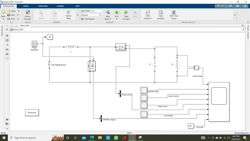
The input voltage given as a voltage source which was boosted using the MOSFET switch periodically corresponding to duty ratio. Pulse generator is used to produce the pulses for the MOSFET.
Here MOSFET is used in parallel to the input voltage source to make the switching and the diode moved to output side.The Inductor moved to input side as shown in model.
During ON period the inductor is charged and during the OFF period the current flow through diode,capacitor and to the resistance load makes the boost operation.
During OFF period the load gets energized by the capacitor connected in output side parallel to load. Since the capacitance(like secondary source) is higher for boost converters when compared to buck converters.
These operations makes the circuit to continuously flow the current to complete the circuit and operate in Continuous Conduction Mode(CCM).
Specifications:
DC Voltage source,
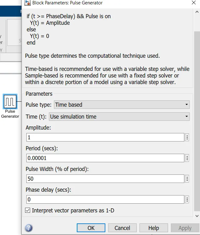
Pulse generator,
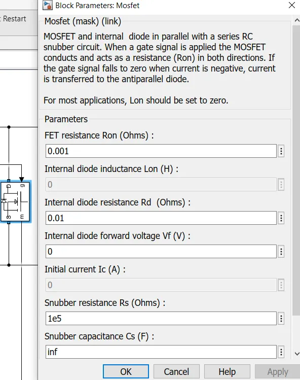
Mosfet,
Inductor,
Capacitor,
Resistor,
Results:
Zoom out view,
Zoom in view,
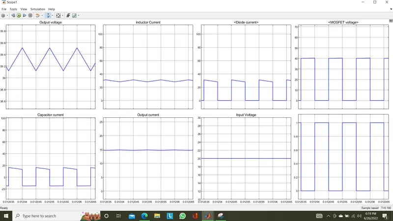
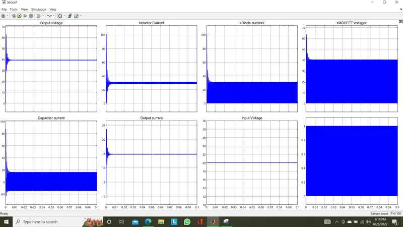
We can see that the output voltage is boosted to arround 39.4 V form input 20V, also from the inductor current plot it confirmed as CCM of operation as it doesn't touches 0 Amps during the OFF period of duty cycle.
Conclusion:
Thus using this project we designes and simultated the models of buck converter in DCM,CCM modes and boost converter in CCM mode.
The results were concluded as per the mode of operations in taken three topologies.
Thank you
Submitted by,
Praveen Kumar L V