Project 1
AIM:
To Route the Wiring Harness on Given Engne and Prepare the flattenview drawing in CATIA V5. Application of all Packing rules, Industry best practices studied in this course shall be demonstrated in design.
To Route the Wiring Harness through the engine for the ignition (Spark plug) using install the connectors to the desire position and then routing before route to define the connectors and clips and clamps and support equipment as Electrical component.
OBJECTIVE:
The objective of the project is to route the wiring harness on given Bugatti V16 Engine and Engine and prepare flatten view drawing in CATIA V5. All types of packaging rules have to be considered while routing the harness. Also, Industry best practices should be demonstrated in design. All the necessary details like clearance, Cliping/clamping selection, harness fixing requirement, harness continuity should be provided in order to design wiring harness.
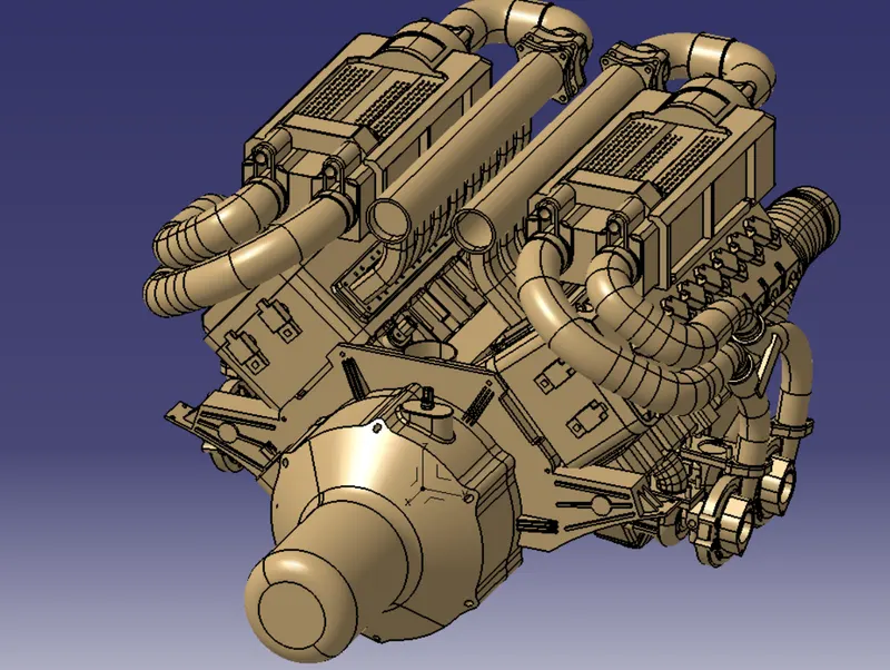
To download the required model of Engine ( Bugatti V16 Engine where the 16 valve 8 cyclindera are placed on the right side and 8 cyclinders are placed on the left side.
There are totally 16 injectors where 8 injectors are used for cylinders on right side and 8 injectors are used for another 8 cylinders on left side.
Also there are 4 camshaft sensors, so there are totally 20 sensors that we have to connected electrically.
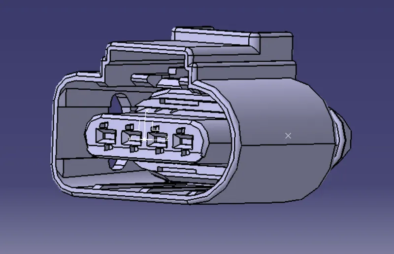
Generally, 4 pole connectors are used for fuel injectors of the engine.
The engine will also have an interconnection connectors which will connect the engine to other parts of vehicle. We will be Using a 12 pole electrical connector with a mounting clip features us an interconnection connector.
The plastic guiding channel used in this harness should be made of material that can withstand at least 150 degree Celsius.
The bend ratio for the all the bundle segment should be 1.4 .
KNOW ABOUT REQUIREMENT:
Provides clips/clamps as per requirement.
Make sure there is no any fauling case will designing the wire harnessing additional clips clamps may be used to avoid fauling case.
Give additional slack if needed 5 to 10% slack is sufficient.
Avoid routing over bolt and bolted joints to avoid harness punctures.
Avoid routing on sharp edges or else provide protection over the harness.
Follow the clearance distance and keep away the harness from heat generating component if it is very important to cover the cuttubes according to norms.
Protection should be providers needed according to surrounding temperature with temperatures vary the cottube materials also varied avoiding direct support for harness on fuel line routed in engine.
Use the routing channel it's to use protect the wiring harness and route 2 deserve location. And it may possible get the branches in the guiding channel.
Branch length should be greater than 50mm. Minimum distance between 2 branch points should be at least 50 mm. Minimum distance between clip and branch points should be at least 25mm.
Make sure that to require wiring diameter for the main branches and different to sub branches to connect the connectors and the Ben radius should be important.
The given Bugatti re 16 engine has 16 fuel injector sensors and 4 Cam shaft sensor. In totally we have 20 sensor that have to be connected electrically.
The engine will also have a interconnection connector which will correct the engine to other parts We will be using the 12 pole electrical connector with mounting clip future as an interconnection connector.
The plastic guiding channel used in this Harness should be made up of material that can stand at least 15 degrees Celsius.
INTRODUCTION:
A wiring harness is an organized set of wires, terminals and connectors that run throughout the entire vehicle and transmit information and electric power, thereby playing a critical role in “connecting” a variety of components.
GEOMETRY PARAMETERS AND ELECTIRCAL CONNECTOR :
Firstly loaded CAD model make the piont on mating and bundle entry side. Andthen make the axis (Co-ordinate) system of the Connector connection point all in the Mechanicl Design in Part Design.
One things we want understand is Axis system was poistion or orientation of axis
1) X-Axis is orintation of locking mechanism.
2) y-Axis is normal to the another connector.
Define the Electrical connector in Electrical part design system. After declear electrical connector model turns to electric part identify by the wating tree structure. And pop up the dialog box.
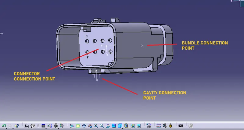
Define Bundle Connection point which is terminate wire should be inserted on this side(This point defines where the harness bundle segment point will end when routed to the electrical connector) even there is popup the dialoge box for creating Bundel connection point gives the asked perspectives.
Define Connector Connection point is mating side of connector (This point defines is used for the connection of one connector to another connector) even there is popup the dialoge box for creating Connector connection point gives the asked perspectives.
"CONNECTOR C-1563689-1"
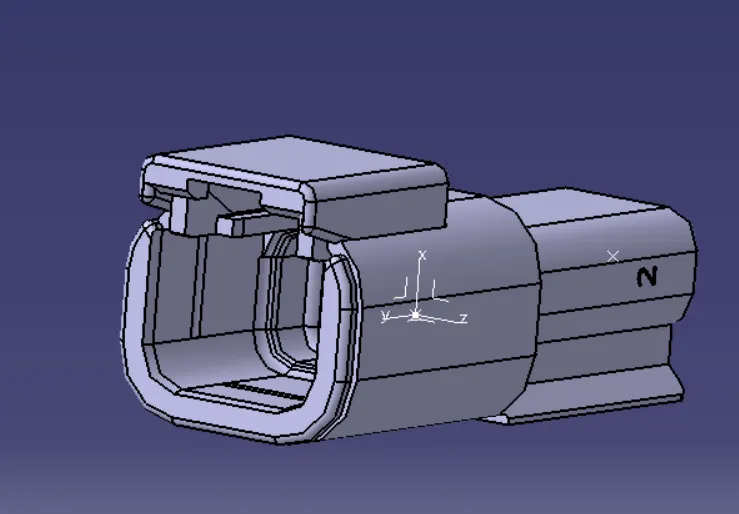
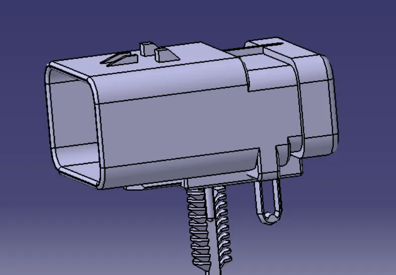
"CONNECTOR C-776438-4"
CONNECTOR MOUNTING:
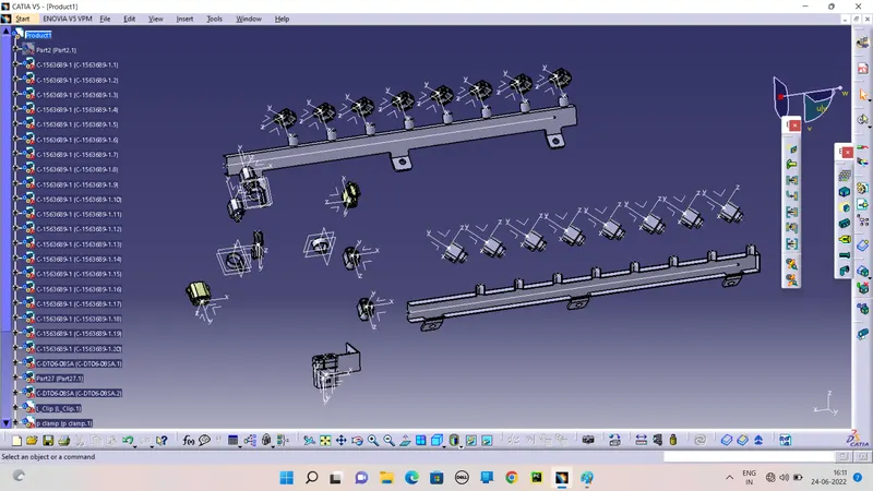
The connectors are mounted in the appropriate position of where the elctrical engergy and signals are requires and locates the fuel injector sensors and cam shaft sensors.
After define it is electrically put in to the engine model by the help of compoes and manipulator method.
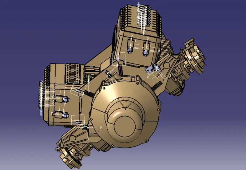
Sure that the connector connection point and bundle connection points are in correct direction and position also to view of skeliten some of the connector is mounted in the clambs to the uncomfortable fitting places.
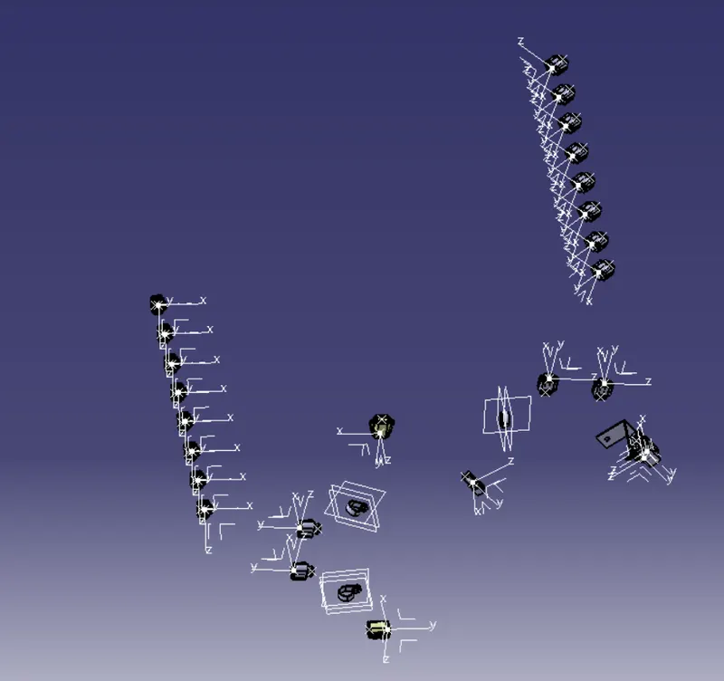
CLIPS AD CLAMPS:
Cable clamps are mechanical devices or clips that define a route for one or more cables along a building wall or within an instrumentation, control or other type of electrical enclosure. They provide all the mechanical support required.
Wire rope clips are a common and necessary piece of rigging hardware when it comes to using wire rope and forming end terminations. They are used to form a wire rope eye or to connect two cables together.
We are use the p-clamps and L-clamps and also define it is electrical component as well as to use the wiring harnedss and connector placed over the L-clamp in the required position and the connector not directly placed over it by the help of another cavity connector.
Define the P-clamps in the electrical we must needed the points and planes of the clamps. So we must to declear the points and planes of geometry parameters.
After define it support by the represent the points and planes by the support tools.
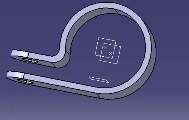
The p-clamps are used for wire routing through the clamps are to fix the wire without slag and slack.
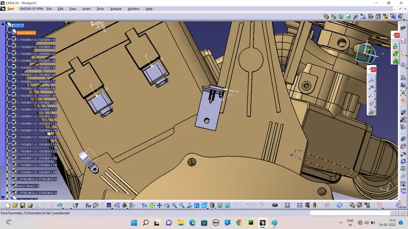
L CLAMP WITH CONNECTOR MOUNTING:
L-Clamp is used to mount the connector over this the clamp to the engine this is support part.
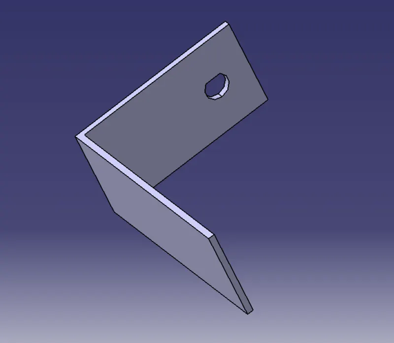
The L-clamp is support together with the engine.
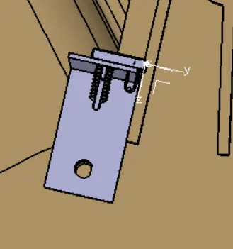
Defining the Interconnection connector and mounting clip electrically and then mounting it on the created bracket. Mounting.
A 12-pole "C-776438-4" connector and mounting cavity "C-1924487" is used as an interconnection connector. The 3D-CAD data file for the required connector and the cavity is dowloaded from TE.com. Both the connector and the cavity are electrically defined and mounted on the sheet-metal bracket.
GUIDING CHANNEL:
The Bugatti V16 engine has 8 fuel injector on the left side and 8 fuel injector on the right side of the engine also this fuel injector sensors are located very close to each other so the best way to route the wire around them it's by using a plastic grating channels as the well help as organise all the why are very seriously and will reduce complex wiring harness routing to mount a plastic guiding channel we would need some mounting provisions the engine design team can be consult and asked to provide mounting threaded holes or threaded bosses.
There will be 2 different plastic dating channel for the engine one of the left and other one for the right side of the engine. He has to be made show the proper clearance ( at least 5 mm) is provide between the plastic channel and exhaust pipe. They totally thickness of this channel is 25 mm.
The plastic guiding channel will be a 2 pieces molded the plastic that will protect the wiring harness from surrounding temperatures, wear and tear while providing nice aesthetics to the engine.
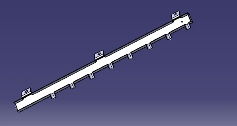
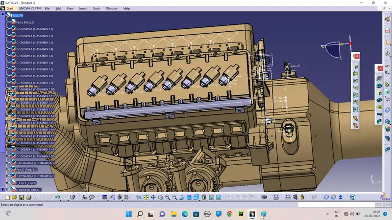
To routing the wire through the guiding channel to product the wire bundle from the high temperature and wear tears.
Routing through the GuidingChannel.
BUNDLE ROUTING:
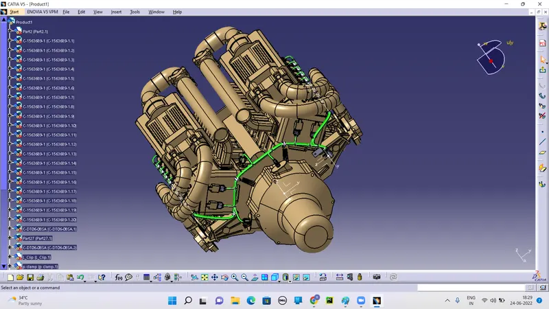
Start the routing in the engine part we go to the Electrical Harness Wiring tool work bench and define the geometry bundle and the start the routing by the tool of Multi branch routing. To declear the diameter and slack of the wires.
| WIRE TYPE NAME | DIAMETER | SLACK | DETAIL |
| Main-Bundle | 15 mm | 0 | Rout the main bundle in the 15mm diameter wires and through to end the sub branches are divided in the main wire. |
| Sub-Branch Bundle | 8 mm(Show the different) | 10 | The sub branchs are dividing in the mau=in bundle with the 10% slacks. |
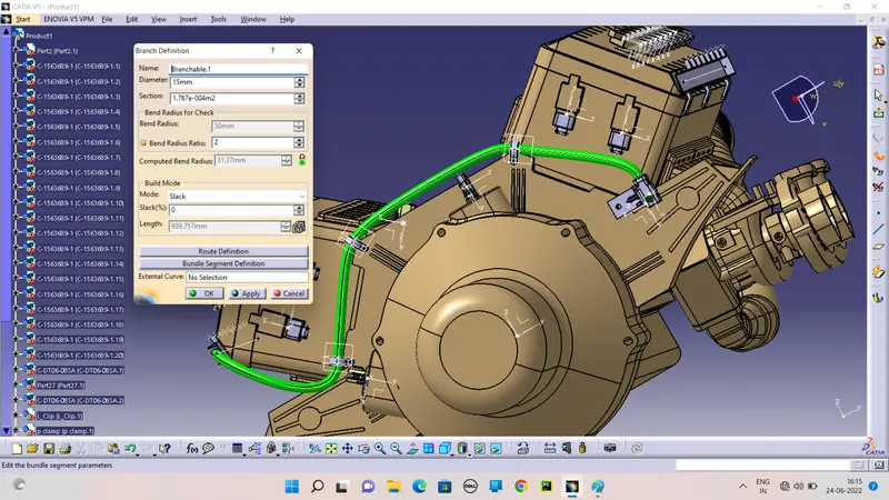
Route the wires through the p-clamps and link with the guiding channels of left and right side of the engine.
The sub branch bundle are divide in the main brancheswith the slack.
Another branch point is added at particular distance from the interconnection connector. From this branch point, the bundle is routed to the rigth side guiding channel. It can be noticed that there is no need of any additional mounting provisions for this bundle segment as the bundle path is practical and completely possible in the real world situation.
Add the branch point the get the sub branch bundle from the main branch. 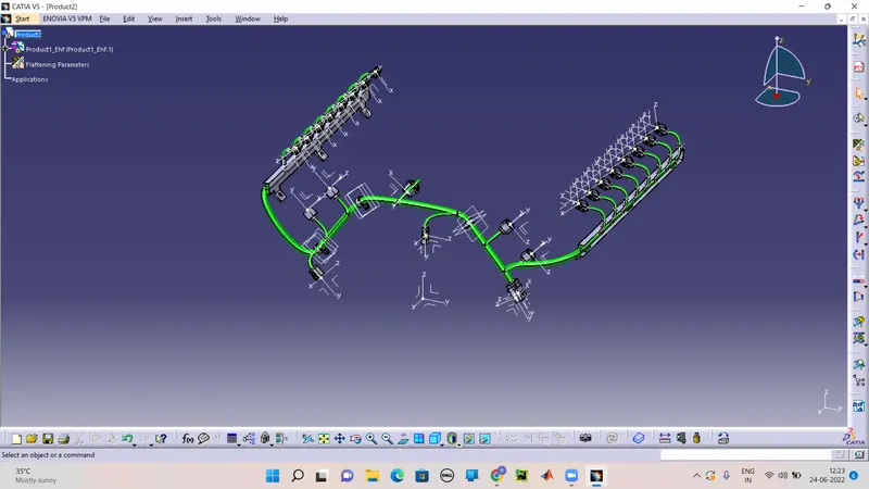
CHECKING BUDLE CONTINUITY:
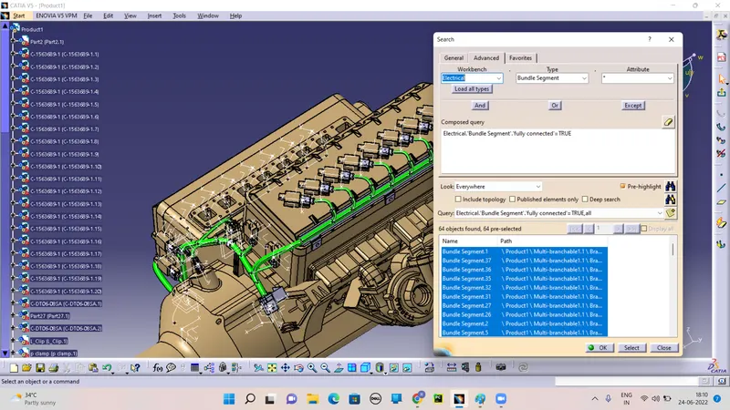
First, we have to make sure that multi-branchable is selected and then we have to go in EDIT>SEARCH>ADVANCED>ELECTRICAL WORKBENCH>TYPE-BUNDLE SEGMENT>ATTRIBUTE-FULLY CONNECTED
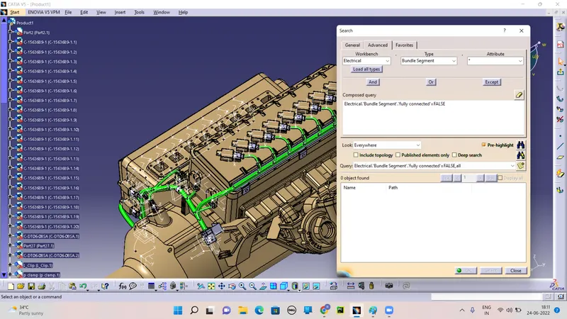
Selecting the "TRUE" option will show all the connected bundle segments while the selecting "FALSE" will show all the non-connected bundle segments.
For now, we will select "TRUE" and search for results. All the bundle segments are highlighted and found showing that all the bundle segments are electrically connected.
And try to we will select "FALSE" and search for results. All the bunble segments are shown empty and found showing that all the bundle segments are electrically connected.
CREATING FLAT-PATTERN OF WIRING HARNESS BUNDLE:
To make a flattened view of any wiring harness we should be working in the Electrical Harness Flattening workbrnch of CATIA V5.
We should also make sure that the flattening file is saved in the same folder where we have all the parts of the harness assembly.
Defining the Harness Flattening parameter. Make sure to use the "Single Line" for the bundle segment and "Double Line" for protective covering.
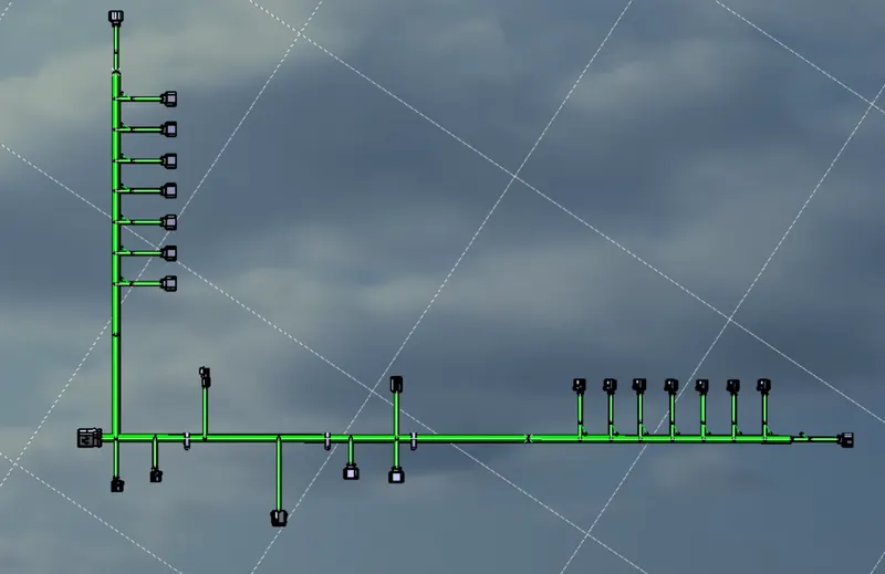
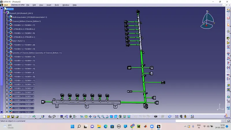
Extract and bring the bundle assembly into the Engine Harness Flattening product file and then flatten the file along the XY plane.
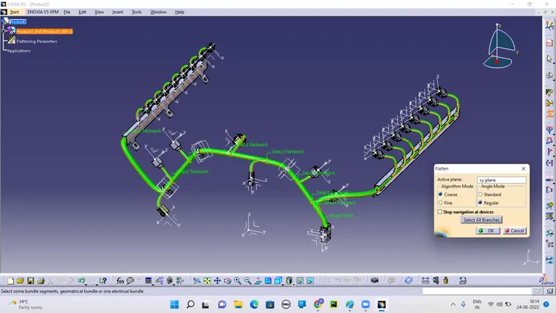
Rotate the bundle segments connecting to the four cam-shaft connectors by uding the "Rotate" feature in the flattening workbench. It should be noted, That we have "XY-plane" as the flattening plane so we should make sure that we rotate the bundle segment only along the "XY-plane".
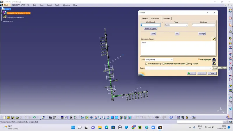
Along with hide the plane axis and points in the product. By the Search tool.
CREATING A FLATTEN-DRAWING VIEW FOR THE WIRING HARNESS ASSEMBLY:
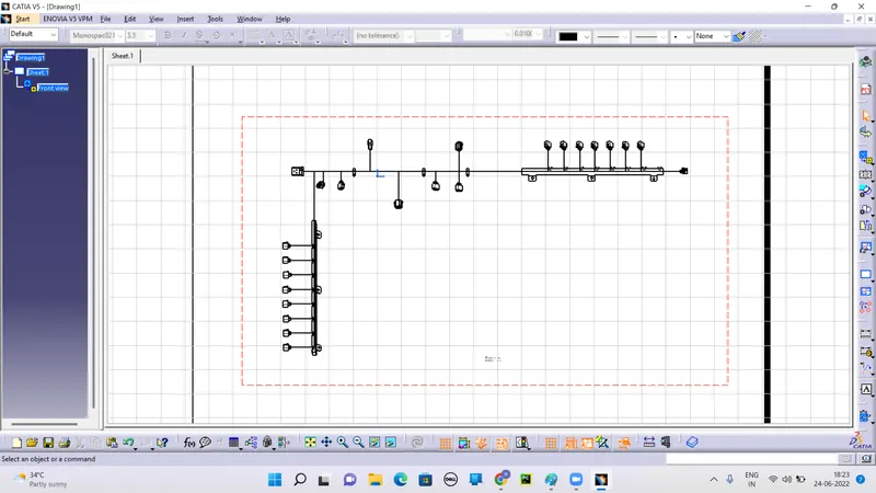
Make a new drawing file and define all the necessary drawing parameters. Insert the front-view of the harness assembly into the drawing file.
Define the drawing properties as shown below. It should be noted that for the "Dress-up" setting 3D wireframe is always "ON". If this setting is not selected then the bundle segment will not be visible on the drawing view.
FINAL PRODUCT:
CONCLUSION:
Routing of the wiring harness for the Bugatti V16 Engine assembly was done and the flatten-view drawing was prepared in CATIA V5. The drawing posted above in for the left and right guiding channels have to be used with the wiring harness flatten-view drawing. Various packiging rules and constraints were considered while routing the harness. Industry best practies were implemented in the harness design. All necessary details like clearance/ clamping selection, harness fixing requirements, harness continuity were provided in order to desing the wiring harness.