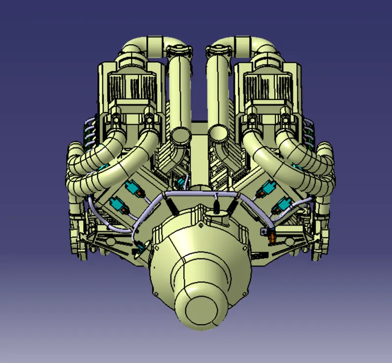
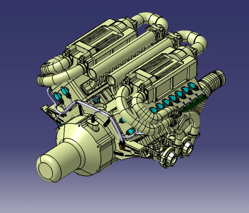
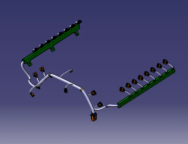
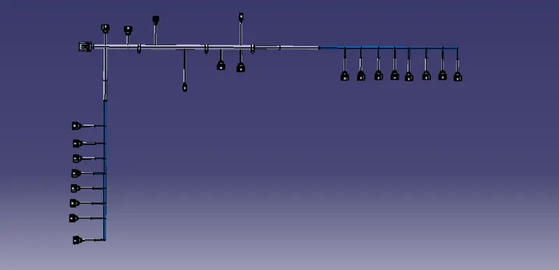
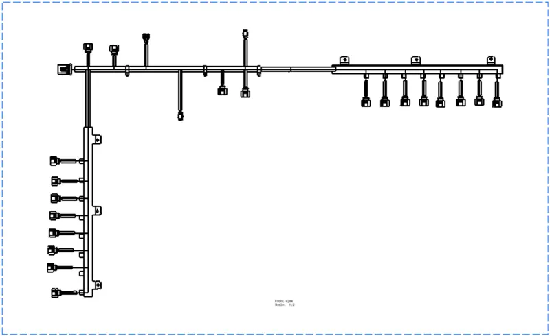
Automotive Wiring Harness Routing for Bugatti V-16 Engine
Aim:
To prepare the wiring harness routing for the given Bugatti V-16 Engine.
Objective:
The main objective of this project is:
- To create the wiring harness routing for the V-16 Engine by using appropriate connectors, clips and clamps which is required.
- To create a flatten view drawing file in Catia v5.
- Need to apply the protection covering like cot tubes and insulation tapes to the bundles as required.
- Need to apply the industry best packaging rules and best practices studies in this course while preparing the wiring harness routing for the V-16 engine.
Packaging rules and assumptions made in this project:
- Avoid harness routing and clipping in a blind zone.
- Avoid harness routing through the small structural holes and openings to minimise the chaffing and handling of the wiring harness during installation.
- Provide additional slack to the harness according to the surrounding and harness bending requirements. And avoid excess slack to the harness.
- Provide sufficient clearance to the different surrounding parts.
- Avoid routing over the bolts, near to the bolted joints or screwed joints. Because it may damage the harness or may puncture the harness.
- Avoid routing near the sharp edges like thin sheet metal brackets, panel joints, etc.
- Provide at least 100mm clearance to the harness from the ABC pedals, clutch lever & cables, Engine timing belt or any other dynamic components.
- Enough clips and clamps should be provided to ensure the positive clearance with the surrounding and safety of the wiring harness.
- Ensure distance between two clamps on a straight branch should be maximum of 200mm.
- Clamping requirements should be decided based on the harness bending, surrounding and mounting arrangements.
- Provide positive clamping at the engine and chassis to avoid the harness damage when Engine rocks.
- Keep harness away from the transmission dynamic assemblies like drive shaft or propeller shaft.
- Provide the guiding channel if it is required.
- Use the rubber gromets which provide the proper sealing, and also protects the harness from the sharp edges and absorbs the vibrations.
- Wiring harness minimum branch length should be 50mm.
- Minimum distance between the clip and nearest branching point should be atleast 25mm.
- Minimum distance between two breakouts should be 50mm.
- Limit the number of branches coming out from the single branch to 4.
- Provide the bracket for the interconnection connector parking.
STEPS FOLLOWED FOR CREATING THE WIRING HARNESS ROUTING TO THE GIVEN V-16 ENGINE:
STEP 1: DOWNLOAD THE CAD FILES OF THE ENGINE, CONNECTORS,CLIPS AND CLAMPS:
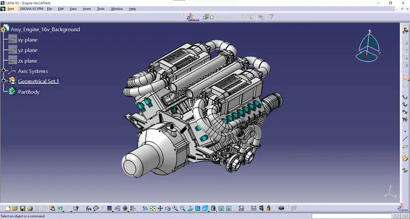
ENGINE:
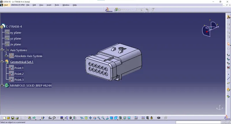
CONNECTORS:
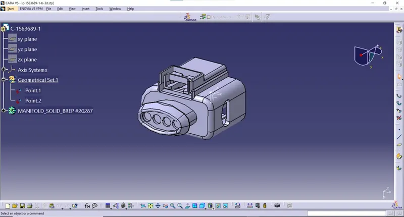
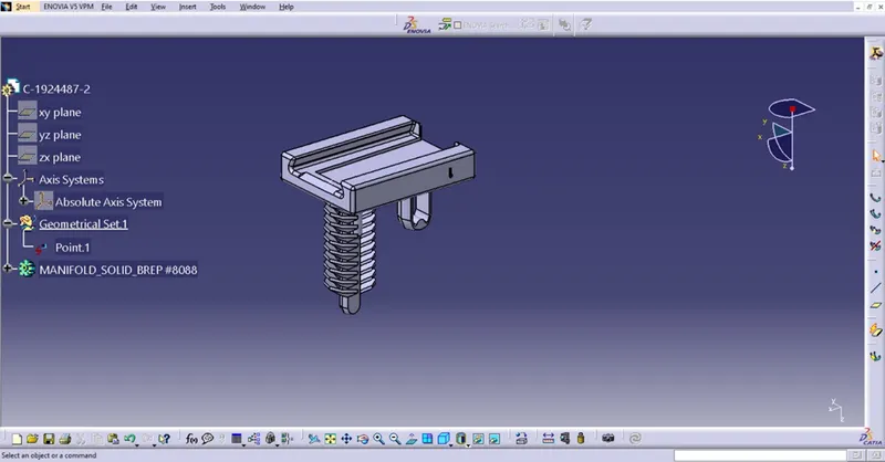
MOUNTING CLIP:
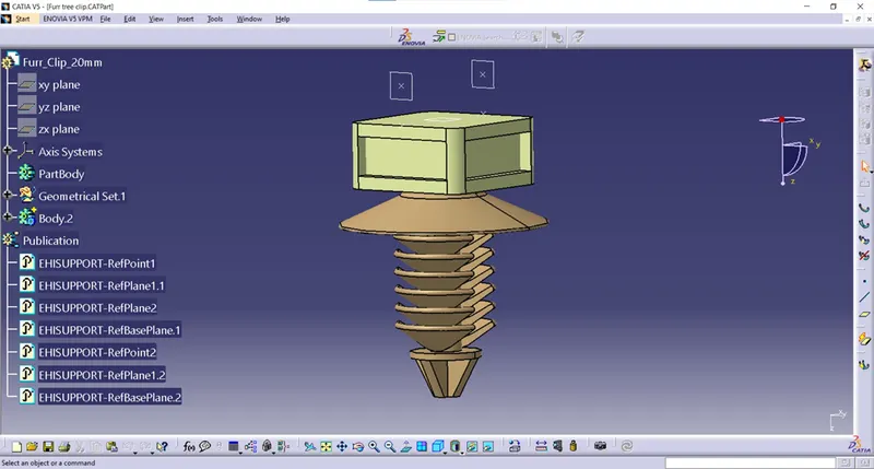
FUR TREE CLIP:
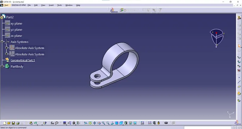
P – CLAMP:
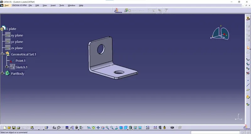
L SHAPED BRACKET:
GUIDNG CHANNEL:
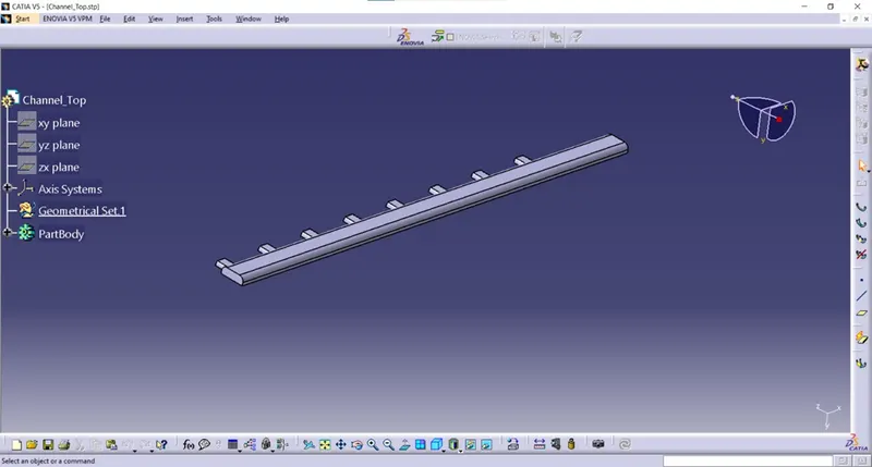
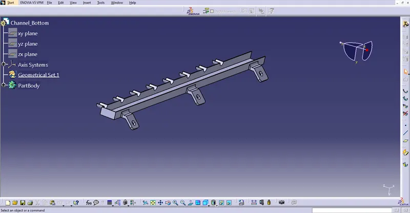
STEP 2: Define the mechanical components electrically and prepare the catalogue for the same:
C-282080-1 (2 pole connector):
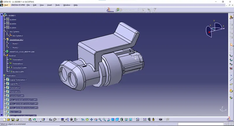
- Switch to part design workbench and created points at front face and mating face of the connector.
- Created axis system at the connector mating side.
- Switched to electrical part design work bench and defined the connector electrically by using the command called define connector and also created bundle connection point and connector connection point for the connector.
C-776438-4 (12 pole connector):
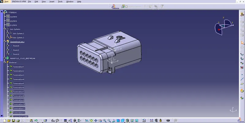
- Imported the stp file of the connector into Catia V5 and saved as a CATPART file.
- Switched to part design workbench and created points at the front face and mating face of the connector.
- Switched to electrical part design workbench and defined the connector electrically by using the command define connector.
- And also created the bundle connection point and connector connection point of the connector. And saved the connector file into the catalogue which is already created and saved into the device.
C-1563689-1(4 pole connector):
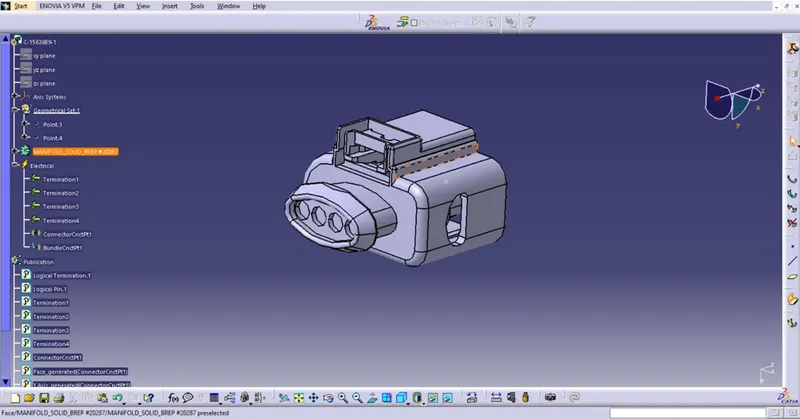
- Imported the stp file of the connector into Catia V5 and saved as a CATPART file.
- Switched to part design workbench and created points at the front face and mating face of the connector.
- Switched to electrical part design workbench and defined the connector electrically by using the command define connector.
- And also created the bundle connection point and connector connection point of the connector. And saved the connector file into the catalogue which is already created and saved into the device.
MOUNTING DEVICE:
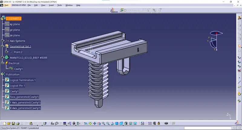
- Imported the stp file of the mounting device and saved as a CATPART file.
- Switched to the part design workbench and created a point at the mating face of the mounting device. And also created the axis system the mating face.
- The mounting device is defined electrically by using the command called define equipment.
- And created cavity to the mounting device by using the command called define cavity. And saved the file into the catalogue.
FUR TREE CLIP:
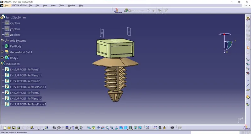
- imported the STP file of the fur tree clip and saved the file as a CATPART file.
- Switched to part design workbench and created the point at both sides of the clip as an entry point and exit point of the clip.
- And also created the planes at the points which we are created earlier as an entry plane and exit plane of the clip and base plane on the surface of the clip.
- Switched to the electrical part design workbench and defined the clip electrically by using the command Define support part and defined the first plane, second plane and base plane.
P- CLAMP:
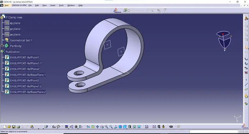
- imported the STP file of the fur tree clip and saved the file as a CATPART file.
- Switched to part design workbench and created the point at both sides of the clip as an entry point and exit point of the clip.
- And also created the planes at the points which we are created earlier as an entry plane and exit plane of the clip and base plane on the surface of the clip.
- Switched to the electrical part design workbench and defined the clip electrically by using the command Define support part and defined the first plane, second plane and base plane.
GUIDING CHANNEL:
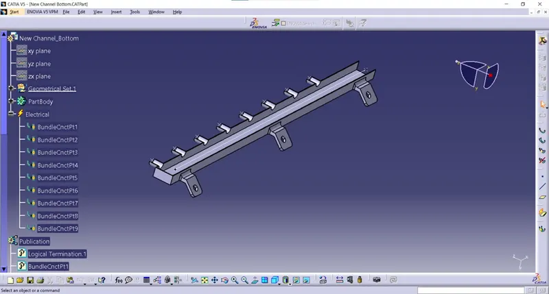
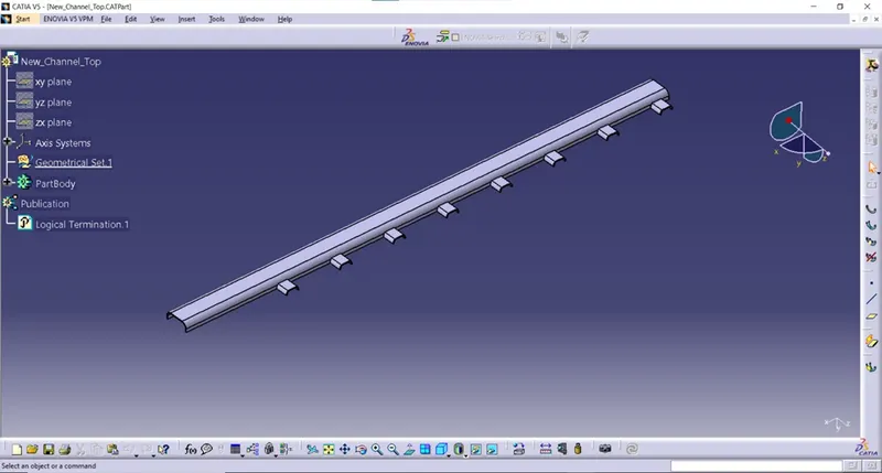
- Imported the channel bottom file into the Catia V5 and saved as a CATPART file.
- Switched to the part design workbench and created points at the open face of the channel and end face of the channel for the bundle entry.
- Then created the points at every slot of the channel for the bundle entry.
- Switched to electrical part design and defined the channel electrically by using the command define mounting equipment.
- And created the bundle connection point at the points which we are already created for the bundle entry.
STEP 2: CREATED WIRING HARNESS CONTEXT ASSEMBLY AND ADDING CONNECTORS INTO IT:
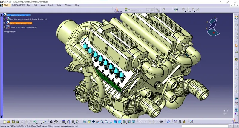
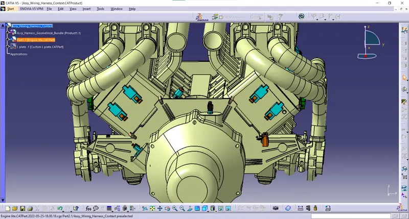
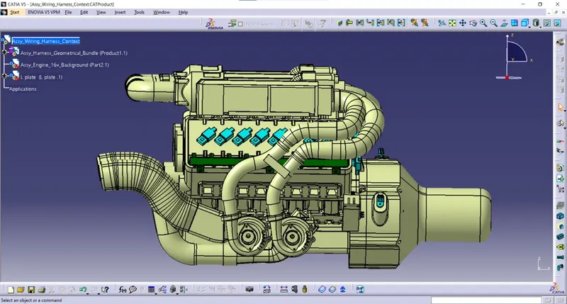
- Created a new product file for wiring harness context assembly.
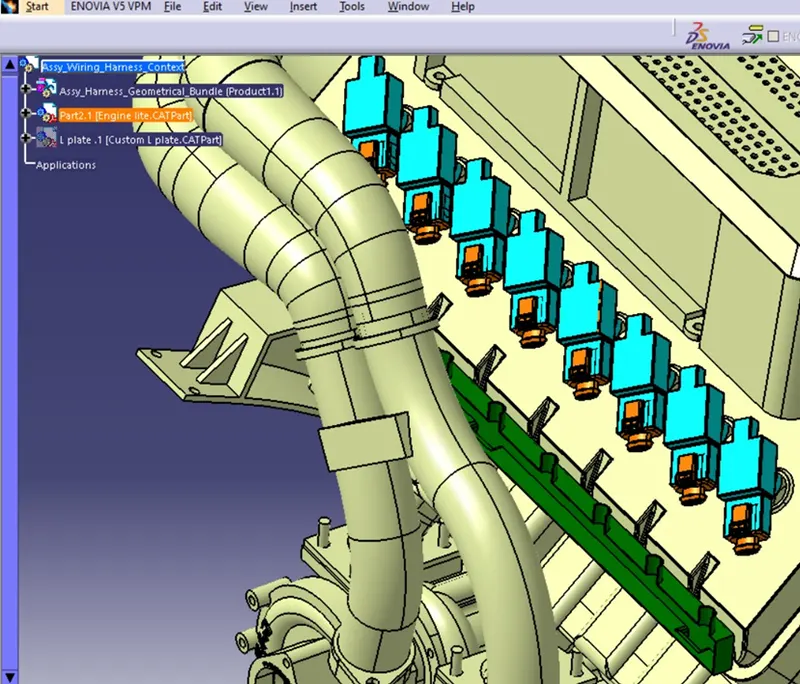
- And added a new product file into the wiring harness context assembly and named as Assy_Harness_Geometrical_Bundle. And added all the required connectors into the Assy_Harness_Geometrical_Bundle.
- And aligned the required connectors into the fuel injector sensors and cam shaft sensors.
STEP 3: ADDING SHEET METAL BRACKET:
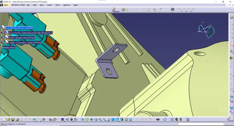
- The sheet metal bracket is added into the Assy_Harness_Geometrical_Bundle file and aligned and placed it with one of the bolts of the engine by using the command such as manipulate, snap, smart move features in the assembly workbench.
STEP 4: MOUNTING THE INTERCONNECTIION CONNECTOR WITH THE MOUNTING DEVICE ON THE SHEET METAL BRACKET.
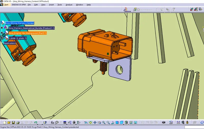
- The interconnection connector (C-776438-4) and the mounting device is added into the Assy_Harness_Geometrical_Bundle product file.
- It is aligned and placed on the sheet metal bracket by using commands such as manipulate, snap and smart move features in the assembly design workbench.
- Then switched to electrical assembly design workbench and connected the mounting device and the interconnection electrically by using the command known as Connect Electrical Devices.
STEP 5: ADDING P- CLAMPS INTO THE ASSY_HARNESS_GEOMETRICAL_BUNDLE FILE:
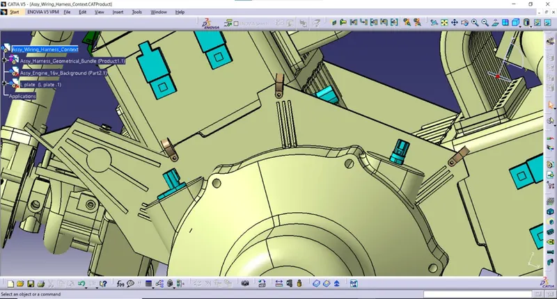
- Required number of P-Clamps are added into the Assy_Harness_Geometrical_Bundle file.
- The P clamps are mounted to the bolts of the engine by using the commands such as manipulate, snap, smart move features available in the assembly design workbench.
STEP 6: ADDING THE GUIDING CHANNELS INTO THE ASSEMBLY FILE:
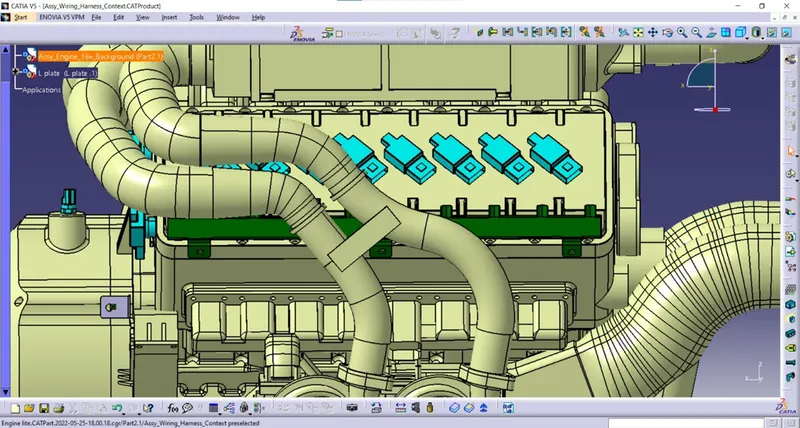
- The guiding channel is already defined electrically and added it into the Assy_Harness_Geometrical_Bundle file.
- It is arranged and mounted on the engine which is nearer to the engine sensors for maintaining the harness bundles with the connectors placed in the engine sensors.
- It was mounting by using the features called manipulate, snap, and smart move which is available in the electrical assembly design workbench.
STEP 7: ROUTING THE BUNDLE FROM THE INTERCONNECTION CONNECTOR TO THE P CLAMPS:
- Switched to the Electrical Harness Workbench.
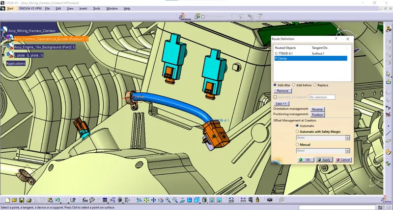
- The Assy_Harness_Geometrical_Bundle file is defined electrically by using the command Define Geometrical Bundle available in the Electrical Harness Assembly Work bench.
- For creating the branches, selected the multibranchable Document command.
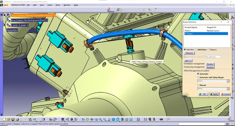
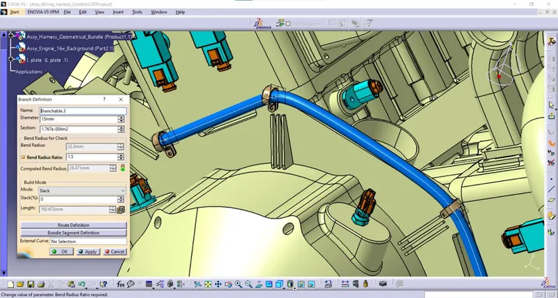
- The diameter of the branch is 15mm and bend radius ratio should be 1.5
- In the routing definition, selected the interconnection connector and the P clamp which is shown in the below figure.

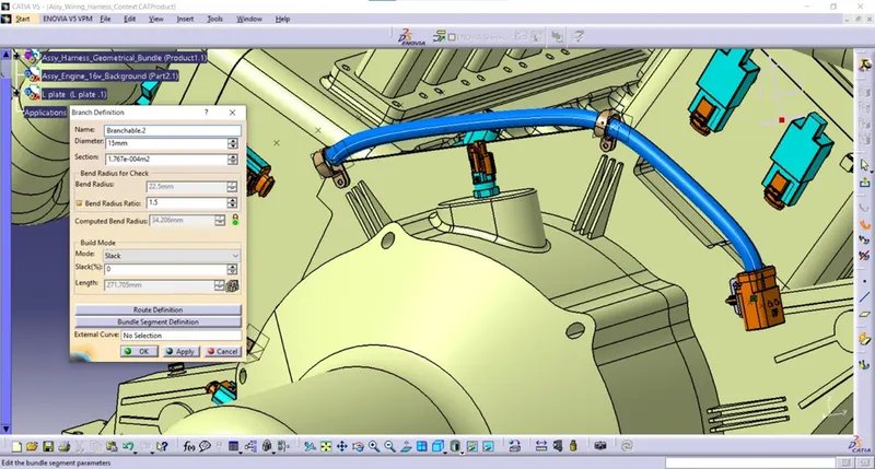
- Now we created the second branch from that p clamp to the next p clamp by selecting the branch definition command in the electrical harness installation workbench.
- The bundle diameter is changed to 15mm and bend radius ratio is changed to 1.5
- In the routing definition, selected the bundle and next p clamp.
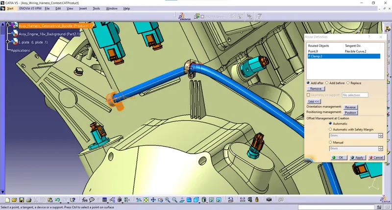
- Now we created the branch from the second p clamp to the third p clamp by selecting the branch definition command available in the electrical harness installation workbench.
- The bundle diameter is set to mm and bend radius ration is assumed to 1.5
- In the routing definition, selected the bundle at the second p clamp and the next p clamp.
STEP 8: ADDING THE BRANCH POINTS AND ROUTING THE BRANCHES FROM MAIN TRUNK TO THE CAM SHAFT SENSORS:
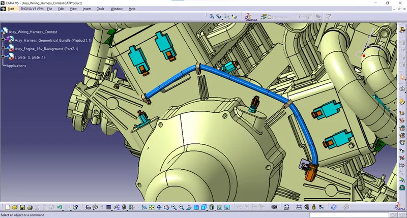
- Added the branch points in the main trunk for creating the sub branches to the cam shaft sensors from the main branch.
- Branch point is added in the main trunk by using the command known as add branch point available in the electrical harness installation workbench and select the required branch.
- Now place the point on the branch by giving the length value or ratio value.
- Totally six branch points were added into the main trunk for creating sub branches for the camshaft sensors and other sensors nearer to the main trunk.
STEP 9: ROUTING BRANCHES FROM THE BRANCH POINT TO THE NEAREST CAM SHAFT SENSORS:
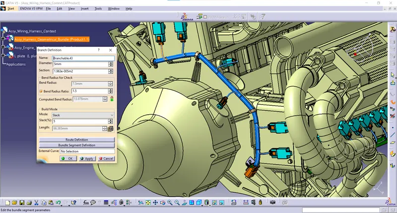
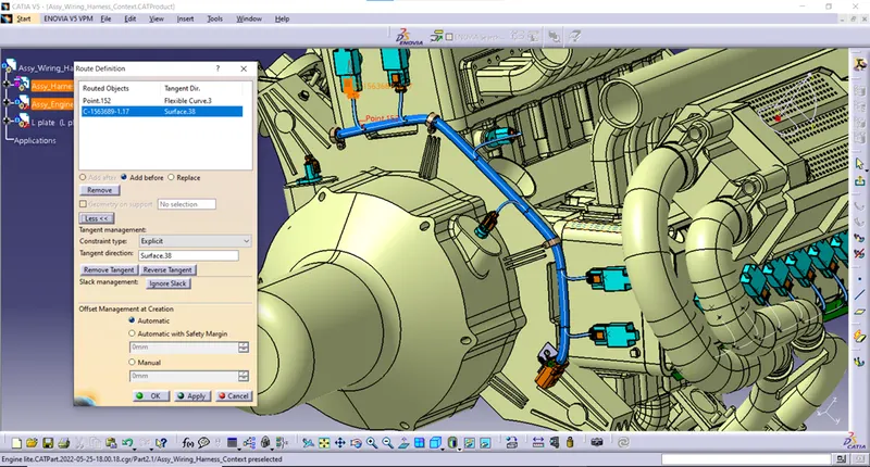
- Now the sub branch is created from one of the branch points in the main trunk to the cam shaft sensor by selecting the branch definition command in the electrical harness installation work bench.
- The diameter is set to 5mm and the bend radius ratio is set to 1.5 and provided some amount of slack to the branch to avoid the bending issues of the bundle.
- Now in the routing definition, the branch point and the cam shaft connector is selected which is shown in the below figure.
- By using the same process, created the sub branches to other connectors from the branch points on the main trunk of the harness.
STEP 10: ADDING FIR TREE CLIPS AND ROUTING BRANCHES FROM THE MAIN BRANCH TO THE GUIDING CHANNEL THROUGH THE FUR TREE CLIP:
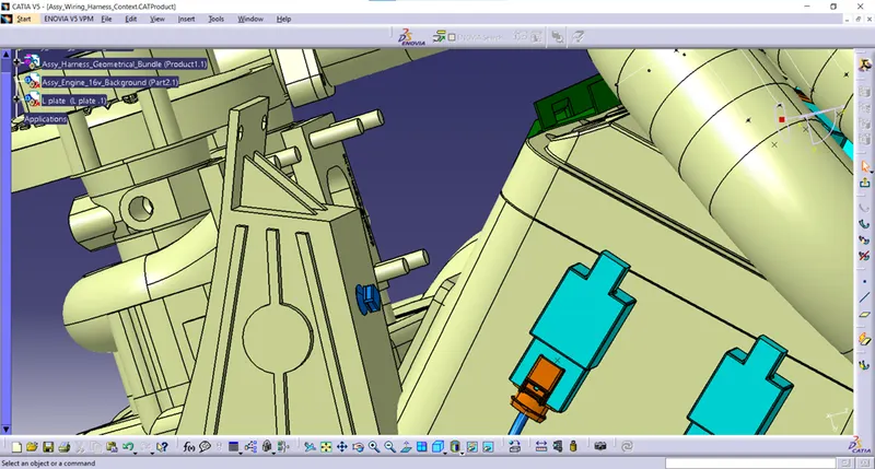
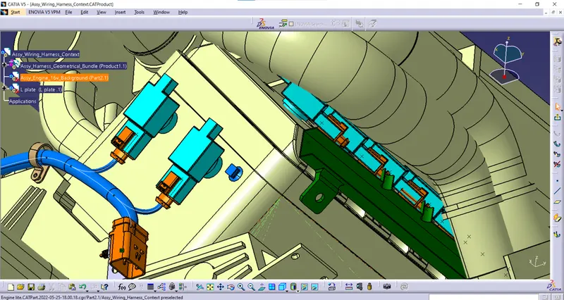
- Now the fIr tree clip is added into the Assy_Harness_Geometrical_Bundle.
- The fur tree clip was arranged and placed on the engine surface which is nearer to the guiding channel to avoid any other branch bending issues.
- One more fur tree clip is placed on the other side of the engine nearer to another guiding channel which is mounted on the engine.
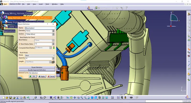
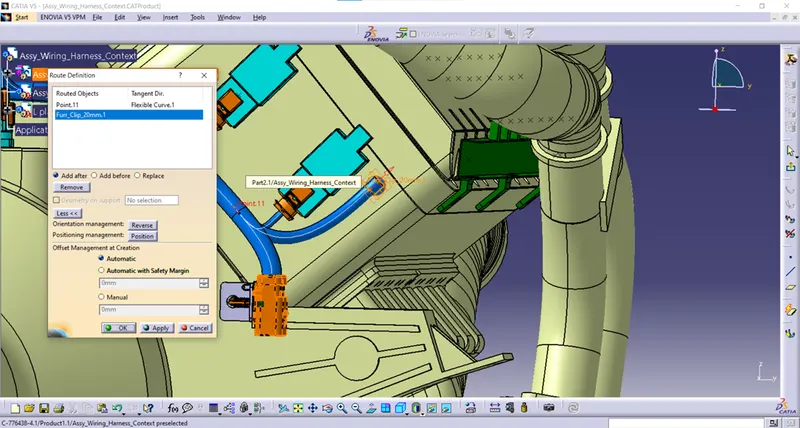
- now the branch is created from one of the branch points in the main trunk to the fur tree clip by using the command branch definition in the electrical harness installation work bench.
- The diameter of the branch is set to 10mm and the bend radius ratio is set to 1.5 and provided 10% of slack to the bundle.
- In the routing definition, selected the branch point which is nearest to the interconnection connector and fIr tree clip which is shown in the below.
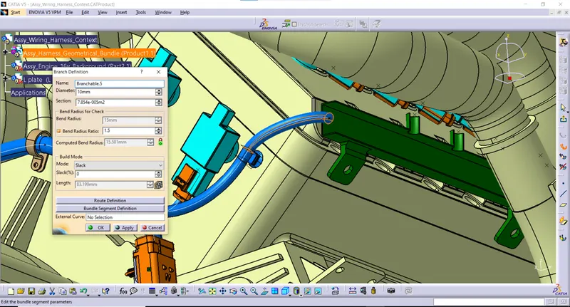
- Now the bundle is routed from the fur tree clip to start of guiding channel by using branch definition command in the electrical harness installation work bench.
- The fur tree clip is provided for the smooth path of the bundle without creating any issues while routing to the guiding channel.
- The diameter of the bundle is 10mm and the bend radius ratio is 1.5
- Now the branch is routed from the start of guiding channel to the end of the guiding channel with the help of external curve which is already created into the guiding channel.
- The branch is created by using branch definition command available in the electrical harness installation workbench.
- The diameter is set to 10mm and bend radius ratio is 1.5
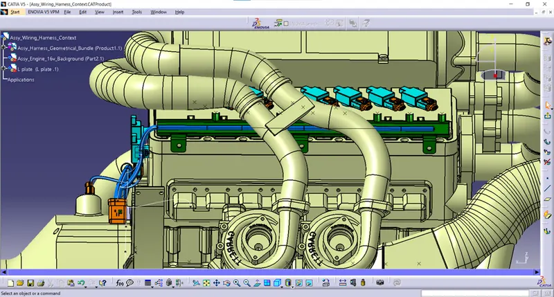
- By using the above process, the bundle is routed to the guiding channel at the another of the engine through the fur tree clip.
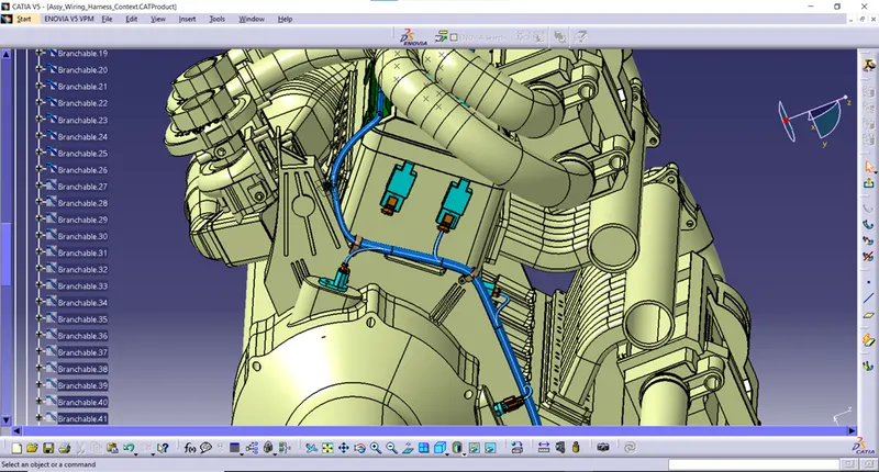
STEP 11: ADDING BRNACH POINTS TO THE BUNDLE IN GUDING CHANNEL AND ROUTING THE BRANCHES FROM THE BRANCH POINTS TO CONNECTORS PLACED ON THE FUEL INEJCTOR SENSORS OF THE ENGINE:
- Now the branch points is added to the bundle which is inside the guiding channel.
- Totally seven branch points were added into the branch inside the guiding channel by using add branch point command in the Electrical harness installation workbench.
- And also added the branch points to the bundle inside the guiding channel which is mounted on another side of the engine.
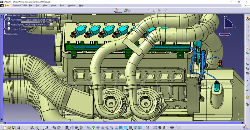
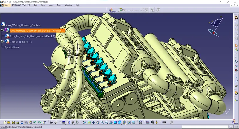
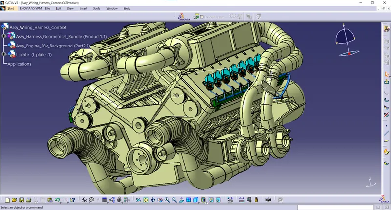
- Now the bundles are routed from the branch points located on the branch inside the guiding channel to the connectors placed on the fuel injector sensors by using the branch definition command in the electrical harness installation work bench.
- The diameter of the sub branches is 5mm and bend radius ratio is 1.5 and provided some percentage of slack to reduce the tension to the branches routed to the connectors.
STEP 12: ADDING PROTECTIVE COVERINGS TO THE BUNDLES:
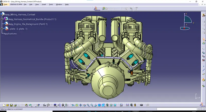
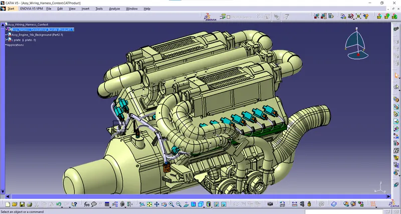
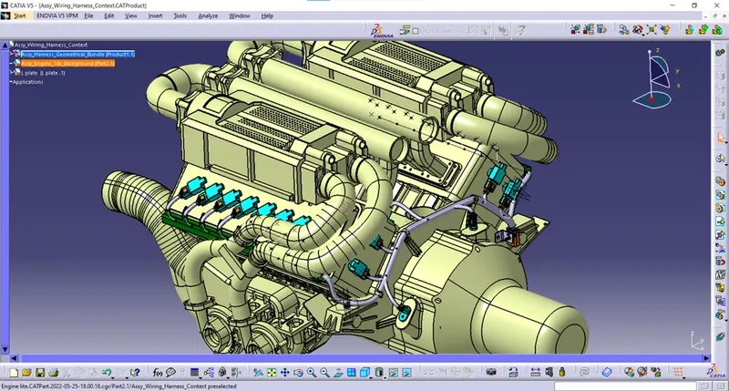
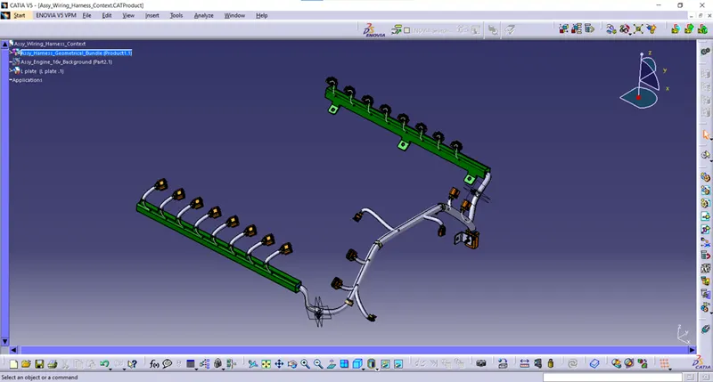
- Protective coverings are added to the bundles such as cot tubes with different diameters according to the bundle diameters.
- Protective covering is applied to protect the branches from the heat coming out from the engine and also protecting bundles from the sharp edges if any.
- It also gives an nice appearance to the wiring harness.
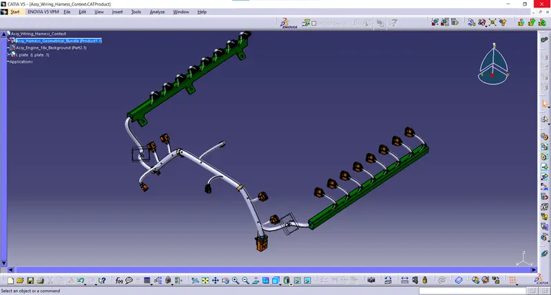
STEP 13: CHECKING BUNDLE CONTUINITY:
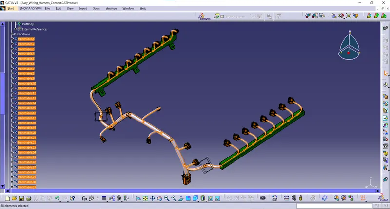
- Here we need to select the multi branchable in the model tree and we have to go to Edit > Search > Advanced > Workbench – Electrical > Type – Bundle segment > Attribute – Fully connected.
- And there are two options which are true and false.
- By selecting the ‘True’ option, it will show all the bundles connected electrically. By selecting False option, it will show all the bundles which not connected electrically.
- Now we selected the ‘True option’ and searched for the results. It highlights all the bundles which are connected electrically as shown in the below figure.
STEP 14: CREATING FLATTEN VIEW OF THE WIRING HARNESS BUNDLE:
- Created a new product file for flattening the wiring harness assembly and renamed as a Assy_Engine_Harness_Flattening.
- we need to switch to the electrical harness flattening workbench to create the flatten view of the wiring harness assembly.
- Ensure that the flattening file of the wiring harness assembly is saved in the same location where the wiring harness context assembly is saved.
- Now the first step is to define the flattening parameters by selecting the Harness Flattening Parameters command in the Electrical harness flattening work bench.
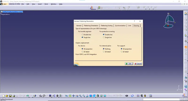
- In the drawing section, select the single line for bundle segment and double line for protective covering.
- Then the Assy_Harness_Geometrical_Bundle file from the context assembly is extracted into the Assy_Engine_Harness_Flattening file by using the extract command in the electrical harness installation work bench.
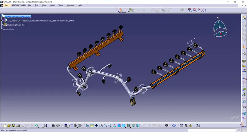
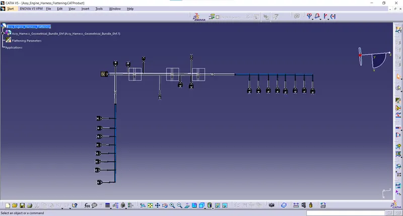
- Now the file is flattened by using the Flatten command in the electrical harness installation workbench which is shown in the below figure.
- The assembly geometrical bundle file is flattened with reference plane of the guiding channel surface.
- After flattening, the fur tree clips and p-clamps are mislocated from their respective locations. Then it was aligned and arranged by using manipulate, snap and smart move features by switching to assembly design work bench.
- And also, the branches were tilted to some different angle after flattening. Then the branches were aligned in a straight way and in perpendicular direction with the main branch by using the rotate command available in the electrical harness flattening work bench.
STEP 15: CREATING DRAWING FILE FOR WIRING HARNESS ASSEMLY ROUTING FILE:
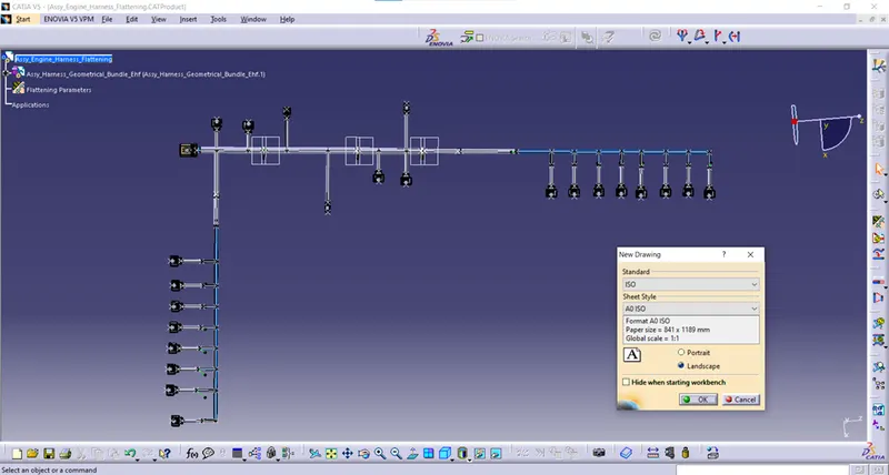
- File > New > Drawing > ok
- After that, defined some parameters for drawing file.
- Then the flatten product file was converted into drawing file by select the front view command in the electrical harness flattening work bench.
- After selecting the front view command, then selected the top face of the interconnection connector as a front view of drawing file which is shown in the below figure.
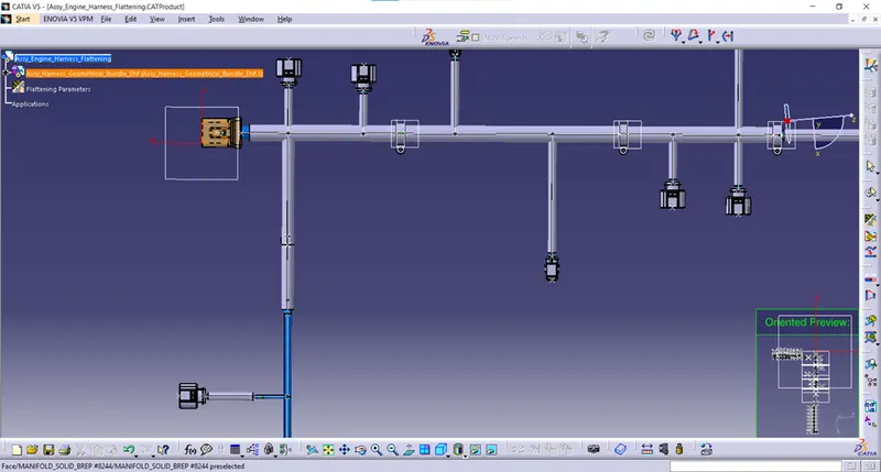
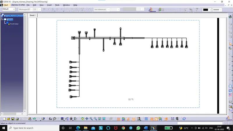
- After selecting the front view as a top surface of interconnection connector, the flattened file in converted into the drawing file which is shown below figure.
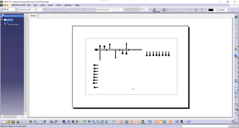
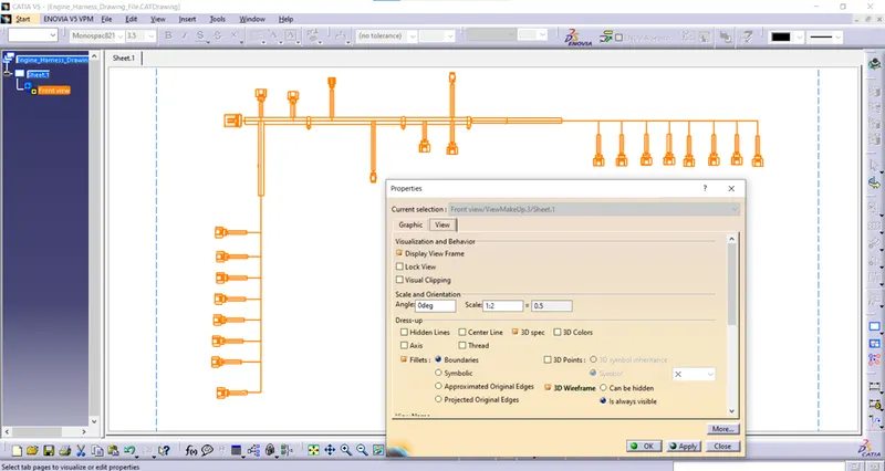
- After converting into drawing file, the bundles are not represented in the drawing file.
- To enable the bundle representation, we need change some properties.
- In the properties, under view tab, in the dress-up section, the 3D wireframe option is not enabled by default.
- We need to enable the 3D wireframe is always visible.
- The connectors are represented in 3D by modifying the harness flattening parameters in the electrical harness installation workbench.
CONCLUSION:
In this way, the wiring harness for Bugatti V-16 engine was routed. And also prepared the flatten in the ‘Electrical Harness Flattening work bench’ and prepared the drawing file for the flattened file in Catia V5.