Project 1
Objective:
The objective of this project is to create the routing for the given Engine and prepare to flatten the view drawing in CATIA V the mechanical part as an electrical connector and apply the electrical properties to the Connectors.
Procedure:
Procedure for Connector Definition:
• Initially, the mechanical model of the required connectors is downloaded.
• After that, the downloaded source file (Stp/lgs) is converted into CAT Part.
Connector Definition:
1) Create/Download Connector 3D
2) Create required Geometrical Parameters
• In the third step the required reference points like Bundling entry point, Connector connection point, and Cavity connection point.
• Also, the required axis system for the Connector and Cavity is created.
3) Define part as Connector
• The parts are defined as connectors by using the define connector" option in CATIA
• While defining the connector, depending on the connector number of the terminal is mentioned.
Connector Defination :
1. Create point and axis system for connector connection point and bundle connection point
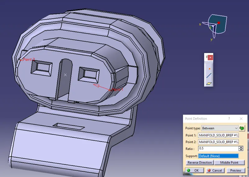
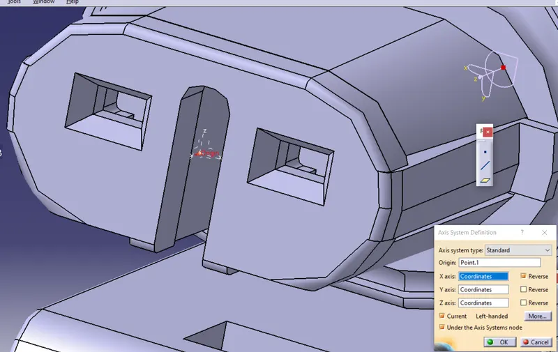
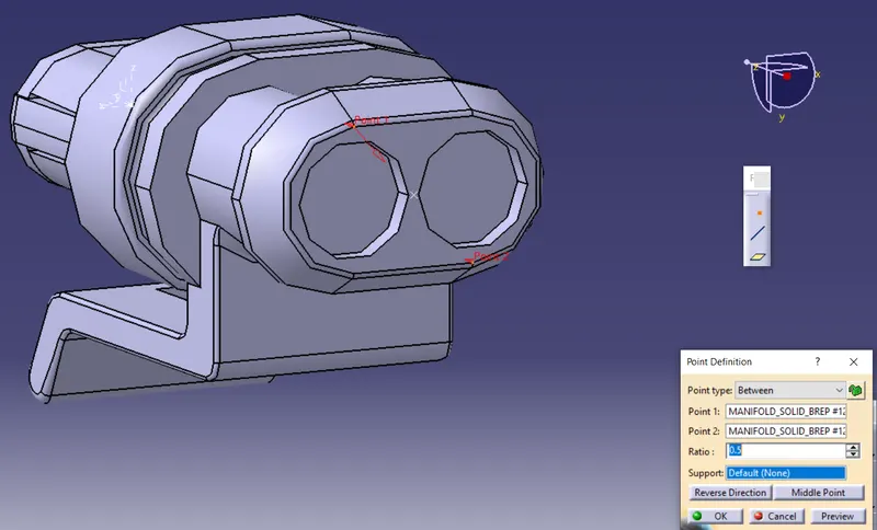
2. Define Connector for number of termination .
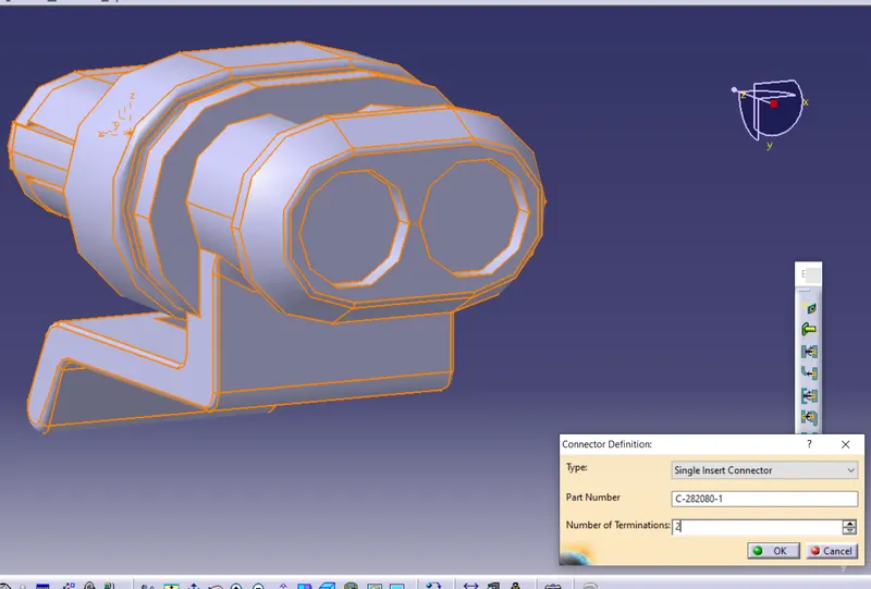
3. Define connector as electrical Defination giving CCP & BCP .
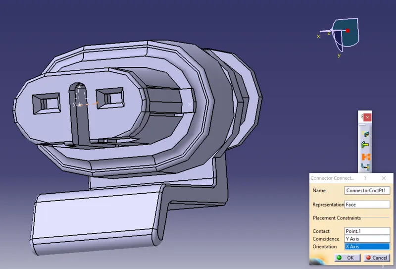
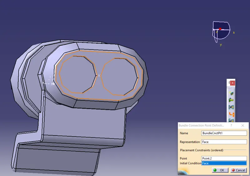
4. Define Cavity connection point with following parameter .
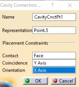
Cavity connection point is an optional part of connector .
These are few connector we used in assembly .
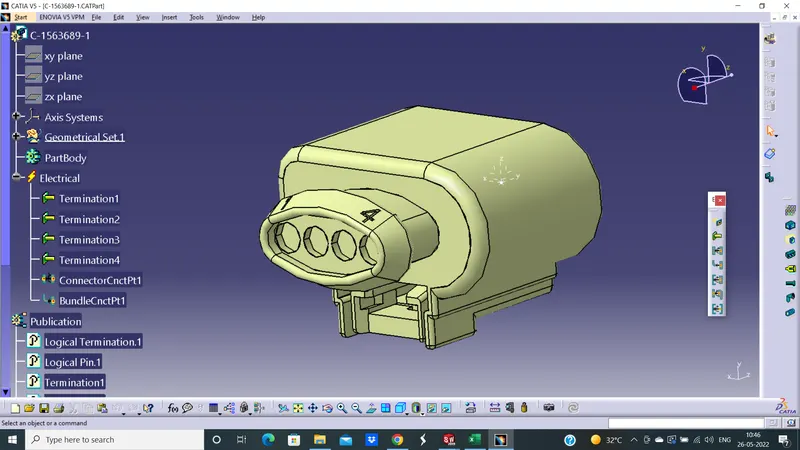
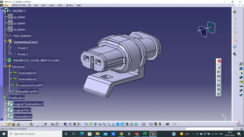
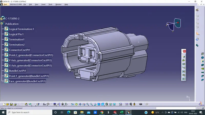
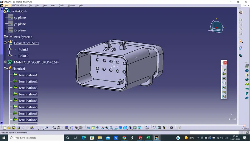
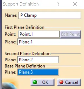
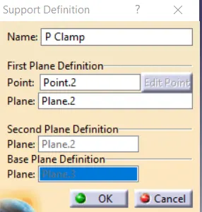
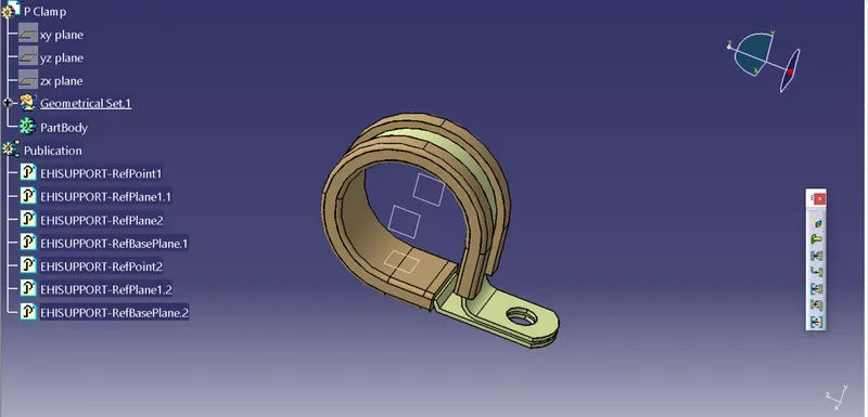
P Clamp Defination :
Procedure for P Clamp
initially, the mechanical model of the required connectors is downloaded .
After that, the downloaded source file (Stp/igs) is converted into CAT Part.
The geometrical parameters are applied to the electrical support
the entry point and plane are selected for the clamps use "deline support option
L CLAMP Procedure
initially, the mechanical model of the required connectors is downloaded .
After that, the downloaded source file (Stp/igs) is converted into CAT Part.
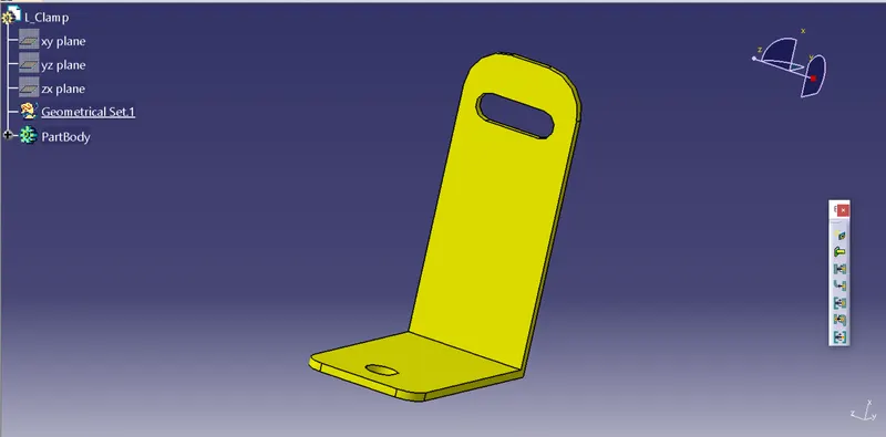
We use L Clamp As a mechanical part .
Furr Tree Clip
initially, the mechanical model of the required connectors is downloaded .
After that, the downloaded source file (Stp/igs) is converted into CAT Part.
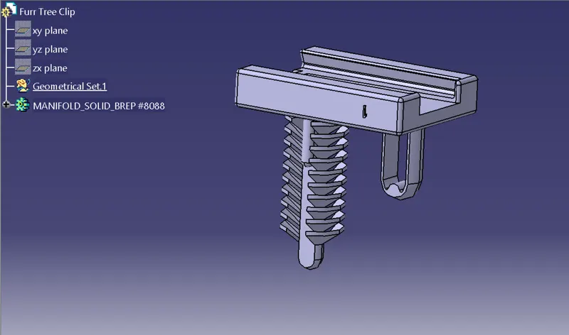
We use Furr tree clip As a mechanical part .
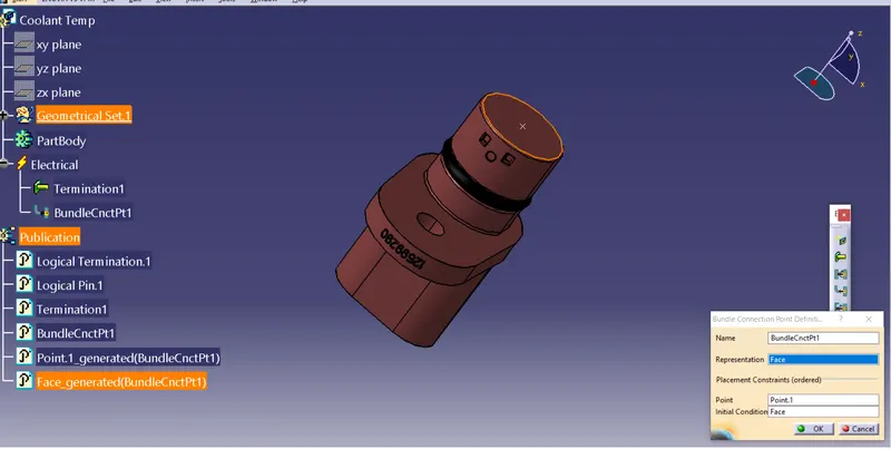
Define Coolant Temprature Sensor .
initially, the mechanical model of the required connectors is downloaded .
After that, the downloaded source file (Stp/igs) is converted into CAT Part.
Giving coolant only bundle connection point .
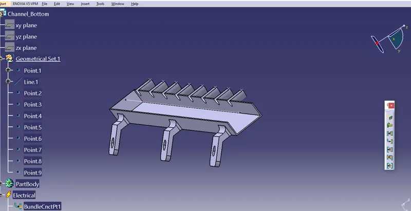
Bottom Channel
initially, the mechanical model of the required connectors is downloaded .
After that, the downloaded source file (Stp/igs) is converted into CAT Part.
The Geometrical parameter is electrical mounting equipment .
Defined as mounting equipment and given bundlle connection point .
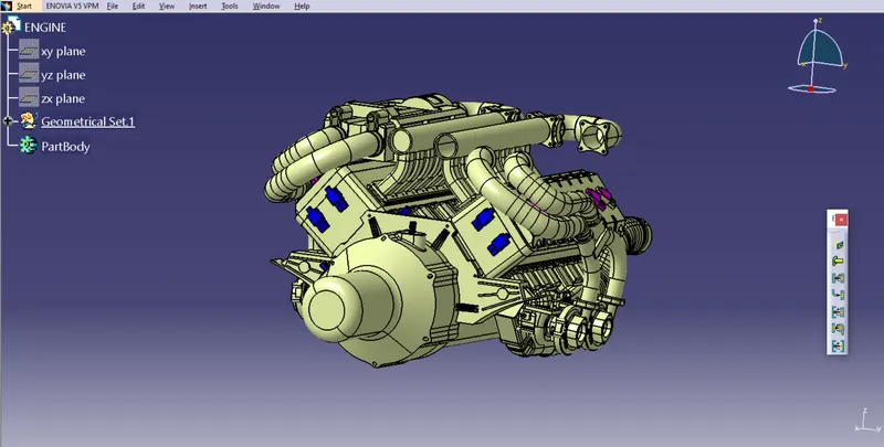
ENGINE File
initially, the mechanical model of the required connectors is downloaded .
After that, the downloaded source file (Stp/igs) is converted into CAT Part.
Engine file is used as a mechanical part having multiple area where we have to established the connector , sensor , & P clamp
for wire routing .
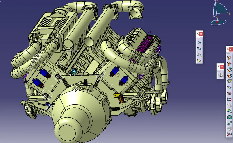
Create Assembly
Procedure :
1. for createing a new assembly go to NEW(ctrl+n)>Assembly click ok
2.Rename it ' ENGINE CONTEXT ASSEMBLY '
3. Drag Engine file or Assembly workbench > existing component icon > Engine Context Assembly > open file > Engine
4. Assembly Workbench > product icon > Engine Context Assembly create new product in assembly file .
5. Rename new product as Engine Geometrical Bundle
6. Existing component > Engine Geometrical Bundle > Connector , P Clamp , Sensor
All parts come one by one
7. Placed all component on there respective position .
ELECTRICAL HARNESS ASSEMBLY
1. Go to EHA workbench > Geometrical bundle icon Convert the mechanical assemble in electrical assembly .
2. Define the rounting area for the bundlle , from interconnection connector to other connector via P clamp & channel .
3. Define the Diameter and bend radius to bundle segment .
4. If necessary giving slack to bundle segment .
5. Used branch point for a defined path to a connector .
6. Used protecting cover for bundle segment .
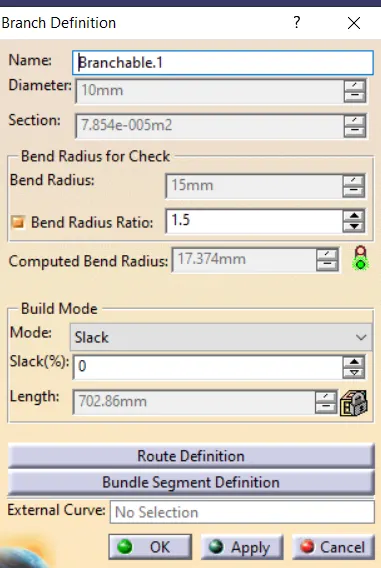
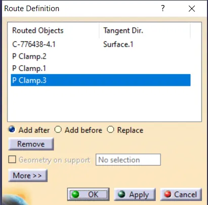
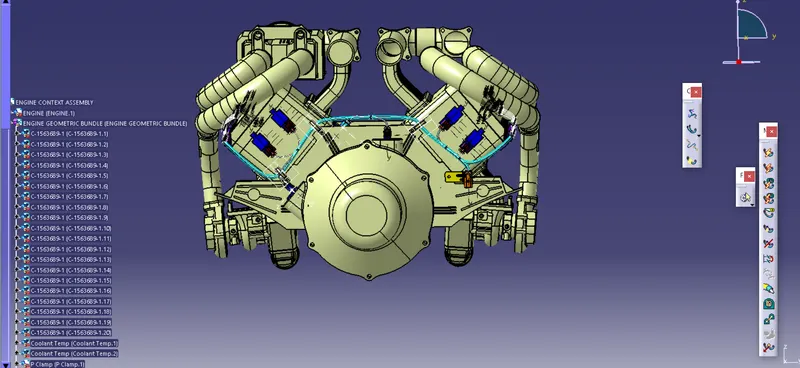
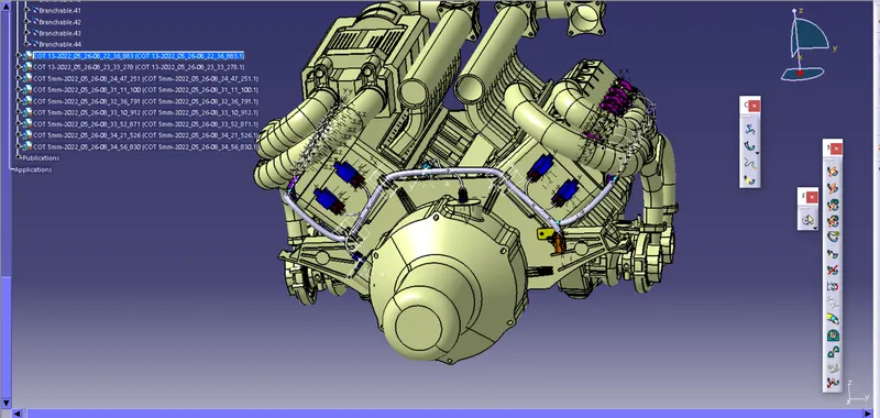
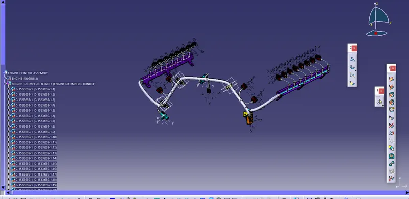
Check the Connection point
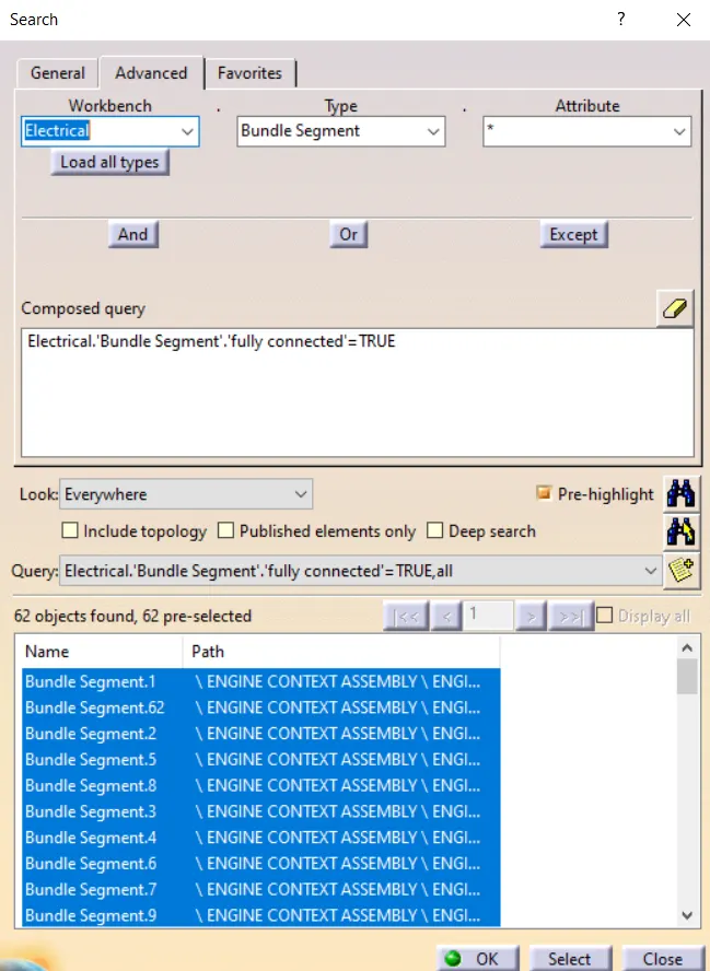
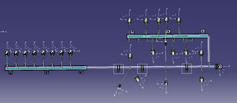
ELECTRICAL HARNESS FLATTENING
1. Create new product
2. Set Falttening Parameter
3. Import bundlle segment from Engine context assembly .
4. Use Flattening icon for flatten the bundle taking a flat surface or plane as reference .
5. Adujust all component .
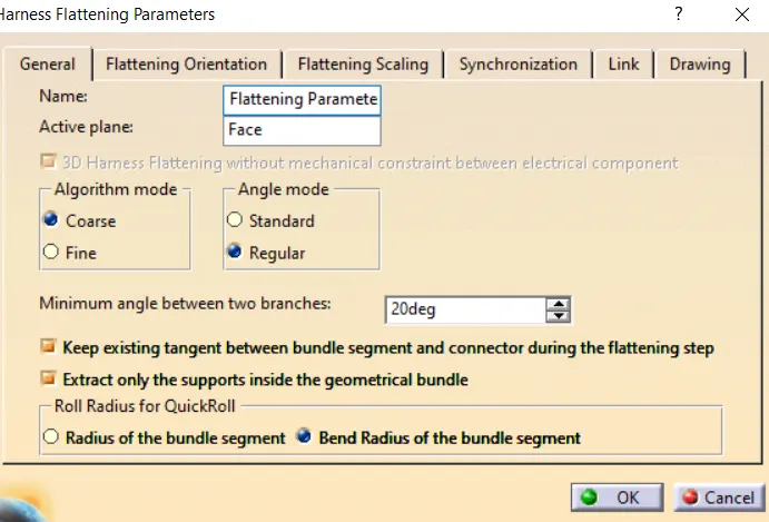
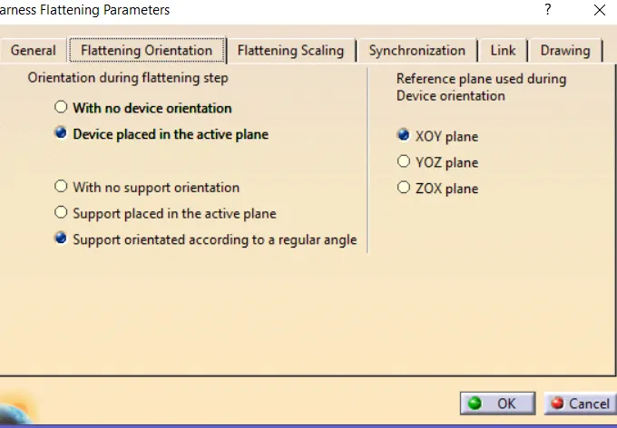
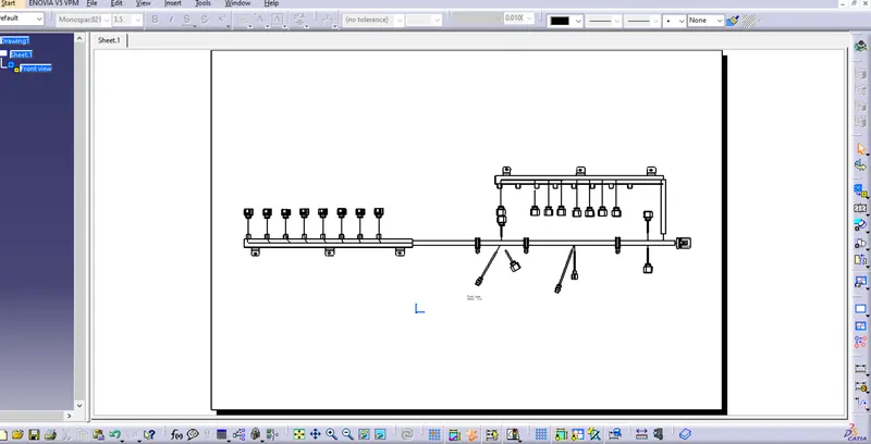
Drawing Procedure
1. ctrl+N > Drawing
2.Select Front Plane > Flattening Assembly > Face/Plane ( projected view )
3. Adust bundle by rotation or up/down/left/right
4. place bundle for final result .
Conclusion:
The Routing is created for the given model by using the different workbenches in CATIA like Part Design, Assembly Design. Electrical Part design, Electrical Harness Assembly, etc.