Week 1 Challenge 2
AIM:
To analysis various beams by using finite element analysis process.
Objective:
The aim of this project is to analyze the performance of three different types of beams under the same bending compare the results for stress, displacement and strain and choose the most efficient beam out of the three.
Theory:
The beam, or flexural member, is frequently encountered in structures and machines and its elementary stress analysis constitutes one of the more interesting facets of mechanics of materials. A beam is a member subjec loads applied transverse to the long dimension, causing the member to bend.
Various types of beams are used in structural applications, the most common ones being simply supported be beam with overhang, continuous beam, cantilever beam, beam fixed (or restrained) at one end and simply supported near the other end, beam fixed (or restrained) at both ends etc. In this project, all the beams that are analyzed are of cantilever type with a different cross-section in each case.
A cantilever beam is one in which one end is built into a wall or other support so that the built-in end cannot m transversely or rotate. The built-in end is said to be fixed if no rotation occurs and restrained if a limited amoun rotation occurs.
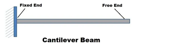
Cantilever beams have two reactions (two forces or one force and a couple) and these reactions can be obtai from a free-body diagram of the beam by applying the equations of equilibrium. Such beams are said to be statically determinate since the reactions can be obtained from the equations of equilibrium.
Stress
Determination of stress distribution of beam in necessary for determining the level of performance of the beams. In particular, stress-based failure theories require determination of the maximum combined stresses
Deflections
Often limits must be placed on the amount of deflection a beam or shaft may undergo when it is subjected to a load. For example beams in many machines must deflect just the right amount for gears or other parts to make proper contact. Deflections of beams depend on the stiffness of the material and the dimensions of the beams, as well as the more obvious, applied loads and supports.
Strain
Although strain is not usually required for engineering evaluations (for example, failure theories), it is used in the development of bending relations.
Procedure:
The entire process of performing a Solidworks simulation can be divided into four parts.
1. Part design
Includes making the cad model of the system that is to be analyzed and assigning materials to the components.
2. Setting up of boundary conditions
Includes setting up the fixed supports, reactions and external loads.
3. Meshing
The type, size and various other mesh parameters are setup.
4. Solver Analysis
The solver is run giving out the results for Von mises stresses, strains and displacements at all the nodes and identifying the minimum and maximum values of those to determine the critical regions.
Simulation Process:
1. Beams under analysis (Part Design)
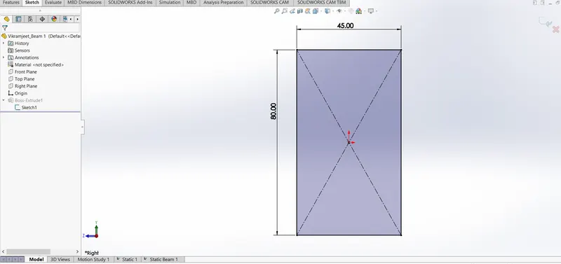
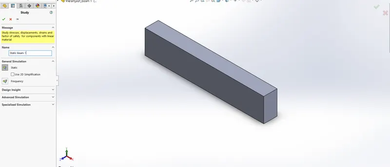
Beam 1: Rectangular beam
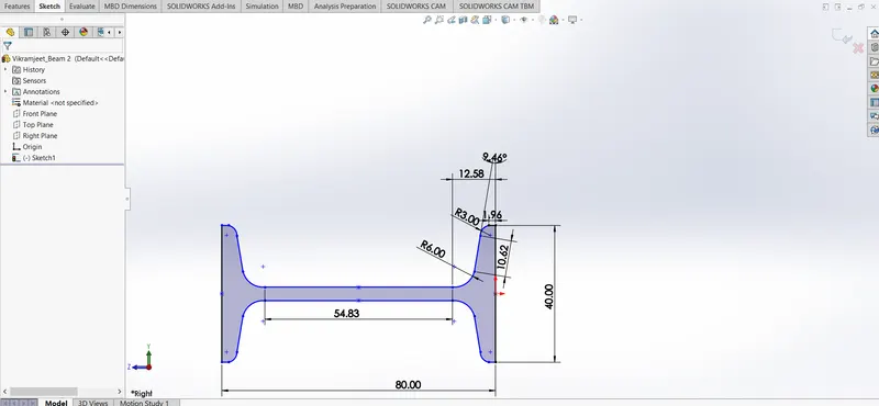
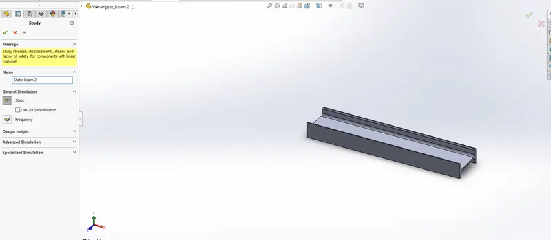
BEAM 2 :- Section Beam
BEAM 3 :- Section Beam
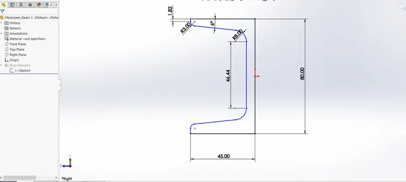
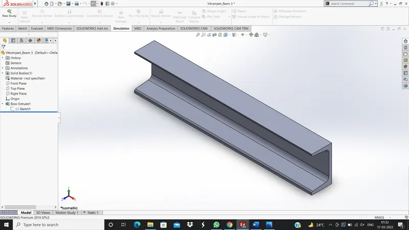
All the beams are extruded by their cross-section to a length of 400mm.
Material properties:
For comparison, all the beams are considered to be composed of the same material - Alloy steel, the properties of which are given below.
Name: Alloy Steel
Model type: Linear Elastic Isotropic
Default failure criterion: Max von Mises Stress
Yield strength: 6.20422e+08 N m²
Tensile strength: 7.23826e+08 N m²
Elastic modulus: 2.le+11 N m²
Poisson's ratio: 0.28
Mass density: 7700 k 9 m³
Shear modulus: 7.9e+10 N m²
Thermal expansion coefficient: 1.3e-05 /Kelvin
2. Boundary conditions and External loads:
Once the models have been developed, the next step is to establish fixtures and loads on the beams which are responsible for their bending.
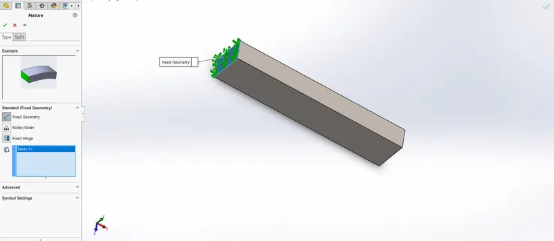
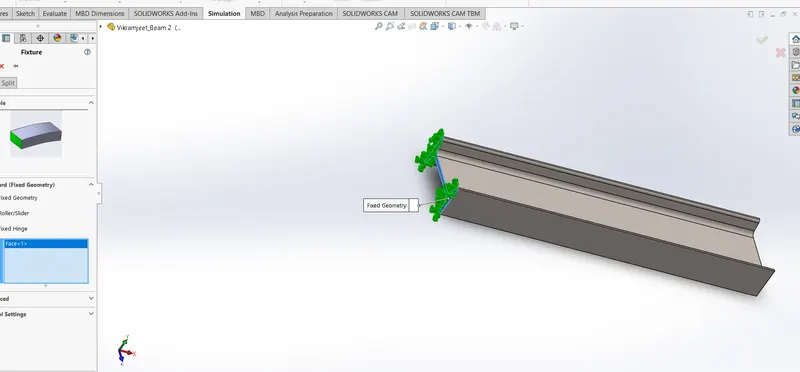
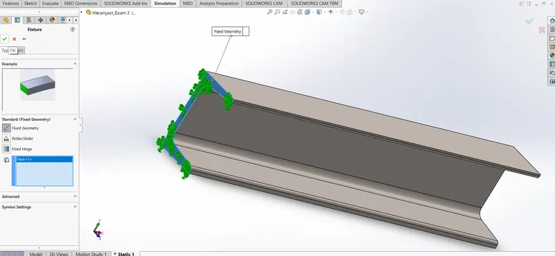
All the beams considered are of cantilever type and hence one side of the beam (short side) is chosen as fixed support and the other side is left free. The top surface is then loaded with a 1500N external load
The loading conditions of the beams are shown in the figures below.
Beam 1: Rectangular beam
Beam 2 : Section Beam
Beam 3 :- Section Beam
3 Meshing :-
Beam 1 :- Rectangular Beam
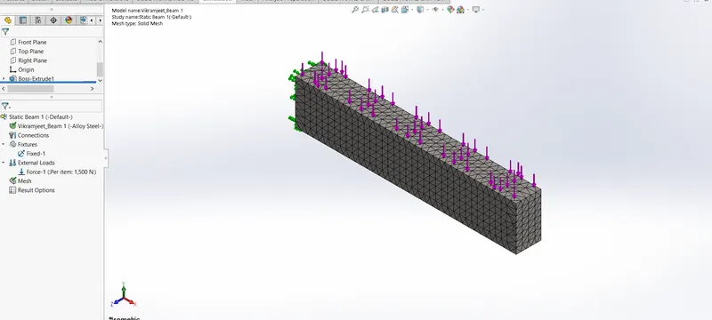
Mesh Information:
|
Mesh type |
Solid Mesh |
|
Mesher Used: |
Standard mesh |
|
Automatic Transition: |
On |
|
Include Mesh Auto Loops: |
Off |
|
Jacobian points |
4 Points |
|
Element Size |
11 mm |
|
Tolerance |
0.55 mm |
|
Mesh Quality Plot |
High |
Mesh information - Details
|
Total Nodes |
10820 |
|
Total Elements |
6765 |
|
Maximum Aspect Ratio |
4.3767 |
|
% of elements with Aspect Ratio < 3 |
99.8 |
|
% of elements with Aspect Ratio > 10 |
0 |
|
% of distorted elements(Jacobian) |
0 |
|
Time to complete mesh(hh;mm;ss): |
00:00:01 |
Beam 2 :- Section Beam
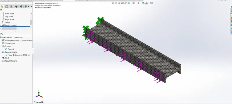
Mesh Information:
|
Mesh type |
Solid Mesh |
|
Mesher Used: |
Standard mesh |
|
Automatic Transition: |
Off |
|
Include Mesh Auto Loops: |
Off |
|
Jacobian points |
4 Points |
|
Element Size |
6.69533 mm |
|
Tolerance |
0.334767 mm |
|
Mesh Quality Plot |
High |
Mesh information - Details
|
Total Nodes |
18623 |
|
Total Elements |
9422 |
|
Maximum Aspect Ratio |
8.8138 |
|
% of elements with Aspect Ratio < 3 |
88.3 |
|
% of elements with Aspect Ratio > 10 |
0 |
|
% of distorted elements(Jacobian) |
0 |
|
Time to complete mesh(hh;mm;ss): |
00:00:04 |
Beam 3 :- Section Beam
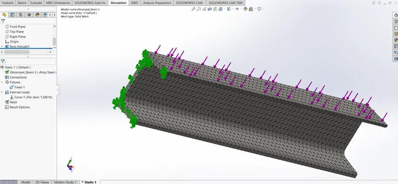
|
Mesh type |
Solid Mesh |
|
Mesher Used: |
Standard mesh |
|
Automatic Transition: |
Off |
|
Include Mesh Auto Loops: |
Off |
|
Jacobian points |
4 Points |
|
Element Size |
7 mm |
|
Tolerance |
0.35 mm |
|
Mesh Quality Plot |
High |
Mesh information - Details
|
Total Nodes |
19241 |
|
Total Elements |
10208 |
|
Maximum Aspect Ratio |
8.4557 |
|
% of elements with Aspect Ratio < 3 |
98 |
|
% of elements with Aspect Ratio > 10 |
0 |
|
% of distorted elements(Jacobian) |
0 |
|
Time to complete mesh(hh;mm;ss): |
00:00:02 |
Study And Result:
STUDY 1: Structural analysis of Rectangular Beam
Study name Static 1
Analysis type Static
Mesh type Solid Mesh
Thermal Effect: On
Thermal option Include temperature loads
Zero strain temperature 298 Kelvin
Include fluid pressure effects from SOLIDWORKS Flow Simulation Off
Solver type FFEPlus
Inplane Effect: Off
Soft Spring: Off
Inertial Relief: Off
Incompatible bonding options Automatic
Large displacement Off
Compute free body forces On
Friction Off
Use Adaptive Method: Off
Stress Plot
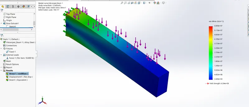
|
Name |
Type |
Min |
Max |
|
Stress1 |
VON: von Mises Stress |
6.445e+02 N/m^2 Node: 5418 |
7.734e+06 N/m^2 Node: 1 |
Displacement plot
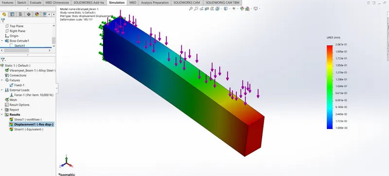
|
Name |
Type |
Min |
Max |
|
Displacement1 |
URES: Resultant Displacement |
0.000e+00 mm Node: 1 |
3.100e-02 mm Node: 499 |
Strain Plot
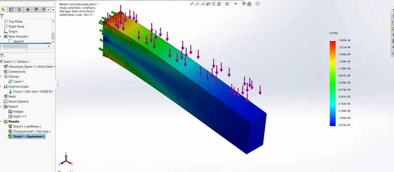
|
Name |
Type |
Min |
Max |
|
Strain1 |
ESTRN: Equivalent Strain |
2.358e-09 Element: 4582 |
2.365e-05 Element: 1859 |
STUDY 2: Structural analysis of I Section Beam
Study name Static 1
Analysis type Static
Mesh type Solid Mesh
Thermal Effect: On
Thermal option Include temperature loads
Zero strain temperature 298 Kelvin
Include fluid pressure effects from SOLIDWORKS Flow Simulation Off
Solver type FFEPlus
Inplane Effect: Off
Soft Spring: Off
Inertial Relief: Off
Incompatible bonding options Automatic
Large displacement Off
Compute free body forces On
Friction Off
Use Adaptive Method: Off
Stress Plot

|
Name |
Type |
Min |
Max |
|
Stress1 |
VON: von Mises Stress |
1.545e+03 N/m^2 Node: 18188 |
2.225e+07 N/m^2 Node: 1109 |
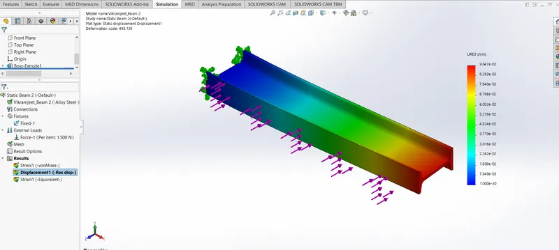
Displacent Plot
|
Name |
Type |
Min |
Max |
|
Displacement1 |
URES: Resultant Displacement |
0.000e+00 mm Node: 1 |
9.047e-02 mm Node: 1235 |
Strain Plot
|
Name |
Type |
Min |
Max |
|
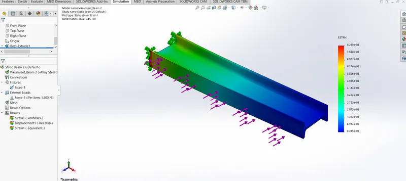
Strain1 |
ESTRN: Equivalent Strain |
8.245e-09 Element: 5759 |
8.288e-05 Element: 1397 |
STUDY 3: Structural analysis of C Section Beam
Study name Static 1
Analysis type Static
Mesh type Solid Mesh
Thermal Effect: On
Thermal option Include temperature loads
Zero strain temperature 298 Kelvin
Include fluid pressure effects from SOLIDWORKS Flow Simulation Off
Solver type FFEPlus
Inplane Effect: Off
Soft Spring: Off
Inertial Relief: Off
Incompatible bonding options Automatic
Large displacement Off
Compute free body forces On
Friction Off
Use Adaptive Method: Off
Stress Plot
|
Name |
Type |
Min |
Max |
|
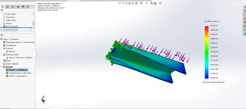
Stress1 |
VON: von Mises Stress |
5.806e+04 N/m^2 Node: 1721 |
3.820e+07 N/m^2 Node: 19240 |
Displacement Plot
|
Name |
Type |
Min |
Max |
|
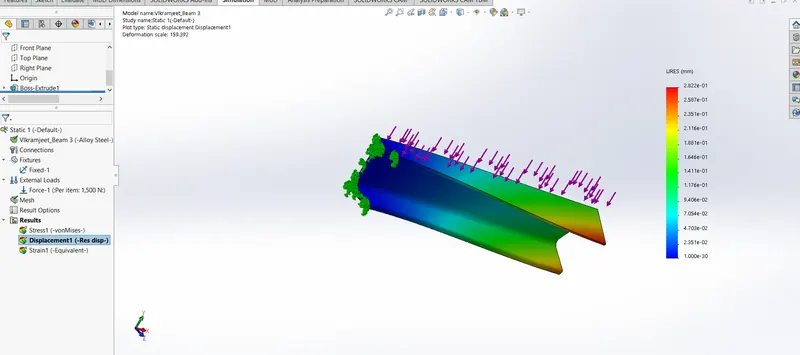
Displacement1 |
URES: Resultant Displacement |
0.000e+00 mm Node: 1 |
2.822e-01 mm Node: 66 |
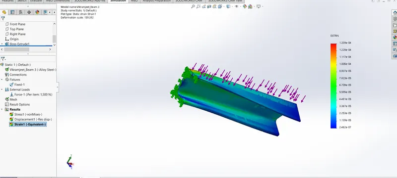
Strain Plot
|
Name |
Type |
Min |
Max |
|
Strain1 |
ESTRN: Equivalent Strain |
2.462e-07 Element: 1922 |
1.339e-04 Element: 1424 |
CONCLUSIONS:
• On comparison of the stress plots, maximum induced stress is least in case of the rectangular beam and largest in the case of C section beam. I section beam is observed to have an intermediate value of maximum stress.
• From the displacement plots, it is found that minimum displacement occurs in the rectangular beam and maximum displacement occurs in the C-section beam. I section beam experienced intermediate max displacement.
• From the strain plots, it is found that the maximum amount of strain is observed in C section beam and the minimum in rectangular beam. I section beam is observed to have an intermediate strain.
• Another important observation to be noted is that the C-section beam is subjected to torsion, which is undesirable in any beam application. Therefore, it is the least preferred among the three beams.
• The stress induced in both the I-section and rectangular beam is well below the yield strength of the material. Therefore both the beams will sustain the force of 1500N without failure, but in case of l-section beam, the distribution of stress is quite uniform when compared to rectangular beam. This type of stress distribution is usually preferable for higher operational life of the beam.
Considering all the above factors, I-section beam could be concluded as the best of the three beams.