Aston Martin ONE-77 Challenge-11 (Project)

OBJECTIVE
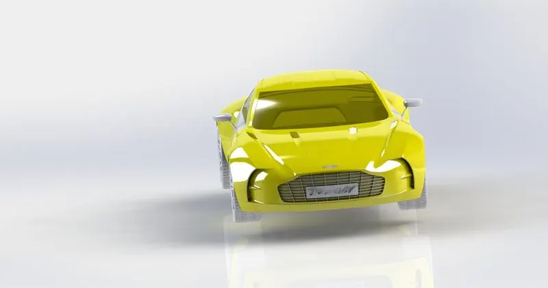
The objective of the project is surface model all the parts of an Aston Martin one-77 and assembling it to create the Photo-Realistic rendering,
INTRODUCTION
The Aston Martin One 77 is a two-door, two-seater flagship sports car built by the British car manufacturer Aston Martin. The Aston Martin One 77 is 4601 mm in length, 2204 mm wide including the wing mirrors and stands at an overall height of 1222 mm. The wheelbase of the car is 2791 mm and has a front track of 1706 mm and rear track is 1627 mm.
SolidWorks is a solid modelling computer-aided design (CAD) and computer-aided engineering (CAE) computer program published by Dassault Systèmes, that runs primarily on Microsoft Windows. SolidWorks is a solid modeller to create models and assemblies.
Rendering of the assembly is done to make good quality 2D images for the purpose of advertising and promotion of the products before selling it to the customers. Photorealistic rendering creates high quality images or motion graphics if available so as to look appealing in various environments and backdrops.
SOLIDWORKS Visualize is a photo-realistic rendering tool that utilizes our CAD data to create magazine quality images or commercial quality animations.
DESIGN APPROACH
MODELLING > ASSEMBLING > RENDERING
DESIGN METHODOLOGY
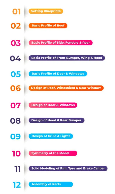
FEATURE COMMANDS
1.Extruded Boss/Base: The Extruded Boss is the most basic of all SOLIDWORKS features and extrudes a sketch along a straight-line path
to add material. As a sketched feature, it requires a sketch before use. Once the sketch has been created, exit the sketch and select the Features tab of the Command Manager. Then, click the Extruded Boss/Base command. If a yellow dialog box appears in the Property Manager asking you to create a new sketch, don't worry-simply click on the sketch in the graphics area to use it for the feature. The
Property Manager for the Extruded Boss allows you to control starting location, extrude depth and draft for the feature, among several other parameters.
2. Extruded Cut Similar to the extrude boss feature this feature needs a sketch on the solid body which needs to be cut and the
desired shape is then cut off.
3. Split Lines are used to divide model faces into two. Split lines are created like any other sketched feature. They can be one or more connected sketch entities. They must be oriented so that they will pass through model faces when projected normal to the sketch plane.
4. Dome It can add one or more domes to the selected planar or non-planar faces. The software calculates the distance using the radius of the arc as basis for the dome
5. Pierce Relationships: The pierce relationship is used in sweeps. It can be thought of as a 3D coincident relationship. In our spring, the
circle will follow the helix. Think of the helix as a thin piece of wire and the profile sketch a being drawn on a piece of paper. If we stick
the wire through the paper at the center of the circle, this would be a pierce relationship. When we perform the sweep, the paper will
slide along the wire, held at the pierce point.
6. Project Curve : Select Bi- directional to create a projection that extends on both sides of the sketch. The curve can be used as a path for sweep
7.Composite Curve :We can create composite curves by combining curves, sketch geometry and model edges into a single curve. Composite curve can be used as a guide curve when creating a loft or a sweep
8. Wire Frame
It is a view mode in which all edges of the part or assembly are displayed.
SURFACE MODELLING
Surface Modelling is a method of creating planar or non-planar complex geometry which has zero thickness. This zero thickness geometry is known as surface. We can convert surface models into solid models. We can also extract a surface from solid model using the tools available for surface modelling
SURFACE COMMANDS
• Lofted Surface: Creates a lofted surface between two or more profiles or sketches. We should specify start and end constraints and add guide curves to control path shape.
Boundary Surface: This feature lets to create surfaces that can be tangent or curvature continuous in both directions.
• Revolved Surface: Revolves a selected sketch around an axis.
• Swept Surfaces: It sweeps a closed profile along an open or closed path to create surface feature.
• Filled Surface: Patches a surface within a boundary defined by edges, sketches or curves.
• Ruled Surfaces: Inserts a ruled surfaces in a specified direction from edges. Tangent to surface, Normal to Surface, Tapered to vector, perpendicular to vector or sweep can be selected.
Trim Surface: It trims the surface where a surface intersect with another surface, a plane or a sketch.
• Knit Surface: It combines two or more adjacent, non-intersecting surfaces into a single surface body. We can also create solid body.
• Move/ Copy Surfaces: Moves or copy surface about a plane or a sketch. .Offset surface: Helps to create an surface with gaps.
• Extend Surface: Extends one or more edges or faces on a surface based on end conditions and extension type
• Mirror Surfaces: It is a copy of a selected feature, mirrored about a plane or face. If the original sketch is changed, mirrored copy also this updated automatically.
•Reference Plane: We can create planes in part or assembly document.
• Fillet: It is an internal rounding of a comer or edge in a sketch
• Split Line: It divides selected face into multiple separate faces.
PART MODELLING DESCRIPTION
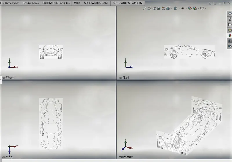
1.Blueprint Setup
A blueprint is a reproduction of engineering drawing using contact print process on light sensitive sheets. Blueprint is a guide for making something,
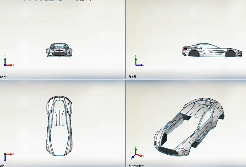
2.Body : Vehicle body is the outer covering typically made of metal fibre glass.plastic etc. It is designed considering aerodynamics for carrying passengers.Body design gives importance to safety rather than better outlook of vehicle.
TOOLS USED
Sketch Tools
• Spline
• Line
• Circle
• Offset Entities
Convert Entities
Surface Tools:
• Surface knit
• Surface Extend
• Offset Surface
• Move/ copy bod
Feature Tools:
Trim
Fillet
Extrude Cut
. Combine
Extrude Boss/Base
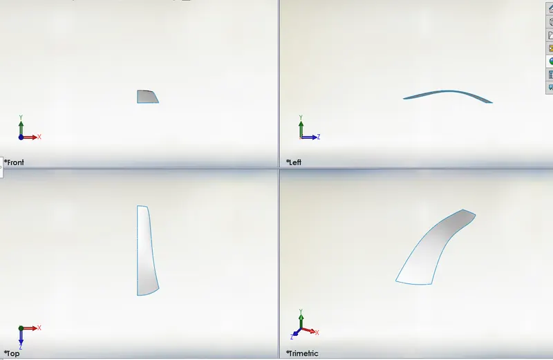
3.Roof
An automobile roof or car top is the portion of an automobile that sits above the passenger compartment, protecting the vehicle occupants from sun, wind, rain, and other external elements.
Tools used
Sketch Tools:
Line
Spline
Surface Tools:
Boundary Surface
Surface trim
Feature Tools:
• Projected Curve
• Mirror
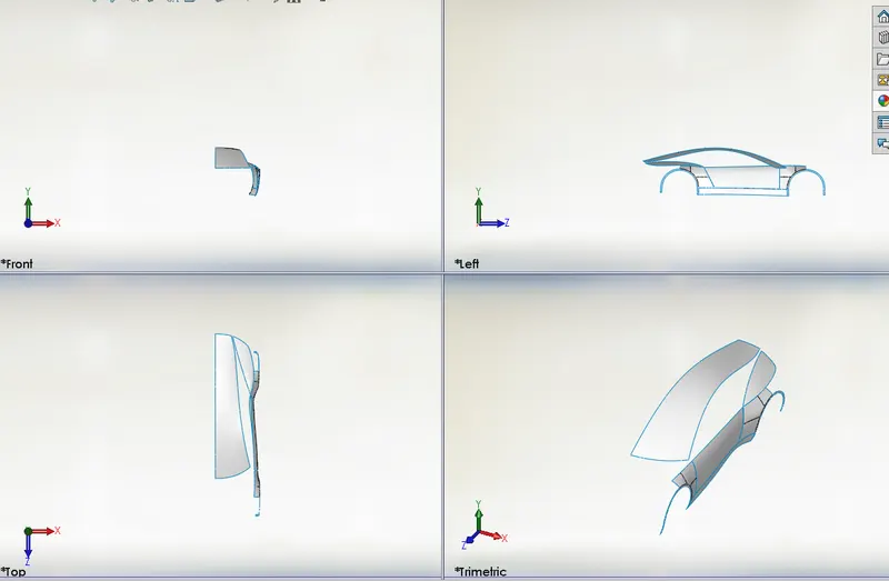
4. Side and Fenders
A fender is an automobile part that is bound to the vehicle frame and is placed as cover on the upper side of the tyres. Its primary purpose is to prevent sand, mud and other road spray from being thrown into the air by rotating tyre. This part is also known as mud guard.
TOOLS USED
Sketch Tools:
• Spline
Line
Circle
Offset Entities
Convert Entities
Surface Tools:
Surface Trim
• Surface Extrude
• Boundary Surface
• Surface Fill
Surface knit
Feature Tools:
• Projected Curve
• Reference Plane
Trim
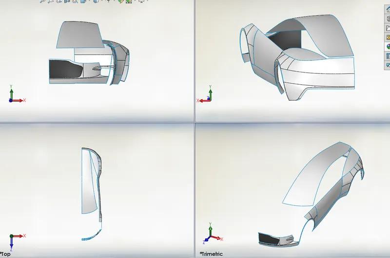
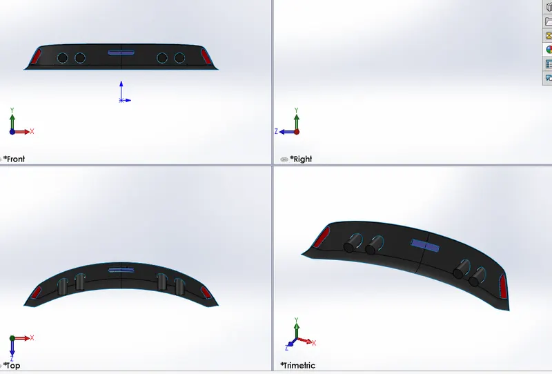
5. Rear and Front Bumper
A bumper is a structure attached to or integrated with the front and rear ends of a motor vehicle, to absorb impact in a minor collision, ideally minimizing repair costs.Stiff metal bumpers appeared on automobiles as early as 1904 that had a mainly ornamental function. Numerous developments, improvements in materials and technologies, as well as greater focus on functionality for protecting vehicle components and improving safety have changed bumpers over the years. Bumpers ideally minimize height mismatches between vehicles.
TOOLS USED
Sketch Tools:
Spline
• Line
. Circle
Offset Entities
Convert Entities
3D sketch
Surface Tools:
• Surface Trim
• Surface Extrude
• Boundary Surface
• Surface Fill
• Surface knit
• Ruled Surface
• Offset Surface
• Surface Extend
Feature Tools:
• Projected Curve
• Reference Plane
• Trim
• Extrude Boss
• Extrude Cut
Move/Copy
Mirror
• Appearance
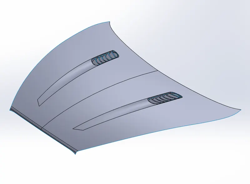
6.Hood
The hood or bonnet is the hinged cover over the engine of motor vehicle.Hoods can open to allow access to the engine compartment, or trunk for maintenance and repair.
TOOLS USED
Sketch Tools:
• Spline
. Line
Offset Entities
• Convert Entities
3D sketch
Surface Tools:
Surface Trim
Surface Extrude
• Boundary Surface
• Surface knit
• Offset Surface
• Move/copy body
• Cut with Surface
Feature Tools:
Projected Curve
Reference Plane
• Trim
• Split
Fillet
. Linear Pattern
Extrude Cut
Combine
• Mirror
7.Windows and Windshields
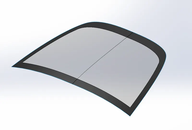
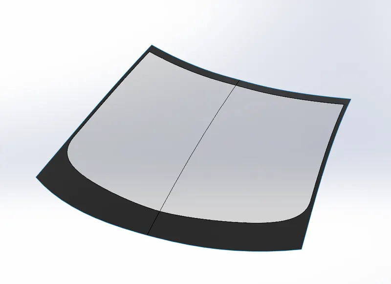
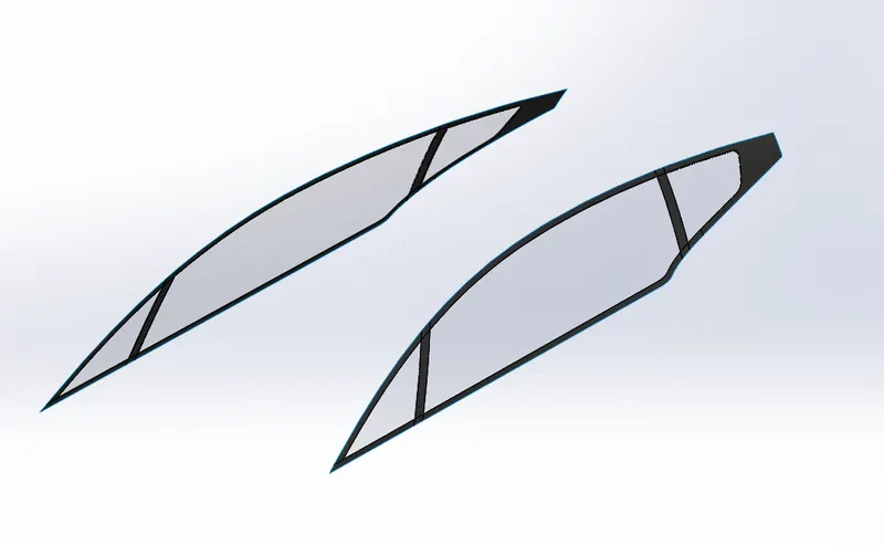
The windshield or windscreen is the front window, which provides visibility while protecting occupants from the elements. Modern windshields are generally made of laminated safety glass, a type of treated glass, which consists of, typically, two curved sheets of glass with a plastic layer laminated between them for safety, and bonded into the window frame. Windshields protect the vehicle's occupants from wind and flying debris such as dust, insects, and rocks, and provide an aerodynamically formed window towards the front UV coating may be applied to screen out harmful ultraviolet radiation
TOOLS USED
Sketch Tools:
Spline
• Line
• Offset Entities
• Convert Entities
3D sketch
Surface Tools:
• Surface Trim
• Surface Extrude
• Boundary Surface
Surface Fill
Surface knit
• Offset Surface
• Cut with Surface
Feature Tools:
• Projected Curve
• Trim
Split
Fillet
Extrude Cut
Mirror
8.Doors
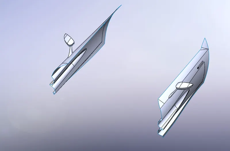
A car door is a type of door opening, typically hinged on its front edge, but sometimes attached by other mechanisms such as tracks, for entering and exiting a vehicle. Doors most often integrate side windows for visibility from inside the car and can be locked to secure the vehicle. Car doors may be manually operated or with power assist supplied by the vehicle.
TOOLS USED
Sketch Tools:
• Spline
. Line
Offset Entities
• Convert Entities
3D sketch
Surface Tools:
Surface Trim
Surface Extrude
• Boundary Surface
• Surface Fill
• Surface knit
• Offset Surface
• Surface Extend
• Move/copy body
• Cut with Surface
Feature Tools:
Projected Curve
Reference Plane
• Trim
• Split
Fillet
. Linear Pattern
Extrude Cut
Combine
• Mirror
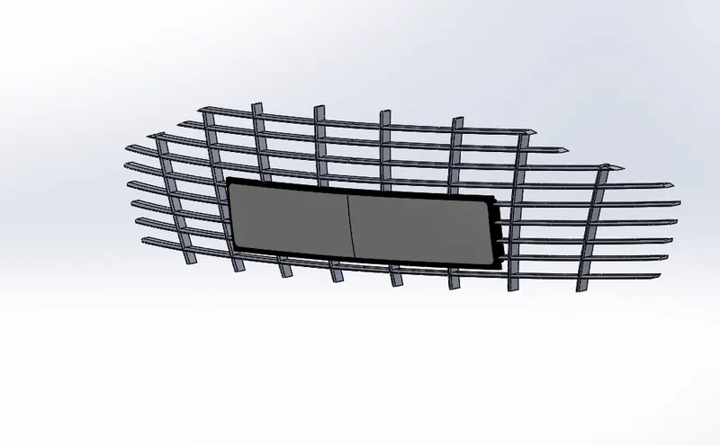
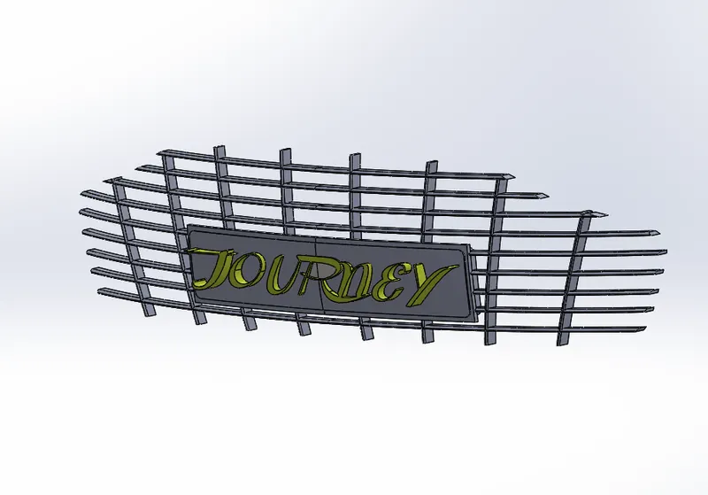
9.Grille
A grille covers an opening in the body of a vehicle to allow air to enter or exit.Most vehicles feature a grille at the front of the vehicle to protect the radiator and engine Merriam-Webster describes grilles as "a grating forming a barrier or screen; especially: an omamental one at the front end of an automobile. Other common grille locations include below the front bumper, in front of the wheels (to cool the brakes), in the cowl for cabin ventilation, or on the rear deck lid (in rear engine vehicles).
TOOLS USED
Sketch Tools
• Spline
Line
• Offset Entities
Convert Entities
Surface Tools:
Surface knit
Surface Extend
• Offset Surface
• Move/ copy bod
Feature Tools:
Trim
Fillet
• Extrude Cut
Combine • Extrude Boss/Base
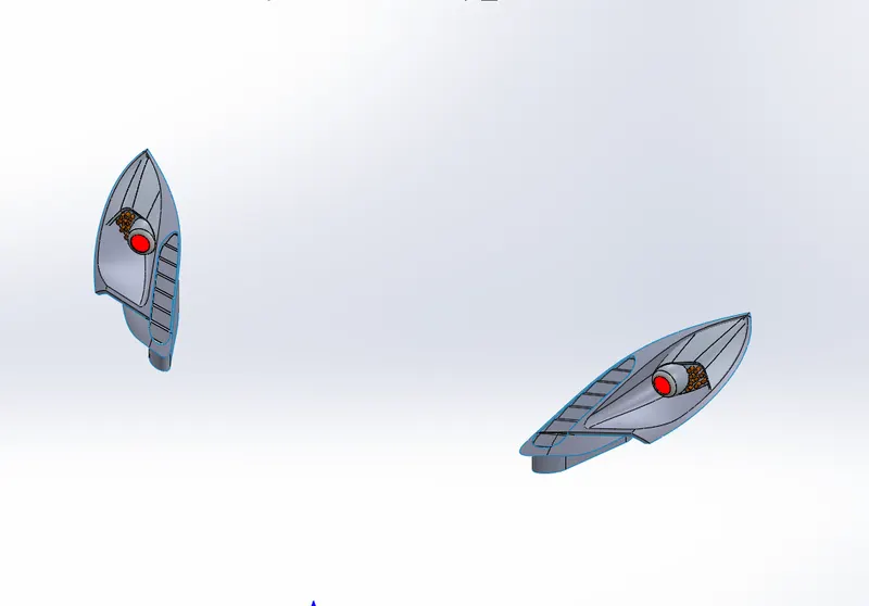
10.Lights
A headlamp is a lamp attached to the front of a vehicle to illuminate the road ahead Headlamps are also often called headlights, but in the most precise usage, headlamp is the term for the device itself and headlight is the term for the beam of light produced and distributed by the device. The lighting system of a motor vehicle consists of lighting and signalling devices mounted or integrated at the front, rear, sides, and in some cases the top of a motor vehicle.hese light the roadway ahead for the driver and increase the visibility of the vehicle, allowing other drivers and pedestrians to see a vehicle's presence, position, size, direction of travel, and the driver's intentions regarding direction and speed of travel.
TOOLS USED
Sketch Tools:
. Spline
• Line
• Circle
• Offset Entities
• Convert Entities
• 3D sketch
Surface Tools:
• Surface Trim
• Surface Extrude
• Boundary Surface
• Surface Fill
• Surface knit
• Ruled Surface
• Offset Surface
• Surface Extend
• Move/copy body
• Cut with Surface
• Thicken
Feature Tools:
Projected Curve
Reference Plane
• Trim
• Split
• Fillet
• Linear Pattern
Extrude Cut
. Combine
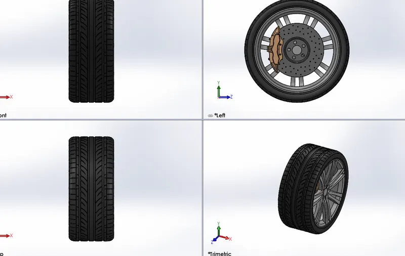
11.Front and Rear Wheel
Wheel consists of rim.tyre and brake which make it the component that makes the connection between the car and the ground. The rim is an important strength component which ensures safe load carrying capacity of the car.it should have enough compressive strength and able to absorb shocks and impacts. The tyres are the main contact surface to the ground. The wheel also houses a disc brake rotor and its caliper. The designing of front and rearTo begin a revolved part is created on the right plane which is the rim now the spokes are sketched on the right plane and extruded wheels are similar the differences is in the size of the wheels.
Front Wheel
Rear Wheel
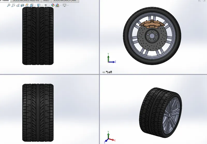
Tools Used
Sketch Tools:
• 3 point arc
• spline
• Circle
• Trim
• Rectangle
• Fillet
Feature Tools:
• Revolve
• Extruded Boss/base
• Circular pattern
• Chamfer
Appearance
• Revolve Cut
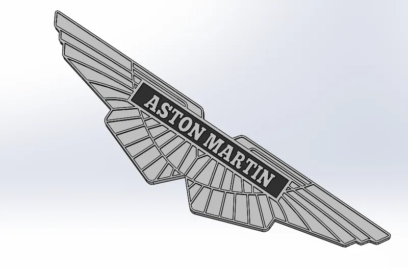
12.Emblem
This part was entirely made using solid modelling Extrude boss, extrude cut, mirror, combine etc are used.
ASSEMBLY
Approach: Bottom-Up Bottom-Up design is the traditional method. You will first design and model the part individually, then insert them into an assembly and use mates to position parts. To change parts you must edit them individually. These changes are then seen in assembly. If there is any interference in the assembly or changes required in the assembly you need to modify the components individually either in the assembly level or in the part document level
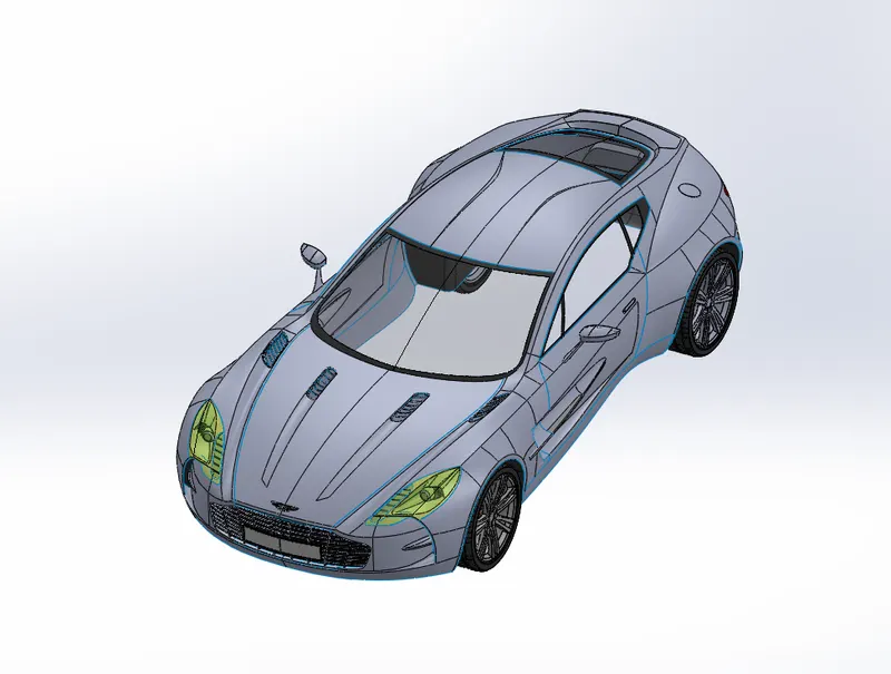
After making all the parts the most important part of assembling the entire car to a single file begins. To start with bringing the body first and using its plane and geometry as a base for the entire solid assembly, the second part we bring in is the doors. The planes of doors made coincident mate with the curresponding planes of body.After that we bring hood, windows, front and rear windshields, grille and rear bumper made coincident mates with the planes of body. For front and rear wheel, we use distance mates of 93,3 mm for front wheel and 92.2 mm for back wheels from the front plane.Finally the Aston Martin emblem fixed with the body.
PHOTOREALISTIC RENDERING
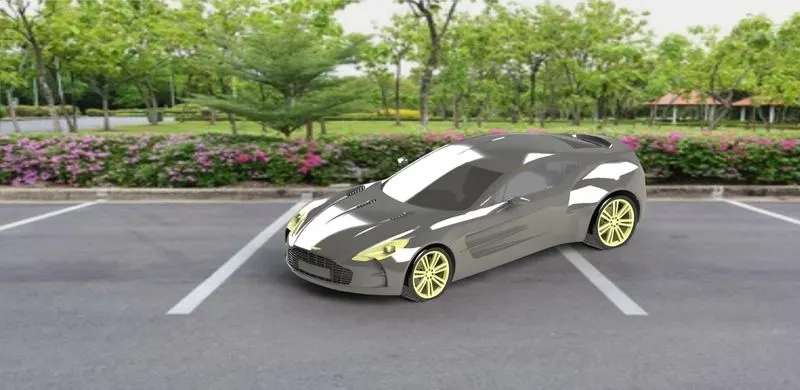
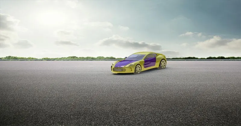
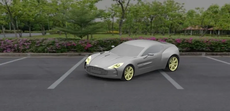
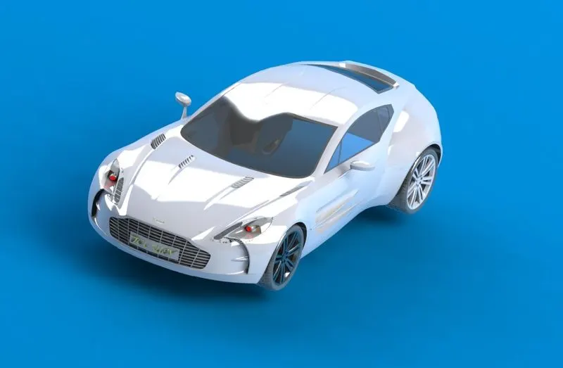
Rendering of the assembly is done to make good quality 20 images for the purpose of advertising and promotion of the products before selling it to the customers, Photorealistic rendering creates high quality images or motion graphics if available so as to look appealing in various environments and backdrops. We try to make it more realistic by giving it a camera view setting the desired lights and the focal distance creating the angle of the view and saving the camera angle which gave a realistic view to the car. Now we take our assembly file into solid works visualize where we start making the product more and more realistic with adding the background changing the and adjusting the brightness, shadow density and gamma levels according to the different requirements of the different backgrounds changing the color of the model and checking what suits the best with which background until we get the desired and astonishing product ready.
Isometric View:
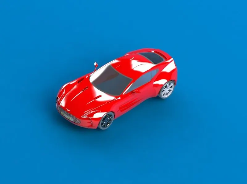
CONCLUSION : In the course of this project we have to modelled the entire Aston Martin One - 77 and learn new tool and techniques .