Project 1
TABLE FAN OUTER CASING
AIM- In this assignment we have to Create a mold of table fan outer casing.
MOLD DESIGN- Mold design is a decisive factor for the molding success such as dimensioning and location of the sprue gates, dimensioning of shear edges, flow aids, cooling and ejector techniques, etc.
PLASTIC MOLD DESIGN- Each injection mold design must have a gate, or an opening that allows the molten plastic to be injected into the cavity of the mold. Gate type, design, and location can have effects on the part such as part packing, gate removal or vestige, cosmetic appearance of the part, and part dimensions and warping.
The process involves the injection of melted plastic into a mold, which is made of steel. The mold itself has cavities that will form the parts; once injected, the molten plastic fills the cavities and the rest of the mold. Once cooled, the parts are ejected by pins.
The injection moulding process involves heating & injecting plastic material under pressure into a closed metal mould tool. The molten plastic cools & hardens into the shape inside the mould tool, which then opens to allow the moulding to be ejected or removed for inspection, delivery or secondary operations. Injection moulding is a manufacturing process that allows for parts to be produced in large volumes. It works by injecting molten materials into a mould (or 'mold' in the United States). It is typically used as a mass production process to manufacture thousands of identical items.
FEATURED USED IN THIS PROJECT
TOOLING DIRECTION- The direction in which the mold blocks move the cavity or the direction in which the component eject from the mold is called tooling direction.
The selection of tooling direction always be minimum number of undercuts is formed and the overall difficulty of the mold reduces.
DRAFT ANALYSIS-Draft Analysis is located under Mold Tools > Draft Analysis in the Command Manager. If the Mold Tools tab is not visible, simply right-click on any of the existing tabs and select Mold Tools from the flyout menu to enable it.
With Draft Analysis activated, all we need to do is select a direction of pull and specify the minimum draft angle needed for a clean release from the mold. First, select a face to use as a reference. The part will be pulled perpendicular to this face, and we can change the direction by toggling the arrow to the left of the face selection under Analysis Parameters.
After selecting the face and direction of pull, specify the required angle. The default is 3 degrees, but we can change this to anything we want. Faces will be highlighted in the graphics area.
SCALE- Scales the models by a specifies factor, you can scale a part or surface, model about its centroid, the model origin, or a coordinate system. scales only the geometry of the model does not scale dimensions, sketches or reference geometry. Parts can sometimes shrink as part of the manufacturing process. The Scale tool in SOLIDWORKS lets us scale the part up or down as needed, which is particularly helpful for when parts shrink with molding or 3D printing. To open the Scale tool, select the Mold Tools tab and then Scale in the Command Manager.
PARTING LINES- The parting line is where the two halves of the mold meet around the parameter of the part. All parting lines need to seal properly when the mold is clamped in a molding machine. The form of parting line depends on the specific situation of the plastic part, but generally there are several types: vertical stepped, inclined, curved and integrated parting lines.
SHUT- OFF SURFACES- Creates mold shut-off surfaces by creating a surface patch along a parting line or edges that formed a continuous loop. these prevent any through holes in the cavity or core surfaces bodies.
To cut a tooling block into two pieces, you need two complete surfaces (a core surface and a cavity surface) without any through holes. Shut-off surfaces close up the through holes. You create shut-off surfaces after you create the parting lines.
PARTING SURFACES- A parting surface is a surface that separates the mold block into two parts – the core and the cavity.
Create a parting surface that extrudes from parting lines or edges split the model cavity from the core. You can also adjust parting surface manually.
EXTRUDED BOSS- After the surface are created, sketch is drawn to create solid core and cavity blocks using extruded boss command.
CUT WITH SURFACE-This command is used to cut the solid block with the surface that we created the shape of the core and cavity block. Assign green color to cavity block and red color for core block.
SPLIT- Split command is used to split the mold block. created a sketch and a plane and perform the split option then selected the part that need to be split. slider is created using split command insert the created slider into new part in assembly.
Move face-It is available in mold tool tab used to move face of a solid body.
Move/copy bodies- It is available in mold tool used to move copy and rotates solid body or surface bodies.
Delete/keep bodies- it is used to delete the unwanted body from the solid body. Or keep it.
COMBINE- combine option is used to subtract the slider from the main body, by doing this we get the shape of the slider.
HOLE-WIZARD- After the washers are created, a hole must be provided on the core block for proper alignment of the bolts with the core block.to create the hole wizard is helpful to create the required holes on the core block.
Metric M6 hole is selected from the hole wizard.
CORE- core command is used to create the ejector pin on the core mold block. for 6mm pin give the clearance is 6.95mm.
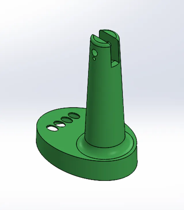
Given table fan outer casing
Draft analysis- Draft analysis examines the faces of the model for sufficient draft to ensures that the part eject properly from the tooling. By using draft analysis, we check whether adequate draft is given or not. Draft analysis was given 0.5 degree and checked if there are any feature that required draft.
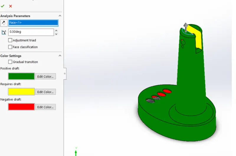
We notice that there was draft required for this model that is why we given 1 degree draft.
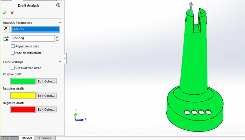
SCALING- increase the size of the part by using the scale command in solid works. Because of avoid shrinkage of the part when manufacture.
Assume the plastic is ABS and its shrinkage value is 0.6%
0.6/100+1=1.006
PARTING LINE- use parting line command to create parting line to separation of core and cavity.
First select the parting line command in the command manager select any flat face of the component for tooling axis and give the value and click draft analysis it forms the parting line in the model, most of cases the software selection was right but sometime it is not correct those cases we need to select the proper parting line.
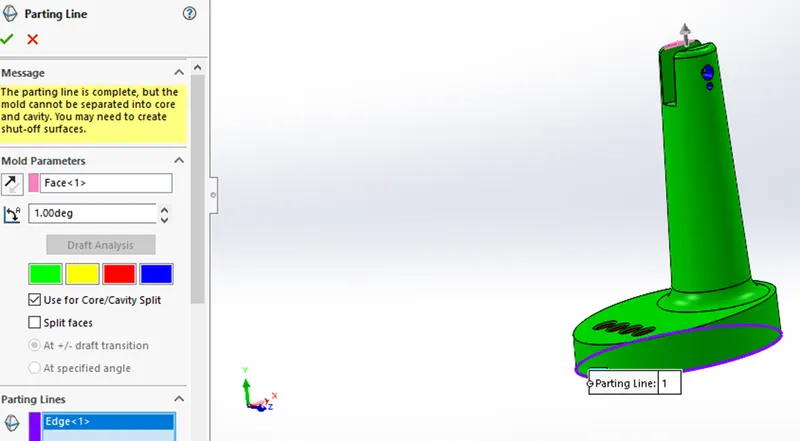
SHUT-OFF SURFACE- we use shut off surfaces for close the holes and separate the mold into core and cavity. Shut off surface should be created where the core and cavity meet each other.
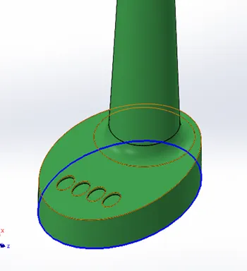
PARTING SURFACE-The parting surface is made along the parting line to separate the core from the cavity.
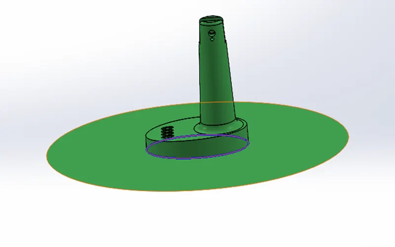
CORE&CAVITY SURFACE- Go to direct editing option move/copy bodies tool copy of parting surface and knit with core and cavity surface.
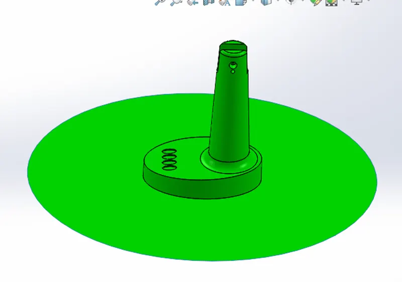
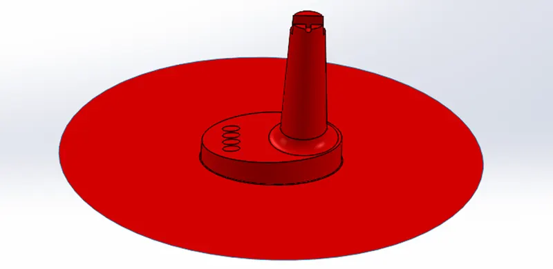
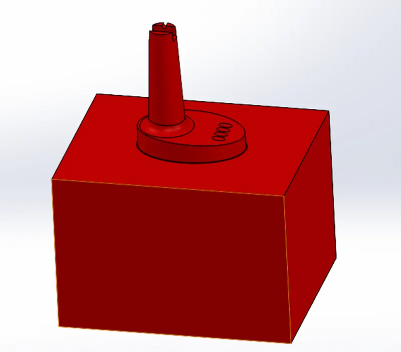
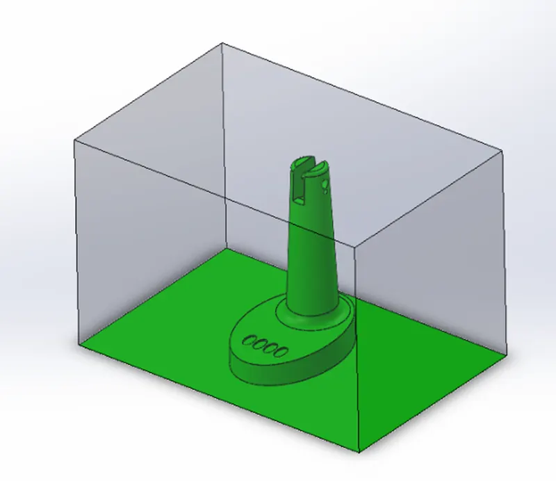
CORE&CAVITY BLOCK- create an assembly create new part one is core and another is cavity. create a cuboid on both core and cavity surfaces. Then extruded it both directions, cut the core and cavity surface to make core and cavity block. Assign the color of the block for cavity block give green color and for core block give red color. And change the name in the feature tree to core and cavity block.
EJECTOR PIN- creating ejector pin in the core block. Ejector pin created near the ribs, for flat surface we create flat surface pin and for curved surface angled ejector pin. first create sketch on the flat face. create circle for the ejector pin 6mm diameter circle near the rib. Minimum distance 1mm between ribs and ejector pins. Make another circle diameter of 8mm concentric with the 6mm circle and make 8mm circle as construction.
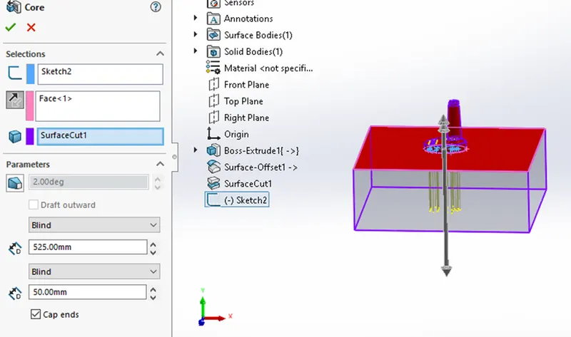
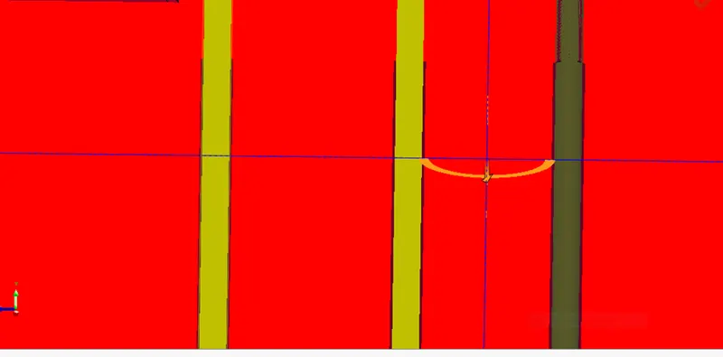
RELIEF- create relief for the ejector pin. For 6mm diameter circle relief is provided after 12mm distance. Create concentric circle around the circle.6.95mm diameter for standard relief. Use extruded cut option from offset 12mm sketch plane and then make extruded cut through all.
SLIDER- undercut are those feature in an injection molded part that prevent its ejection from the mold.
In the table fan casing model, there are two holes that from undercut. This prevents the removal of the part from the mold towards the direction of tooling to prevent this we create sliders. Sliders are separate blocks. Created which can be slide out the mold before the part is removed thus preventing the obstruction by the undercuts.
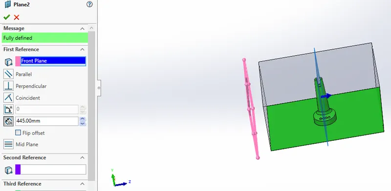
Sliders are created using split command by making the sketch as the profile of the undercut and the plane up to where it has to split.
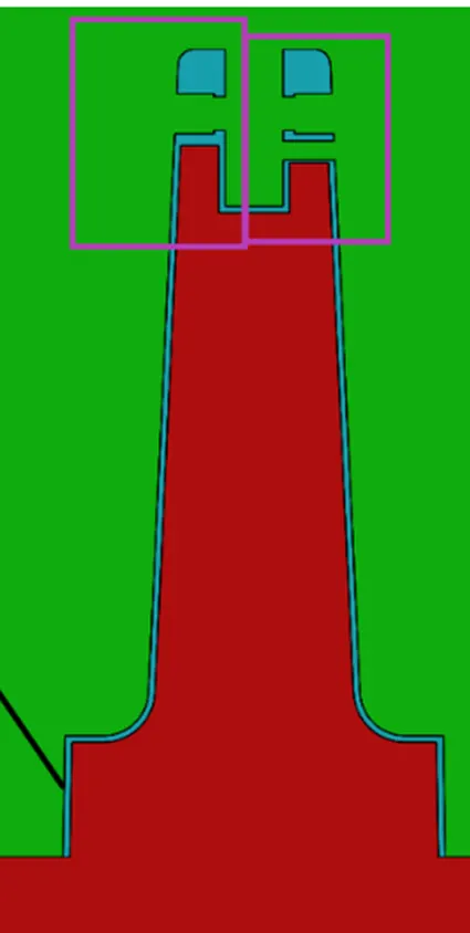
We will create a plane reference of front plane. We will create a sketch on the plane create a circle and extruded it.
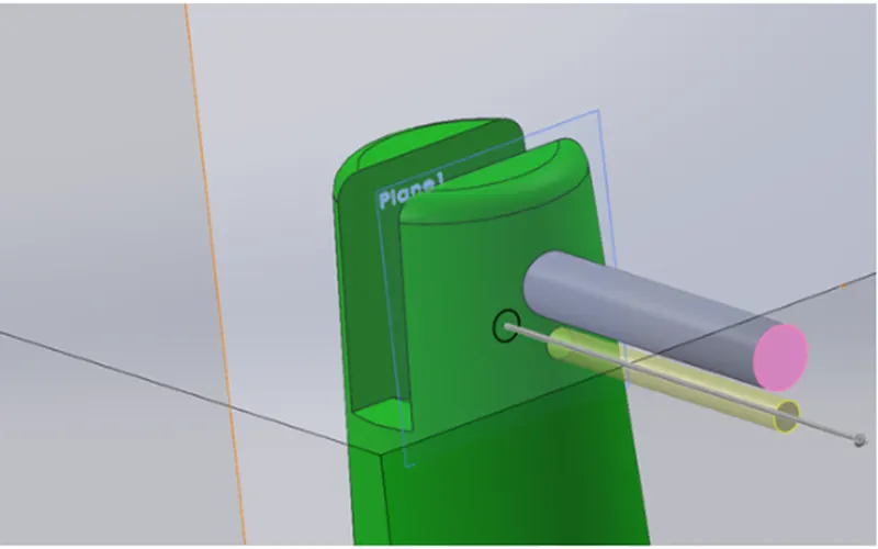
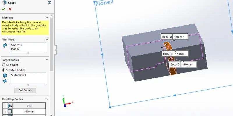
Create a sketch on the side face and using cut extruded cut the slider.
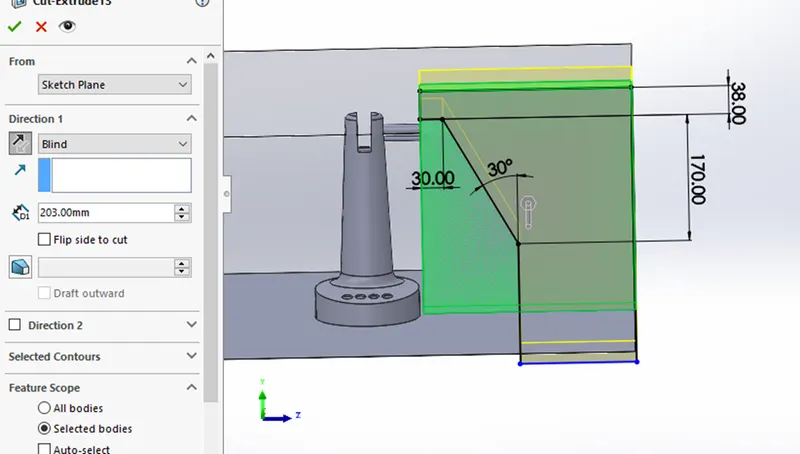
Then we will create a sketch extruded it and merge it with the block.
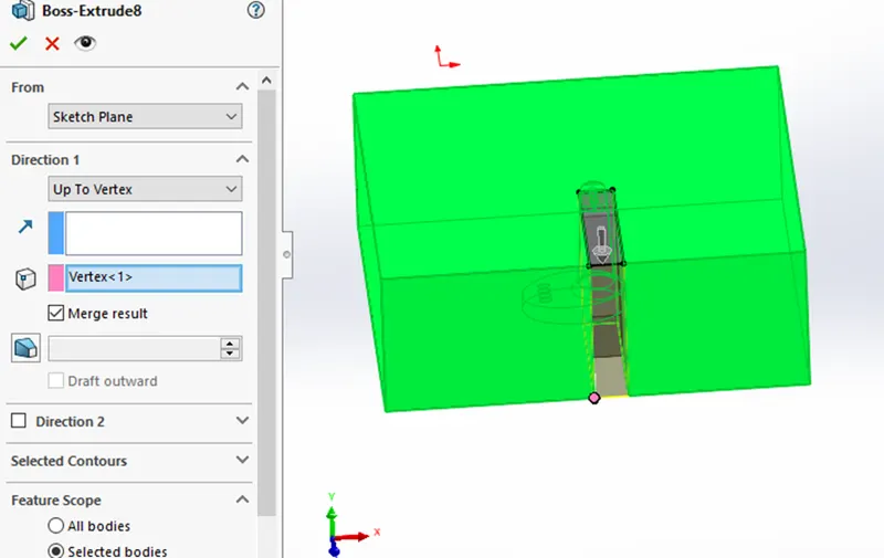
We create guideways in the slider. we will create a sketch and then extruded it up to vertex and merge with body.
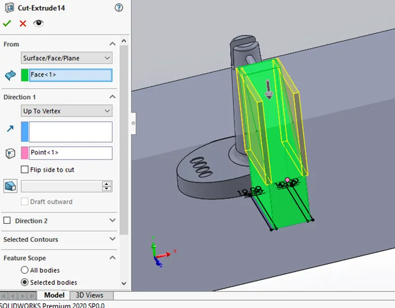
Then mirror the slider and pin body other side, we will use combine tool to combine the pin and slider body.
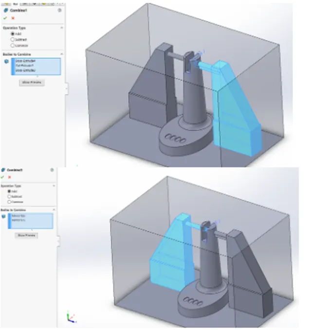
We will save these two sliders as Parasolid file and use combine tool and then subtract two slider body from cavity.
Then we will give fillet for this slider part.
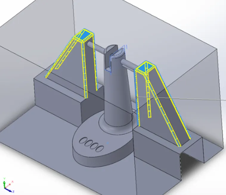
These sliders are modified such that washer and locking mechanism will be correctly designed.
The core and cavity block are made according to the shape of the slider after creating all mechanism using combine command.
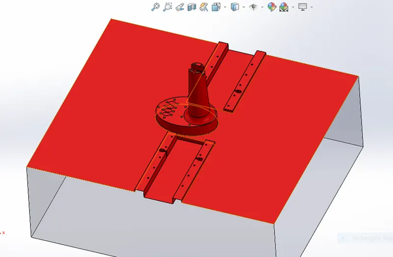
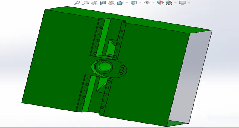
After that add separate part file in assembly named as washer, create a sketch for the washer and extruded option used to make washer. Due to add of washer there will be an intersection in core and cavity block we should remove the intersection material.
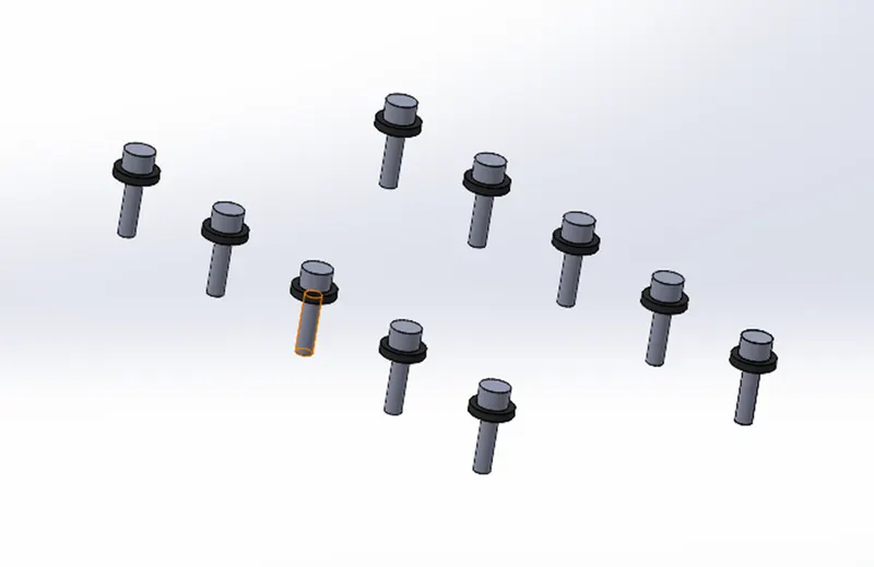
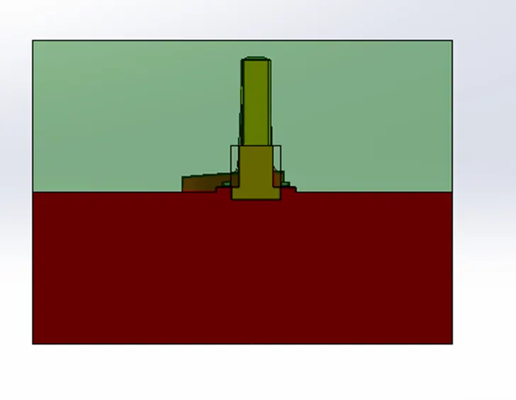
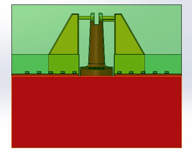
LOCKING MECHANISM- As the slider movement should redistrict, we should create a locking mechanism such that only some distance slider can move for this certain space should be allocated in cavity block that spaced is designed considering the distance for travel of slider.
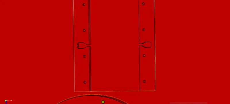
SOME MOLD DESIGN IMAGE
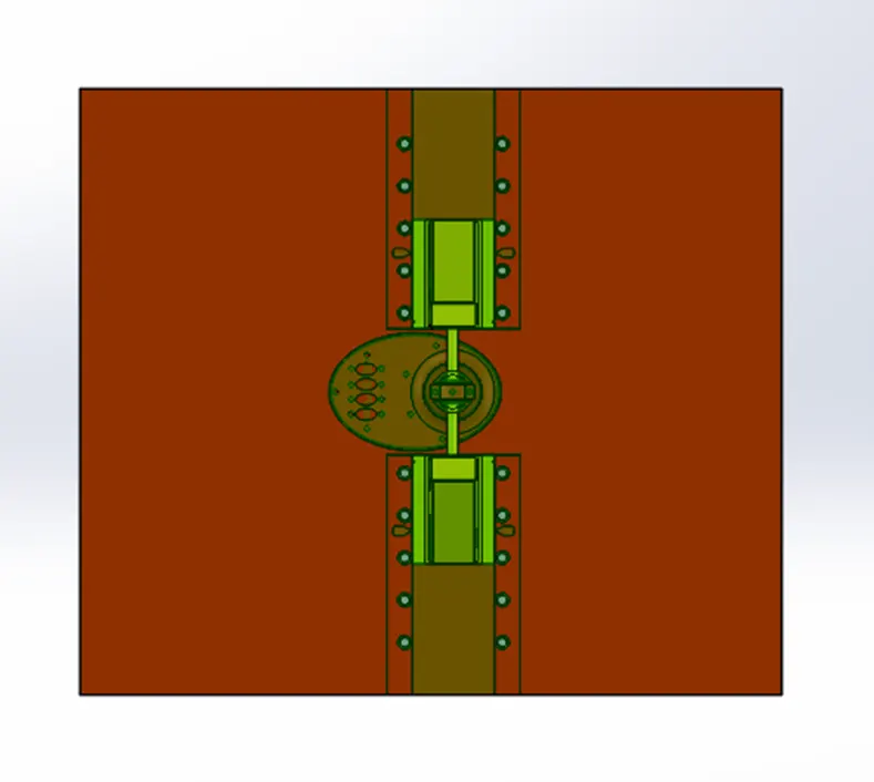
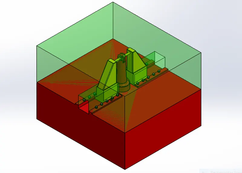
CONCLUSION-We have successfully created the core cavity slider and washer for the table fan outer casing model.