Project 1
In this project 3 converters are been designed as per given in the project table they are as follows :-
|
Project No:- |
Converter Type |
Input Voltage |
Output voltage |
Power level |
|
1 |
Buck CCM |
400-500V |
300V |
5Kw |
|
2 |
Cuk Converter |
30-60V |
-45V |
300w |
|
3 |
Boost CCM |
20-30V |
40V |
600w |
Project 1.1:-
Schematic of DC-DC Buck Converter :-
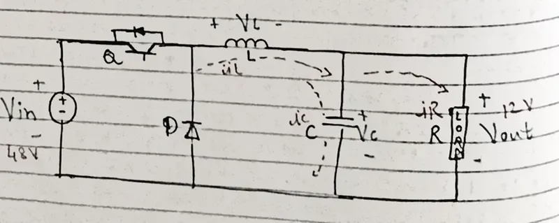
First , we will use the voltage ratio equ. To calculate the needed duty cycle:-
Vout/Vin=300/400
D=0.75
We know that the output voltage is 300v and we require 5Kw as output power
Therefore ,
P=5kw
P=5000W
We can also determine that,
R=Vout^2/P
R=300^2/5000
R=18 Ohm
Now, we will design the converter inductor:
We know that
`Il=Io=P/Vo=5000/300=16.6667A`
Then , let us design for 10% ripple in the inductor.
Then
`∆iL=0.1*16.667A=1.667A`
We know that ,
`L=(Vout/(fs*∆Il))(1-D)`
`L=(300/(20k*1.667A))=0.25=0.224mH`
Then l=0.224mH
Let us now design the output capacitor for 5% ripple :-
`Cout=((1-D))/(8*L*fs^2*(∆Vo/Vo))``Cout=(1-0.75)/(8*0.24mH*20k^2*(0.05))=6.25 uF`
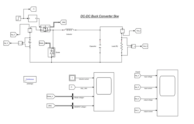
We have found out the duty cycle , value of resistor , capacitor and inductor the next step we will design the model in Simulink .
The model is as shown below –
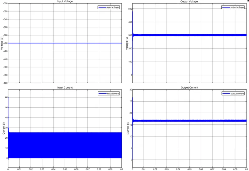
Scope for input and output voltage and input and output current :-
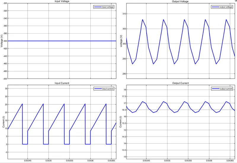
Zoomed in scope:-
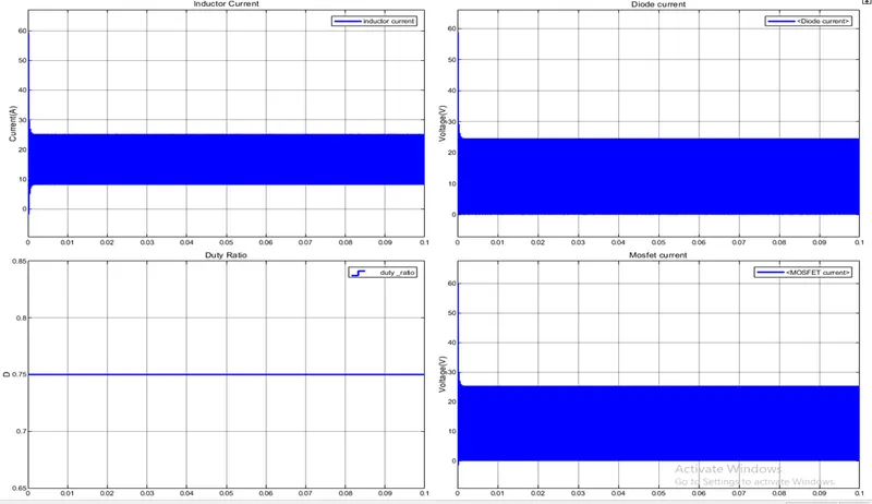
Scope of inductor current duty ratio , diode and mosfet current :-
Zoomed in scope
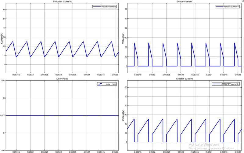
Here the output is as desired and the ripple of inductor current is 10% and of capacitor is 5%. We can see that the diode and mosfet gets tuned on and off one after another.
Cuk Converter :-
Given :-
Vin:- 30V-60V
Vout:- -45V
P:- 1KW
Fs:- 20KHz
First we will use the voltage ratio Equ. to calculate the needed duty cycle :-
`(-Vout)/Vin=(-45V)/60V=(-D)/((1-D))`
`(-45V)/60V=(-D)/((1-D))``D=0.4285`
Now we will design the Cuk converter inductor;
We know that ,
`Il1=Ii=P/vin=1000/60=16.667A`
`Il2=Io=P/Vo=1000/45=22.222A`
And
`R=〖Vout〗^2/P`
`R=45^2/1000=2.025 Ohm`
Let us design for the 10% ripple in the inductor:-
`∆iL1=16.6667*0.1=1.667A`
`∆iL2=22.222*0.1=2.222A`
We know that,
`L1=(Vin/Fs∆IL)D`
`L1=(60/(20K*1.6667))0.4285`
`L1>0.712 mH`
`L2=(60/(20K*2.222))0.4285`
`L2>0.5785 mH`
Thus we choose,
L1 =0.8 mH
L2=0.6 mH
Let us start designing the intermediate capacitor C1:-
`C1=VoD/Rfs∆Vc1`
`Vc1=vin-vo=60-(-45)=105V`
Thus ,
`∆Vc1=0.1*105=10.5v`
Let us now design the output capacitor Cout using Equ:-
`Cout=((1-D))/(8*L*fs^2*(∆Vo/Vo))`
`Cout=0.5715/(8*0.6mH*20k^2*(0.01))=60.297 uF`
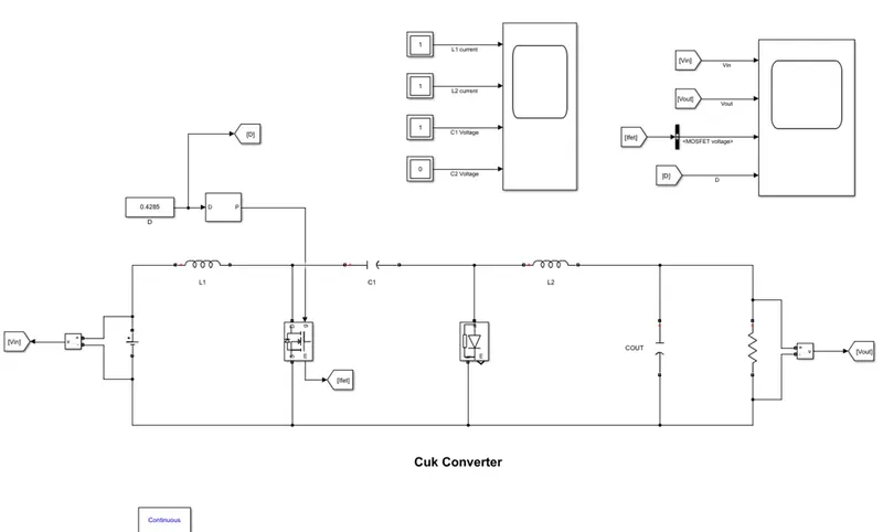
The MATLAB model is as shown below:-
The values calculated for the duty cycle , inductor , capacitor and resistor are set in the MATLAB model
Scope results zoomed out :-
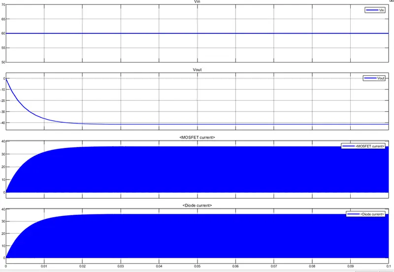
The above scope shows the input voltage , output voltage , mosfet and diode current:-
The zoomed in scope for the same is as shown below :-
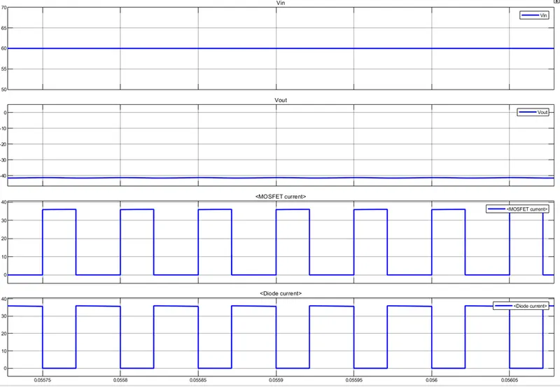
We can see from the scope that cuk converter as converted the Vin to the desired Vout and the output voltage is negative, though the output voltage has not achieved -45 V but its near to -42V , this is due to the resistances present in the circuit modelling.
Boost CCM:-
Given :-
Vin:- 20-30V
Vout:- 40V
P:- 600W
Fs:- 20KHz
Schematic of DC-DC Boost converter :-
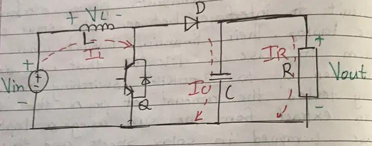
First we will use the voltage ratio Equ. to calculate the needed duty cycle :-
`Vout/Vin=40V/30V=1/((1-D))`
`D=0.25`
Now we will design the converter inductor;
We know that ,
`Il=Vin/((1-D)^2 R)`
And
`R=〖Vout〗^2/P`
`R=40^2/600=2.667 Ohm`
Thus,
`Il=Vin/((1-D)^2 R)`
`Il=30/((1-0.25)^2*2.667)`
`Il=30/1.5=20A`
Let us design for the 10% ripple in the inductor:-
`∆iL=0.1*20A`
`∆iL=2A`
We know that,
`L=(Vin/Fs∆IL)D`
`L=(30/(20K*2))0.25`
`L=0.1875uH`
Thus we choose,
L =0.2uH
Let us now design the output capacitor C using Equ:-
`Cout=D/Rfs(∆Vo/Vo)`
`Cout=0.25/(2.667*20k*0.1)`
`Cout=0.00004678 F`
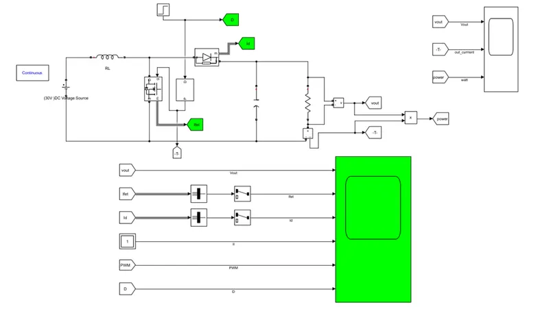
The MATLAB model is as shown below:-
The values calculated for the duty cycle , inductor , capacitor and resistor are set in the MATLAB model
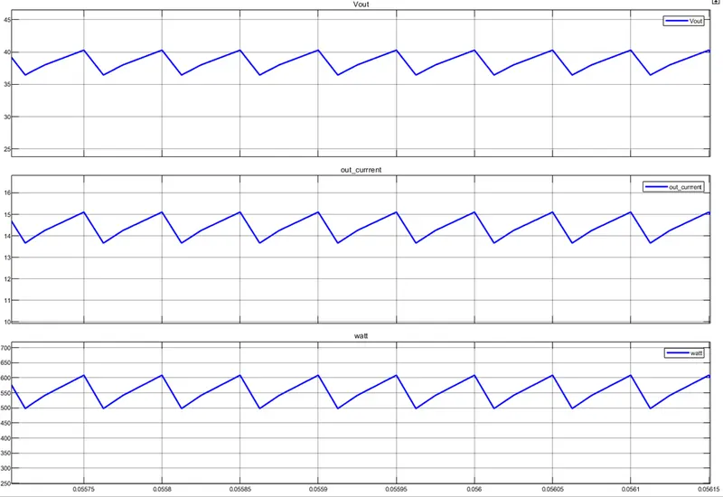
Scoped result for Vout ,Iout and power output :-
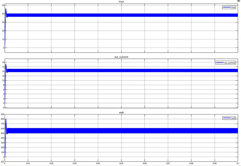
Zoomed in scope :-
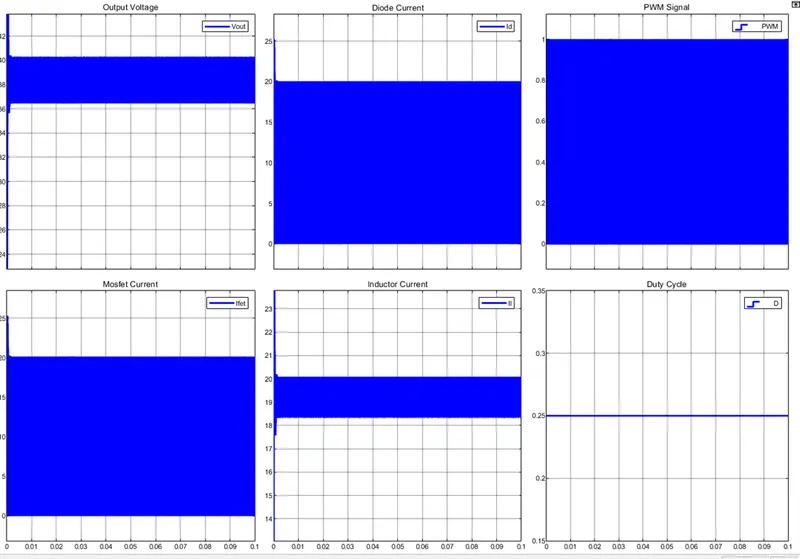
Scope for Vout, mosfet current, diode current , inductor current PWM Signal and Duty cycle :-
Zoomed In scope :-
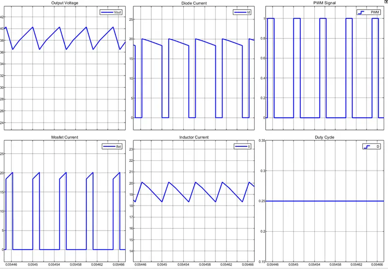
The converter is able to track the desired output as per the required design , we can see that when the mosfet is on and that time the diode is off and vise-vers , we can see that the converter is operating in CCM mode.