Project 1 - 2D meshing on the instrumental Panel
Objective:
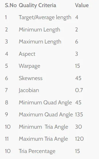
To Perform the geometric topology and to extract the midsurface to generate 2D Meshing for the given Instrument panel model according to the given element quality criteria and assign thickness to the shell elements using ANSA.
Abstract:
In this project, ANSA pre-processor is used to generate midsurface using various options like casting, offset, middle etc., Created the 2D representation of the model with all the ribs beign extended to the parent surface then meshing the component using the given quality criteria.
Steps Involved:
1. Importing the CAD geometry into ANSA
2. Perform geometric checkup and then clear the errors if any present
3. Generate the midsurface and assign different PID to the base and ribs according to their thickness
4. Setup Quality criteria and mesh parameters
5. Meshing the components and then improving the mesh using various tools available in ANSA.
Instrument Panel:
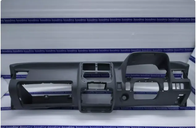
An Instrument panel is a control panel usually located directly ahead of the vehicle's driver, displaying instrumentation and controls for the vehicles's operation. These days car dashboards may include so many indicators like speedometer, tachometer, odometer, fuel gauge, turn indicators, gearshift position indicator, seat belt warning light, engine-malfunction lights, other features may include a gauge for alternators voltage, low feul indicator, low oil pressure and low tyre pressure indicator and faults in the ABS , airbags, lighting control, safety system, entertainment equipment, navigation system etc.,
Procedure:
Geometric topology:
1.The given part is imported into ANSA
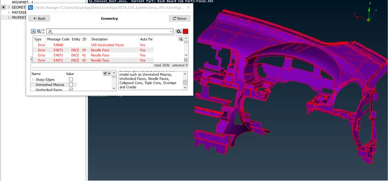
2.The component is checked for geometrical errors using the checks manager.
3.The Errors which are displayed is cleared by using the auto fix option in checks geometry and by also using the tools available in hot points, cons, faces and surface.
Geometric errors before topology:
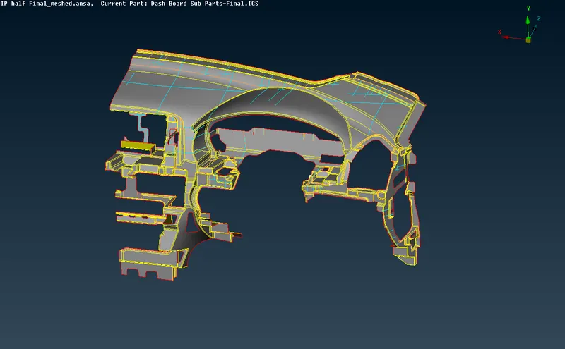
Model without geometric errors:

Mid surface Extraction:
The given model is complex and has variable thickness, hence different mid surface extraction methods is used:
1.OFFSET method: The offset option available in FACES module is used for extracting the midsurface of the outer circular surface.
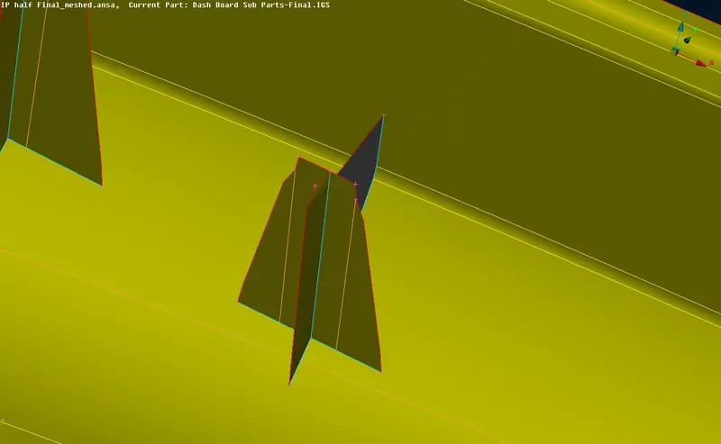
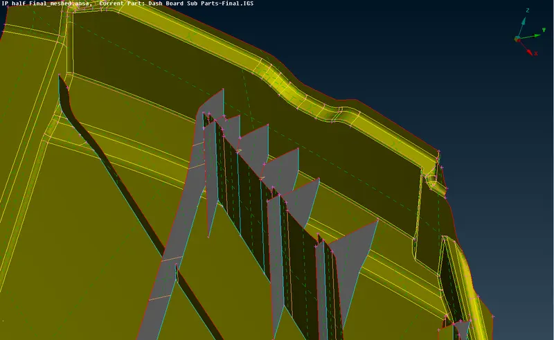
2.SINGLE-MIDDLE method: The single middle option available in FACES module is used for extracting the mid surface of ribs.
3.MULTI-MIDDLE: The multi middle option available in FACES module is used for extracting the midsurface of small ribs and supporting structures which are available in the component.
The Extracted Mid surface is as follows:
Base Componet
Extracted Ribs (samples)
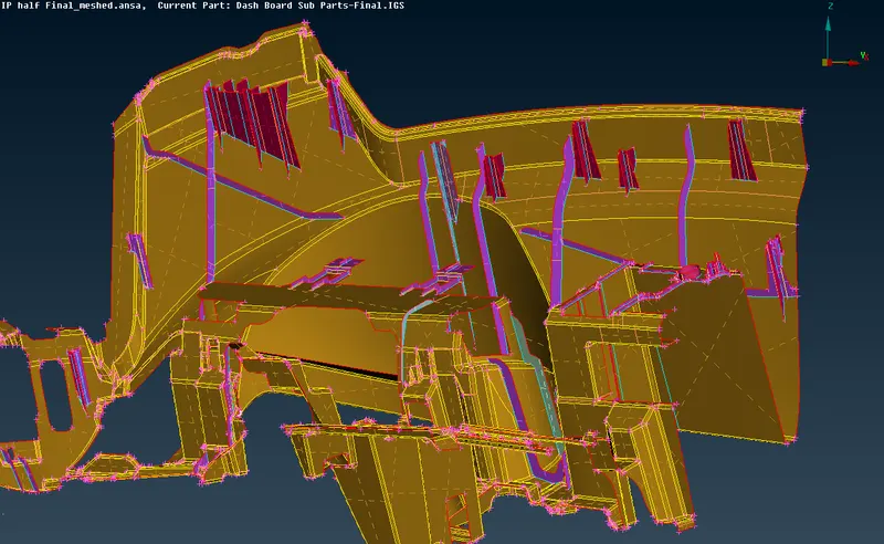
Ribs Extended to the base
ASSIGNING THICKNESS:
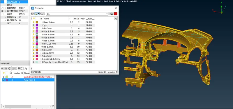
The thickness to the extracted midsurface is assigned in the Properties tab, the created midsurace is selected and renamed according to their names, the thickness values of all the part are entered and their type is chosen as PSHELL. The thickness is applied successfully.
Mid Surface with thickness assigned:
MESHING:
1.Once again geometric check is performed using the checks manager.
2.The given quality criteria and mesh parameters values are entered.
3.Mesh is generated using the batch mesh option.
4.The component is checked for quality criteria which is achieved by using various tools available in the modules like Cut, join, Num +/-, Reconstruct, Smooth etc.,
5.Smooth mesh flow is achieved.
Meshed Parts as follows:
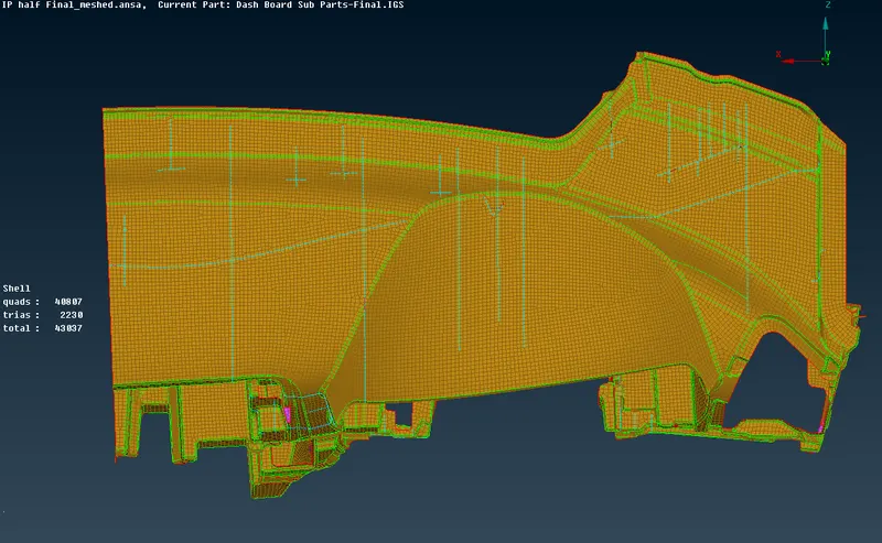
(i) Meshed Component Top View
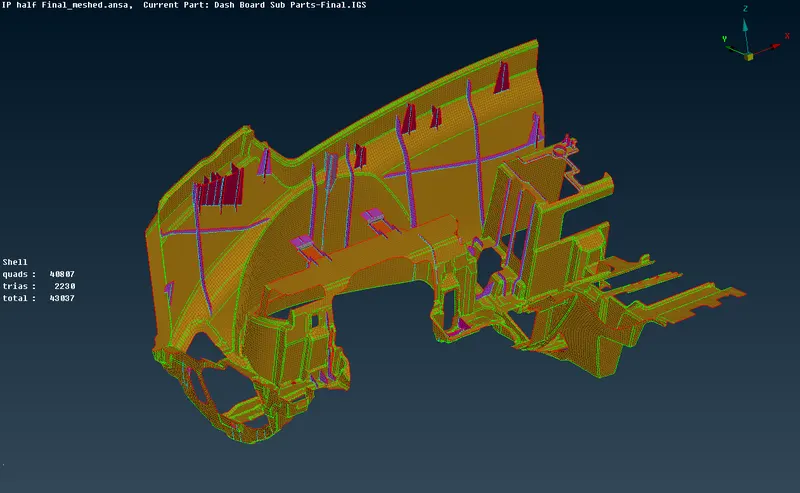
(ii) Meshed Component Isometric View (With ribs)
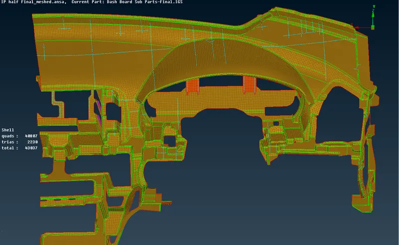
(iii) Meshed components Front view
Quality Issues Encountered:
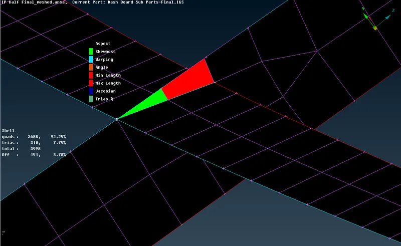
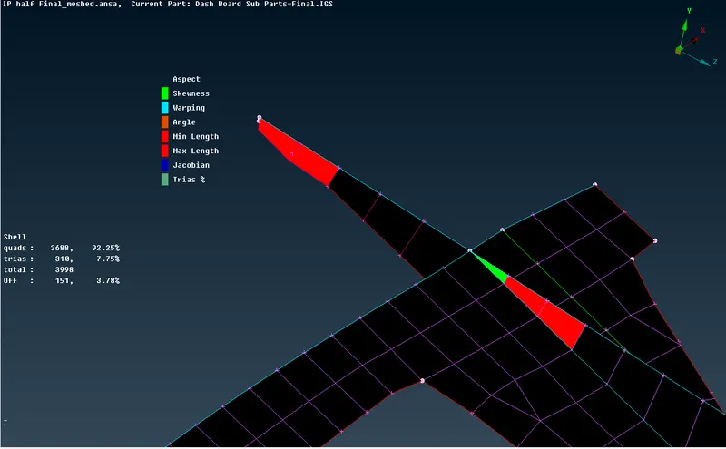
(i) Elements failing on Ribs
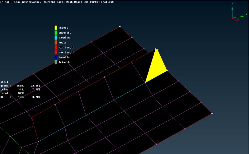
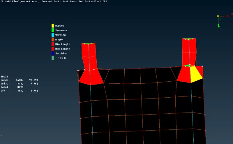
(ii) Elements Failing on Dog houses
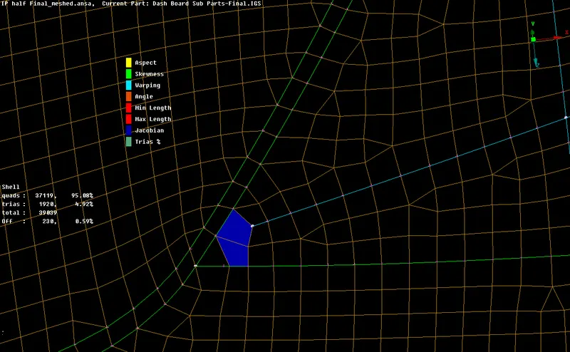
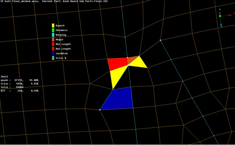
(iii) Elements Failing on base plate due to Extension of Ribs
Final Model Image:
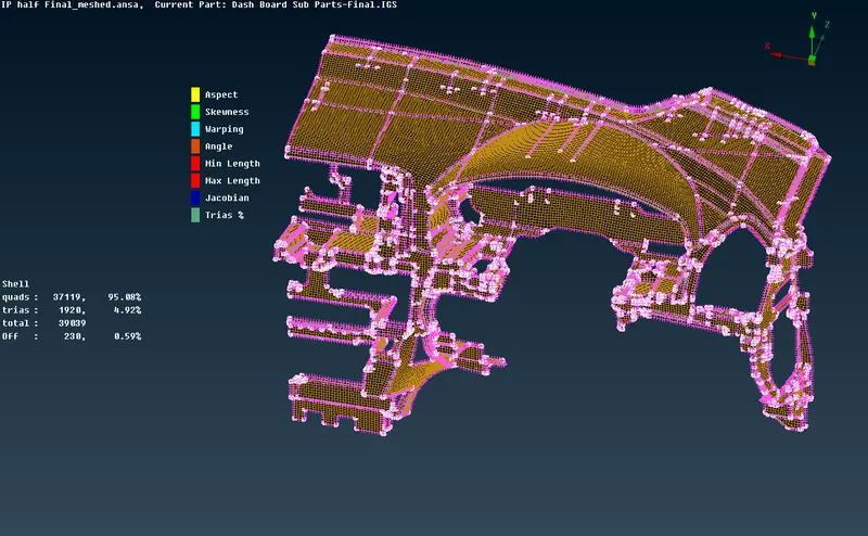
(i) Hidden mode view
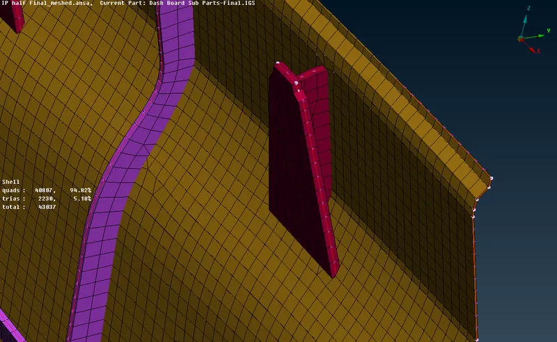
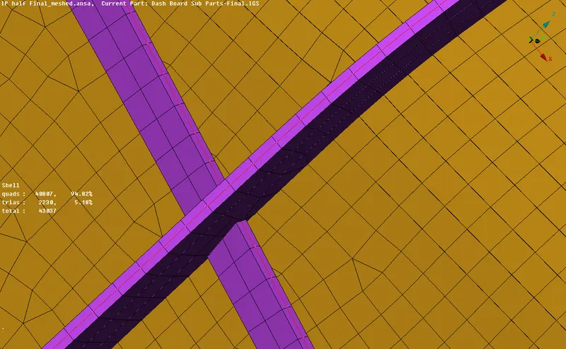
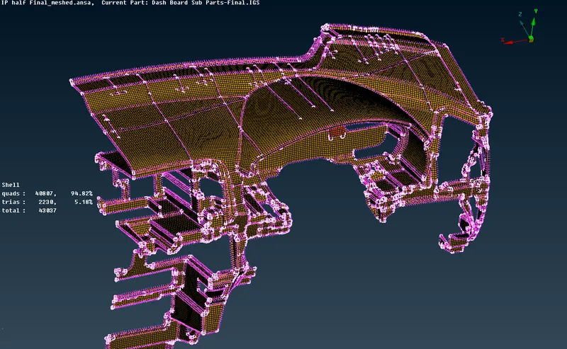
(ii) Detailed Element Representation
Learning Outcomes:
- Able to Fix topological errors.
- Understood how to take midsurface to complex geometry
- Aware of the imporatance of 2D elements and Shell meshing
- Understood the meshing approach of complex geometry
Conclusion:
The given component of Instrument panel is sucessfully imported into ANSA, geometric cleanup is done and 2D meshing is done according to the given quality criteria with smooth mesh flow is achieved.
Link for model: https://drive.google.com/file/d/1GCSMdrUvwaaVpql4gLWmHn_Iaf9MCiaI/view?usp=sharing