Project 1 - 2D meshing on the instrumental Panel
OBJECTIVE :
This Project aims to extract the midsurface and mesh the given Automotive IP Substrate with 2D shell elements by following the given quality criteria and mesh parameters.
Dashboard of an automotive :
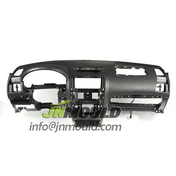
A dashboard (also called dash, instrument panel (IP), or fascia) is a control panel set within the centre console of a vehicle or small aircraft. Usually located directly ahead of the driver (or pilot), it displays instrumentation and controls for the vehicle's operation.
Usually, these dashboards are made up of plastic materials like Polypropylene based material and Polyurethane, Acrylonitrile Butadiene styrene etc such that they are covered with several high quality leather like Alcantara which are exposed to the user to give a pleasant feel while touching and a great visual appeal.
PROCEDURE :
1. Firstly, upload the given CAD model to the ANSA workspace and then check for the geometrical errors. Once the geometry is free from any errors then the geometry can be used to extract the middlesurface.
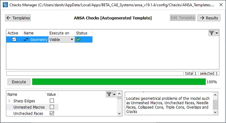
2. The CAD model has to be given TOPO to enclose all the unstitched surfaces and then any geometrical errors can be checked by using Checks >> geometry. All the imperfections in the geometry can be fixed easily by using the autofix command.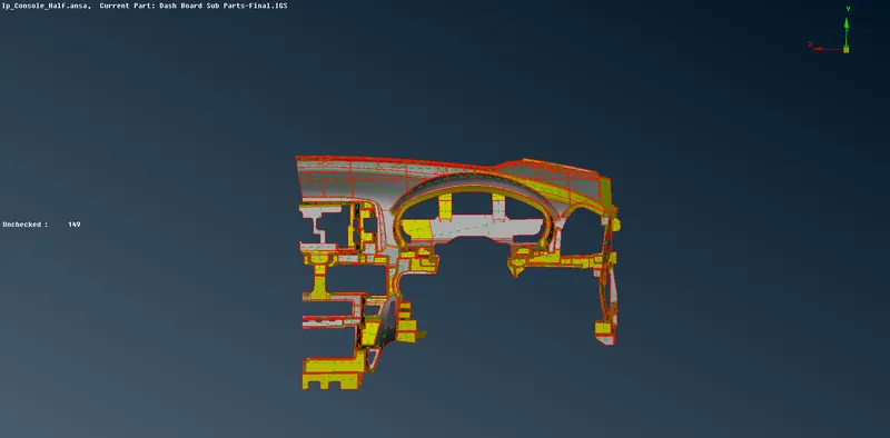
3. There are certain missing faces which can be fixed by creating new surfaces using Topo >> faces >> New >> fitted. Then, again the checks >> geometry is used to ensure whether all the geometrical errors have been fixed. 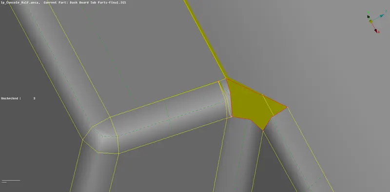
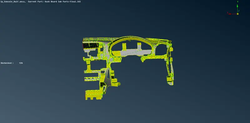
4. Now, the IP substrate has a major surface which is about 0.6mm thick. Generally, If the geometry has a thickness value which is much smaller than its span length then we use 2D shell elements to create the FE model and then assign proper thickness value and material to replicate the original CAD geometry. Here, the IP substrate has major surface which is of uniform thickness 0.6mm and there are other surfaces like ribs, dog house, small projections and other complicate geometry which are of different thickness. In this case we can use Automidsurface for the Base surface and then manual midsurface can be used to create the midsurface for those projections and dog houses,ribs etc.
Here, to capture the surface more precisely we use Manual Surface offset command to extract the midsurface for the base surface which is about 0.6mm thick.
Go to Topo >> Surface >> Offset >> Select the surface ( By feature angle to select the base surface alone ) >> Offset distance >> O.3
Once the base midsurface is extracted, seperate PID shall be assinged then and there to make the task easier and less time consuming. 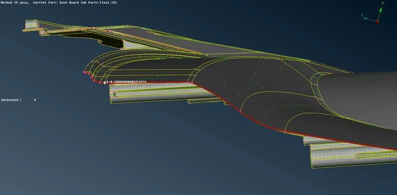
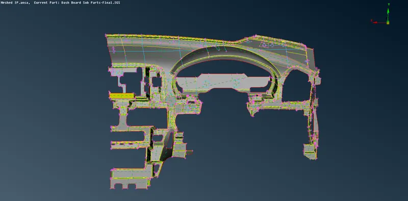
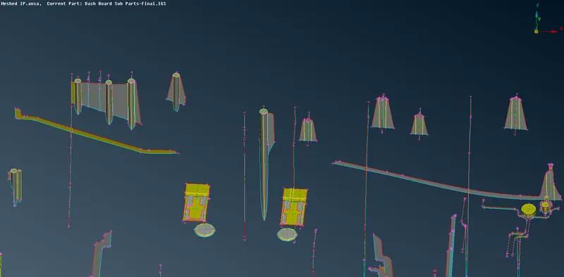
5. Now, after the base surface, the dog houses and the other ribs and projections should be worked on to get the midsurface. For dog house which are very smaller we can create the midsurface like cross pattern without extracting the cylindrical part. But for the other dog house which are comparitively larger, then it can be mostly extracted with cylindrical pattern.
For the ribs which are uniform thickness, then they can be worked with Topo >> surface >> Middle >> single / multi depending on dealing with number of ribs at a time. The middle surfaces should be extended to be attached to the dog house or the base surface such that it creates a triple con.
Once the middle surface is extracted, PID should be created for all the parts seperately with the thickness value properly mentioned.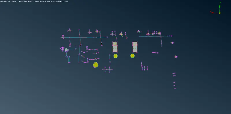
6. There are certain features which are present only one side, these were generally represented as solids however as we are dealing with 2D shell elements, we should create the middle surface by offsetting it to the base surface and extending and trimming them to replicate the projection.
The thickness value can be obtained by projecting the top surface of the projection to the base surface and then measuring the length and finding the difference between that value to the thickness of the base surface (0.6) which would give the thickness of the required feature. The offset distance would be half of the thickness value which is found. 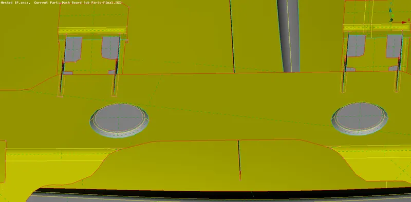
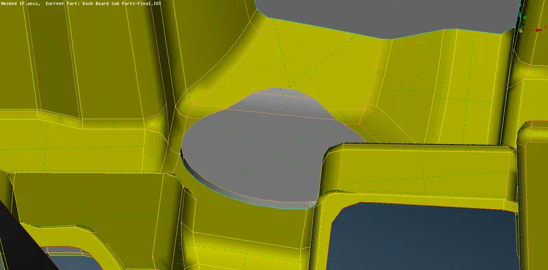
7. Once all the middlesurface are extracted and the PID's assigned, we can move on to the meshing part wherein all the mesh parameters and the quality criteria can be entered and followed accordingly.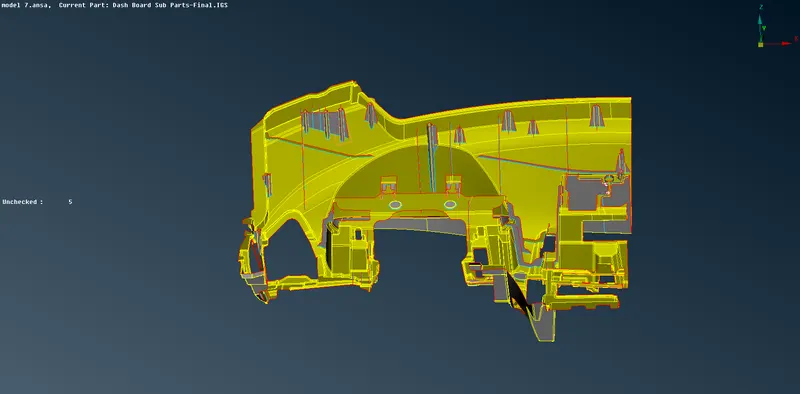
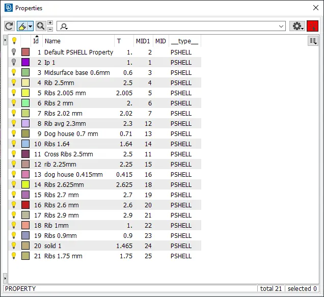
8. These are the mesh and quality criteria to be followed :
|
S.No |
Quality Criteria |
Value |
|
1 |
Target/Average length |
4 |
|
2 |
Minimum Length |
2 |
|
3 |
Maximum Length |
6 |
|
4 |
Aspect |
3 |
|
5 |
Warpage |
15 |
|
6 |
Skewness |
45 |
|
7 |
Jacobian |
0.7 |
|
8 |
Minimum Quad Angle |
45 |
|
9 |
Maximum Quad Angle |
135 |
|
10 |
Minimum Tria Angle |
30 |
|
11 |
Maximum Tria Angle |
120 |
|
10 |
Tria Percentage |
15 |
Now, to start off with, we can use either spot mesh or best mesh to create the mesh for the surface, Starting with the more complex region would provide with better mesh flow.
In this component, for the given quality criteria, the elements would mostly fail around the triple cons. So that can be accpeted in order to capture the features properly.
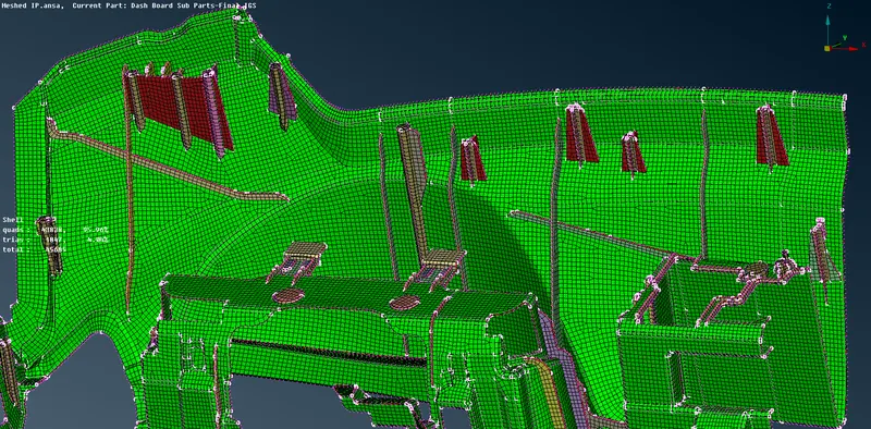
9. There are above 423 elements which were failing in this FE model to capture the feature properly with the given mesh pararmeters and quality criteria.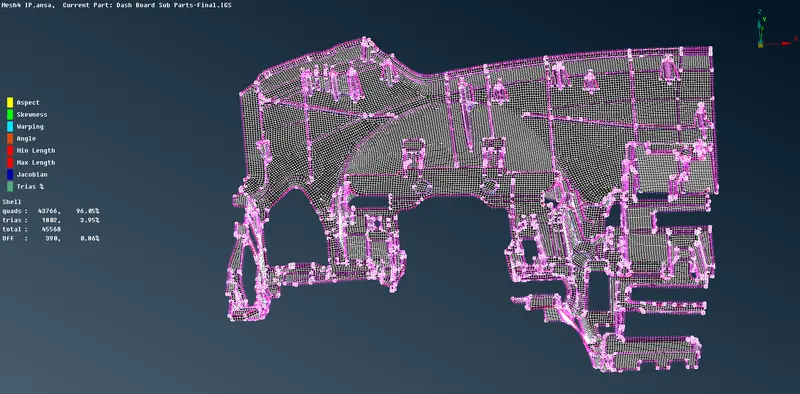
10. Now, once all the surfaces were meshed, we need to check for the element connectivity and deal with free edges between elements to ensure proper connectivity. Then go to Quality criteria >> Presentation parameters >> Check draw shell as solid. Thus, the thickness value to the corresponding surfaces would be assigned. Then the mesh can be released.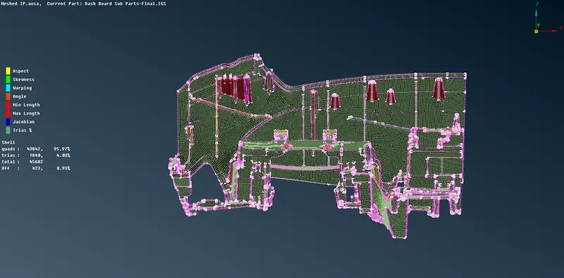
11. Since the process of midsurfacing and the meshing has been done manually and the failing of elements were left at the complex feature regions, the features were captured properly in this geometry. 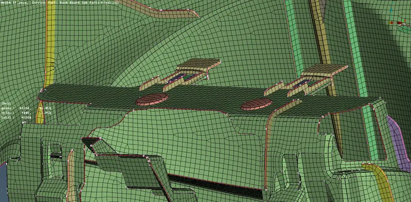
RESULT :
Thus, the given IP substrate has been properly meshed with 2D shell elements and the thickness value were assigned properly with all intricate features captured.
INFERENCE :
1. Midsurfacing and meshing of huge and complex component.
2. Modelling of complex dog house and ribs.
3. Expanding and joining ribs and dog house to base surface.
4. Resolving quality issues at complex parts to an acceptable level.