Project 1 - 2D meshing on the instrumental Panel
2D Meshing on the Instrumental Panel
AIM:
- To perform FE modelling of an Automotive Instrumental Panel trimed component by considering the given element Quality criteria using 'ANSA preprocessing tool'
OBJECTIVE:
- For the given component, check for the geometrical errors and mesh with the given element Quality criteria.
- After meshing the component the thickness has to be assigned.
2D element Quality criterias
|
S.No |
Quality Criteria |
Value |
|
1 |
Target/Average length |
4 |
|
2 |
Minimum Length |
2 |
|
3 |
Maximum Length |
6 |
|
4 |
Aspect |
3 |
|
5 |
Warpage |
15 |
|
6 |
Skewness |
45 |
|
7 |
Jacobian |
0.7 |
|
8 |
Minimum Quad Angle |
45 |
|
9 |
Maximum Quad Angle |
135 |
|
10 |
Minimum Tria Angle |
30 |
|
11 |
Maximum Tria Angle |
120 |
|
12 |
Tria Percentage |
15 |
NOTE : In this model, there will be some off elements found in the chamfer region which cant be removed. It is acceptable as it is been found due to the presence of triple cons on the chamfered surface. Due to those triple cons there will be some quality criteria failure which can be accpetable and those quality fails can be neglected
PROPERTIES OF THE COMPONENTS:
- Materials which is having less than or equal to 6mm can be meshed with 2D Meshing.
- In 2D Meshing, we can classify the materials into two types.
- Sheet Metal Component
- Plastic Component
- The material which is having Linear Thickness throughout the Body is known as 'Sheet metal'
- The material which is having Non Linear Thickness is 'Plastic Material'.
What is Instrumental Panel?
- The portion of the dashboard which sits directly behind the steering wheel is called the Instrument panel.
- This panel houses various gauges and lights which provide the driver with important information about the status of the vehicle.
- It displays instrumentation and controls for the vehicle's operation.
- Main parts of Instrumental Panel
- Speedometer
- Tachometer
- Odometer
- Fuel gauge
- Temperature gauge
- Turn signal indicators
- Gear display
- Warning lights
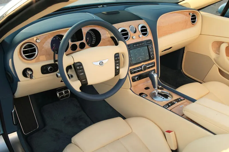
- The above images shows the Instrumental Panel of 'Bently continental GTC' car.
PROCEDURE:
- CAD SET UP
- CAD Geometry
- Model Clean Up
- CAD MODELING
- Meshing
- BOUNDRY CONDITIONS SETUP
- Load Cases
- Final check for the Quality of elements
PREPERATION OF MODEL FOR MESHING: (Part -1)
IMPORTING THE MODEL TO ANSA
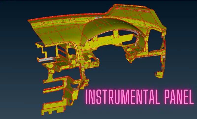
- We can check for the existing PID’s in the ‘Property Card’
- This is the single component, there is only one PID available in this model.
Steps to be followed in Begining
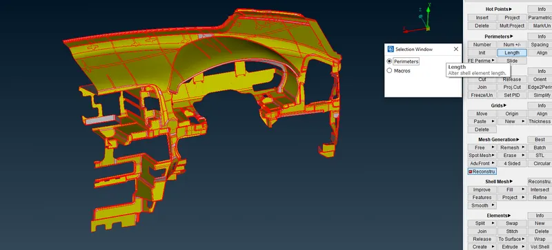
- Then we have to set 'Cons Resolution' for the parent geometry, It is present in (Mesh module --> Perimeters Group --> Length) for both Macro areas and perimeters length.
- Target length is 1mm, it will be used for achieve the target length while meshing.
- After Importing the geometry, we have give topo to make connectivity of single Cons using (Topo module --> Faces group --> Topo)
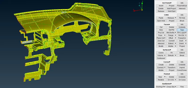
- Next step is Orient (Topo module --> Faces group --> Orient), this Helps to get the same color either Grey or Yellow color one side.
TOPOLOGY CLEAN UP: (Part - 2)
- Now it is time to Geometry Cleanup, to generate FEM we clean up the geometry
- Before start meshing Geometry Check is necessary, because in Original CAD geometry there might be some errors like Triple cons, Cracks, unchecked faces, Surface patch up, Converting single cons to double cons in necessary areas.
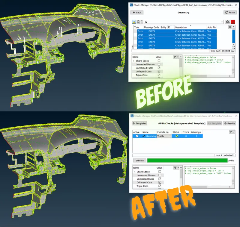
- Check the geometry for errors or sharp edges or single cons or crack faces using (Checks --> Geometry)
- In our given component some errors were present when perform the geomentry check.
- In ANSA there is an option called 'AUTO FIX', i used this function to fix my errors, in some cases the errors cannot fix by ansa, we have to fix them manually.
THICKNESS CHECK
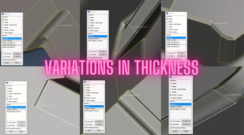
- We can see it clearly this 'Automotive IP' component has Non uniform thickness so we can consider this as Plastic Component.
MID SURFACE CREATION: (Part - 3)
- We have prepared geometry. Next step is creating the mid-planes
- Mid is the neutral pahse which is been generated from the CAD which is imported or given to us.
- The conversion of 3D cad to 2D cad is happening in mid surface generation.
- The mid surface is generated to reduce the complexity as by simplifying the cad model we get more accurate simulation results in shorter time.
Steps to be followed before casting
- We have set the Quality criteria and mesh Parameters properly as per the given requirement, because when we use the 'CASTING' option, the mesh also be Generated automatically.
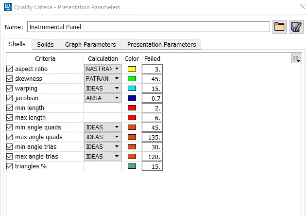
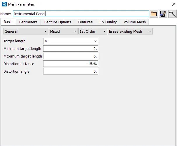
-
There are Two methods to create Mid plane
- Manual Method
- Automatic Method
- In this model i used the Auto mid.surface option to create the Mid Surface, using the Option (Topo Module --> Faces Group --> Mid.surface --> Casting)
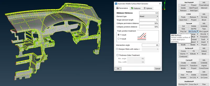
- The Reason I go with the Auto method because this model has different thickness in various areas, so the mid surface extraction save my time a Bit in auto method
- On a 'Single middle mouse button' confirmation the mid surface creation is done easily.
EXTRACTED MID SURFACE PID
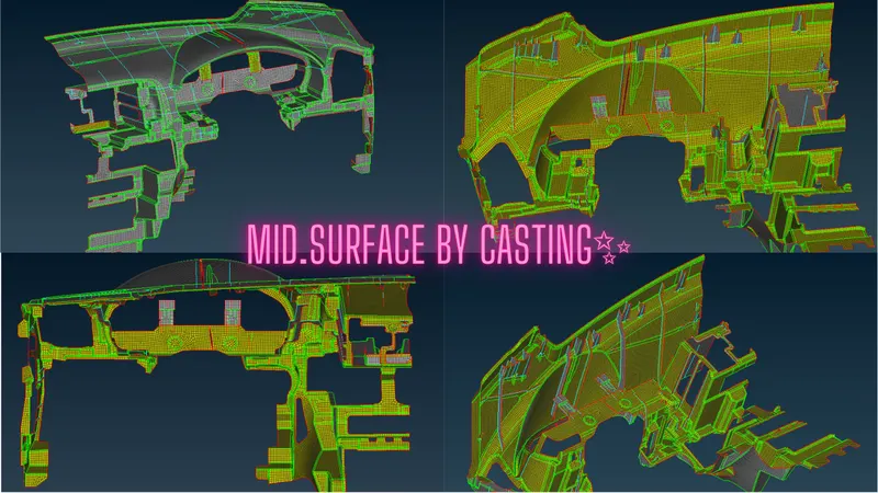
- Mid.surface that created by the 'CASTING' is not that much good.
- Some feature areas are not properly captured and not aligned compare to the 'PARENT GEOMETRY'
- So it is our responsibility to clean it up and make it proper.
HERE ARE THE SOME EXAMPLES OF DISTORTED AREAS OF OUR CASTING RESULT
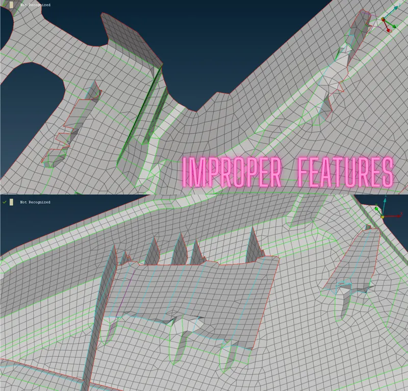
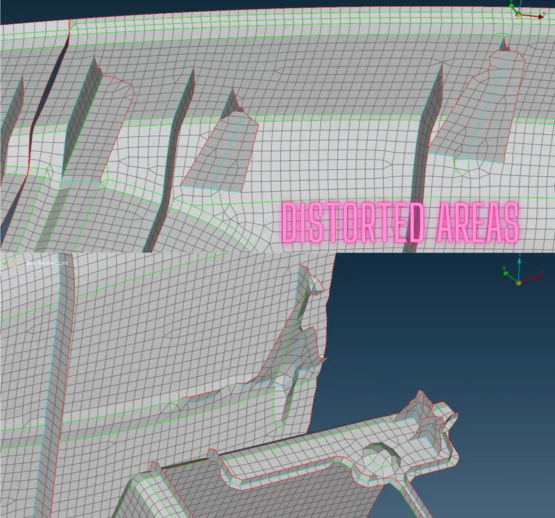
- These areas can not capture during CASTING operation, here some features and some fillet areas not properly created.
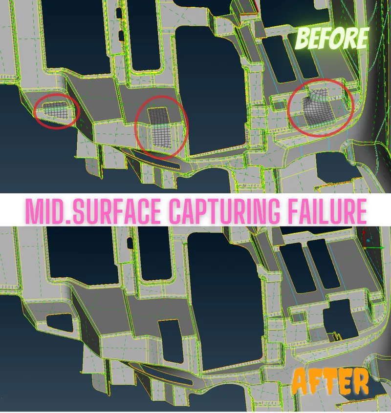
- The above image shows some areas feature alignment also wrongly captured by casting
- we can correct them with the help of the ALIGN MANAGER.
ALIGN MANAGER FUNCTIONS
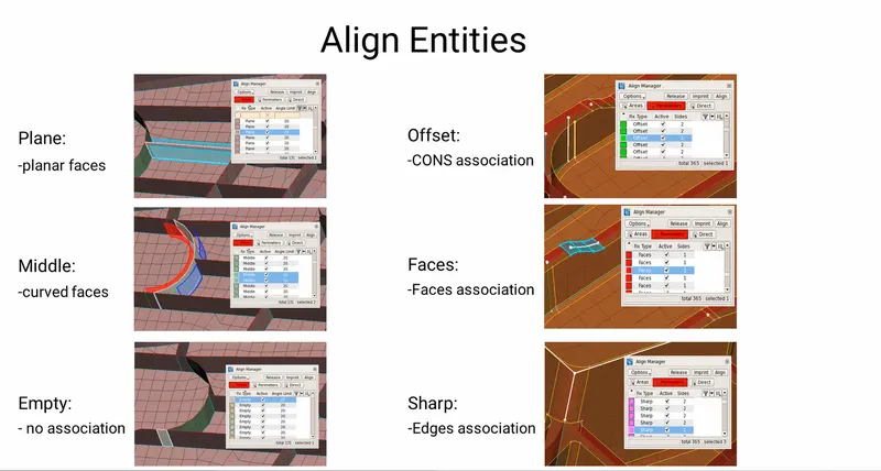
- Above image show the main functions of align manager which is present in (Topo module --> Faces --> Mid.surface --> Align manager)
FINAL CHECKING OF MESH: (Part - 4)
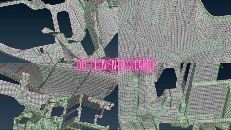
- Once we done with the clean up and corrections of the 'CASTING RESULT', need to work on the OFF ELEMENTS and the MESH FLOW.
- Some areas are not meet the 'Quality Criteria', where the areas Triple Cons closely present in the model, Elements are failing.
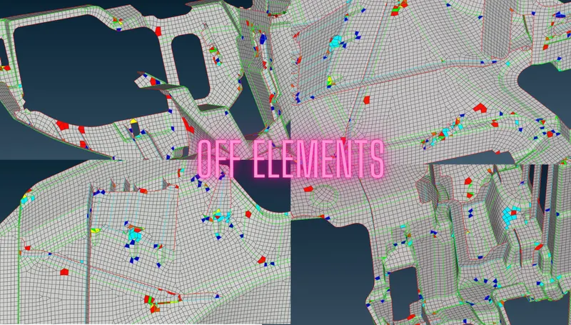
- After work on the mesh flow and these elemental failures by manually.
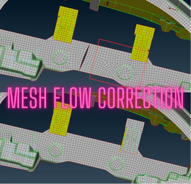
- The above image shows difference of casting and manual meshflow
HERE IS THE BEFORE & AFTER RESULT OF FINAL MODEL
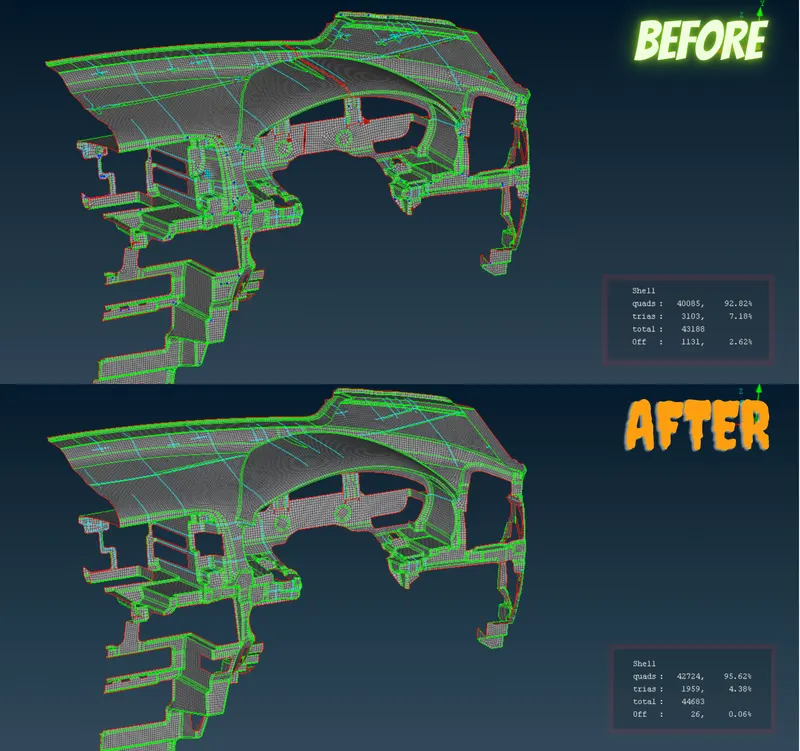
- The above picture shows that the result, after I corrected the Distorted casting Result.
- In this window the Off elements percentage was high at begining.
- After dealing with Off elements and mesh flow, this is the Final outcome of the Automotive Instrumental Panel.
ASSIGNING THICKNESS TO THE MID SURFACE:
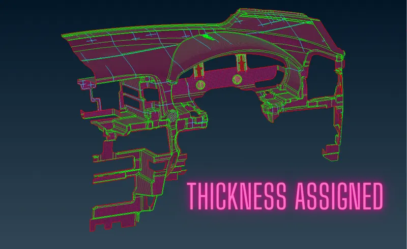
- Thickness has been assigned to the different thickness areas individually, using (Mesh module/Grids/Thickness/Convert)
RESULT OUTCOMES:
- Finally achived Trias with 4.38% and OFF Elements with 0.06%
- Good Mesh flow maintained, no trias touching on the Circle and no trias touching at the Free end.
- No Rottating Quads keep maintained, No Opposite Trias are present in the FE model.
- No any other Feature Lines missed while meshing.
- Missed Ribs has been captured properly as per the Reference of Parent Geometry.
CONCLUSION AND LEARNING OUTCOMES:
- Hence, the geometrical errors and 2D mesh, with the given element Quality criteria has been performed successfuly for a given Automotive IP Trim component.
At the end of this project,
- Easily perform FE Model building for any complex automotive components with a good mesh flow.
- Learned a lot of new ideas and fast way to complete the model requirments.