Project 1 - 2D meshing on the instrumental Panel
2-D MESHING OF INSTRUMENT PANEL
AIM : Perform the 2-D meshing on the given automobile component which is the instrument panel by proper mesh parameters and quality criterias as follows.
|
S.No |
Quality Criteria |
Value |
|
1 |
Target/Average length |
4 |
|
2 |
Minimum Length |
2 |
|
3 |
Maximum Length |
6 |
|
4 |
Aspect |
3 |
|
5 |
Warpage |
15 |
|
6 |
Skewness |
45 |
|
7 |
Jacobian |
0.7 |
|
8 |
Minimum Quad Angle |
45 |
|
9 |
Maximum Quad Angle |
135 |
|
10 |
Minimum Tria Angle |
30 |
|
11 |
Maximum Tria Angle |
120 |
|
10 |
Tria Percentage |
15 |
INTRODUCTION :
Meshing is the process of turning irregular shapes into more recognizable volumes called elements. In Finite Element Analysis (FEA) the goal is to simulate some physical phenomena using a numerical technique called the Finite Element Method (FEM). To quantify physical phenomena such as wave propagation or fluid flow we must use mathematical equations.
Here a automobile component which is the instrument panel is provided to perfrom 2-D mesh. By observation, we came to know that it is a plastic component. Since it is a plastic component, we are using Casting method to perform the operation.
DESCRIPTION:
Any continuous object has infinite degrees of freedom (DOF) which makes it impossible to solve using hand calculations. So in FEM, we create a mesh which splits the domain into a discrete number of elements for which the solution can be calculated. The data is then interpolated across the whole domain.
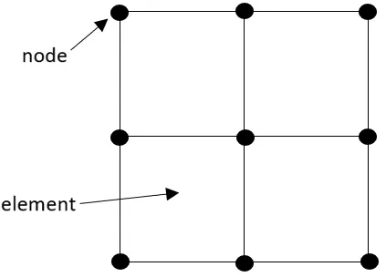
Meshing is one of the key components to obtaining accurate results from an FEA model. The elements in the mesh must take many aspects into account to be able to discretize stress gradients accurately. Typically, the smaller the mesh size, the more accurate the solution as the designs are better sampled across the physical domains. The trade-off is that the higher the accuracy, the larger the simulations become and thus solve times are extended. There is no point in spending extra hours running a simulation with a dense mesh if a coarser mesh will give you the results you need! Engineers often perform convergence studies to obtain the optimal balance between accuracy and solve time.
Ansys meshing capabilities help reduce the amount of time and effort spent to get to accurate results. Since meshing typically consumes a significant portion of the time it takes to get simulation results, Ansys helps by making better and more automated meshing tools.
2-D Meshing: The 2D Mesh module is used to construct two-dimensional finite element meshes. The mesh consists of nodes that are grouped together to form elements. Numerous tools are provided for automated mesh generation and mesh editing. 2D meshes are used for SEEP2D modeling and to aid in the construction of 3D meshes.
PROCEDURE :
1. The first step is to import the geometry to the ANSA workspace.
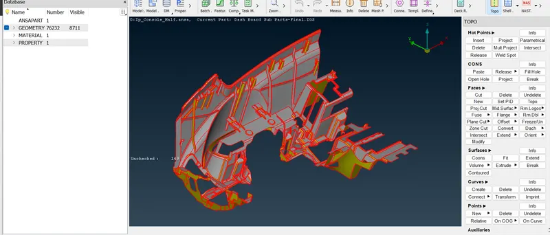
2. Inorder to view the model in a better way, perform the topo operation. Then, the model will be stitched properly and the edges and the geometry can be well visualized. Topo module > Faces > Topo
Orient option can also be used to obtain every face in a single direction. Topo Module > Faces > Orient
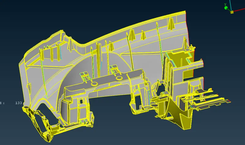
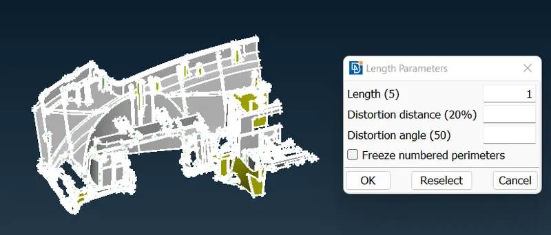
3. The length preset is the next step. While importing, the edges or the holes are not properly catched. Inorder to view those edges properly, we have to provide the preset length to 1 mm. We have to preset it in perimeter as well as macros option.
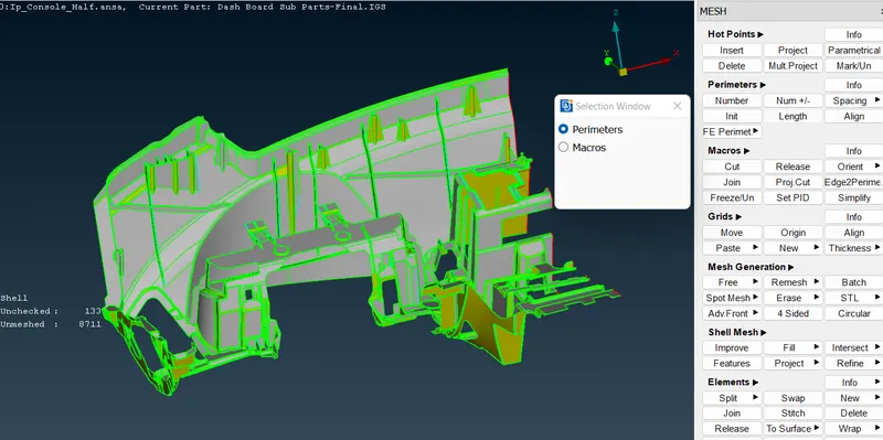
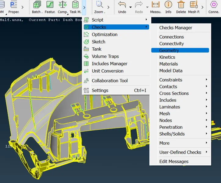
4. The geometry is to be checked inorder to find out the unwanted faces, triple cons, unchecked faces etc in the model. If these errors are present in the geometry without removing, these may affect our meshed model and geometry. The errors can be autofixed and manually fixed. Tools > Check > Geometry.
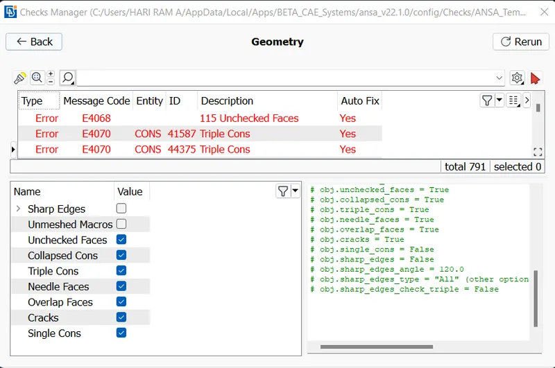
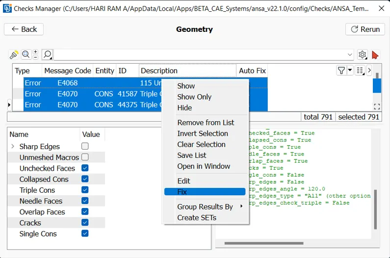
After fixing the errors by autofix and manual method, recheck the model for confirmation. If the check status is visible, then move on to further steps.
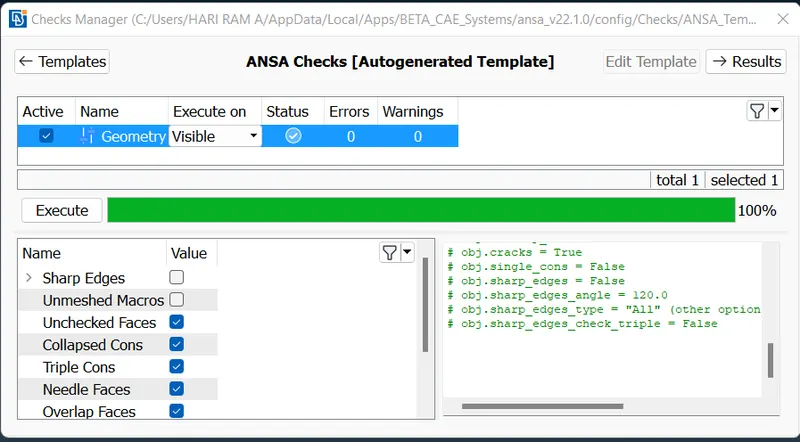
5. Since it is a plastic component, the casting method can be done. In casting operation, the mid surface as well as the mesh is autogenerated. So, provide the mesh parameters and quality criterias before doing the casting.
Topo Module > Faces > Mid Surface > Casting / Extrusion.
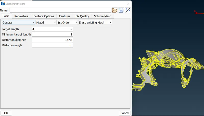
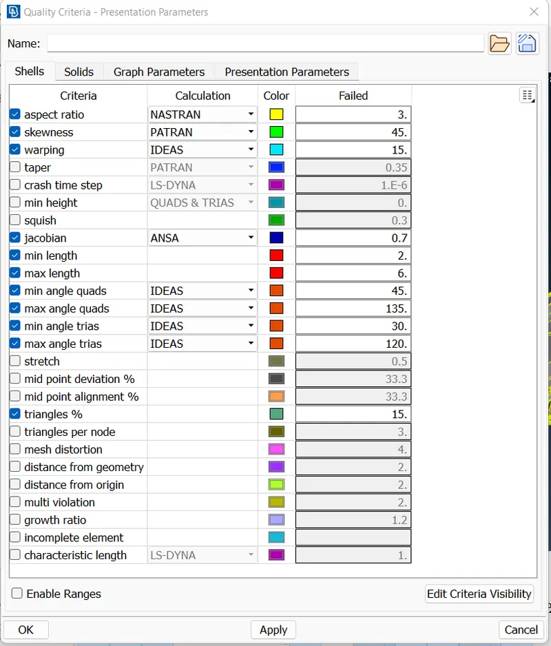
The casting parameters to be given are target length, minimum thickness.
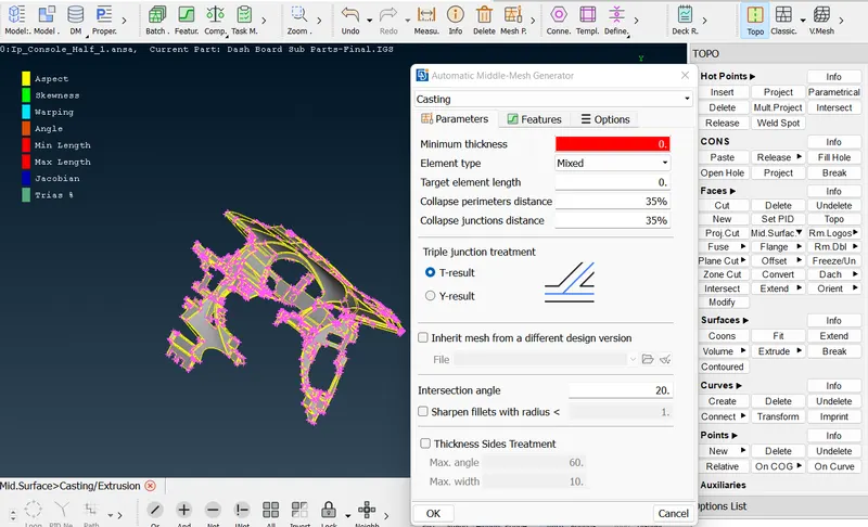
Here, provide the target length as 4 mm and minimum thickness as 0.5 mm.
The casting result obtained is shown below.
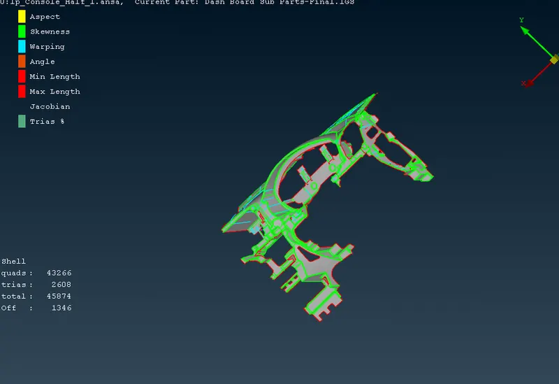
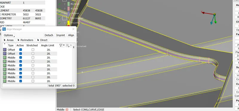
6. After getting the casting result, we should check for the align manager tab. Align manager is the tool to let us know about the method, ANSA has taken to extract the mid surface. Through align manager , we can know about the definitions given for an area as well as the perimeters. Also if these are not properly defined, we can manually edit or create new definitions.
The align manager tab is given below. Topo Module > Faces > Mid surface > Align Manager.
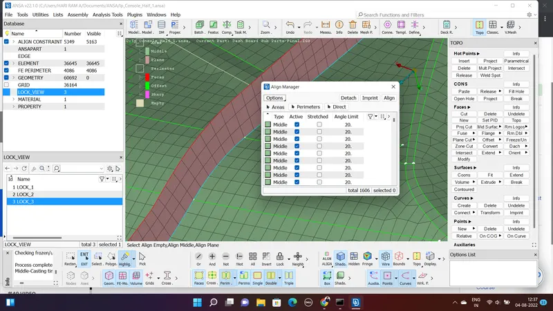
To know how the align manager works, some features in that model can be properly defining is as follows.
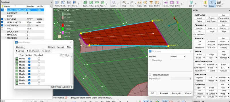
- The rib feature in the below figure should undergo proper definition puropose and to be extract the mid surface and mesh it accordingly.
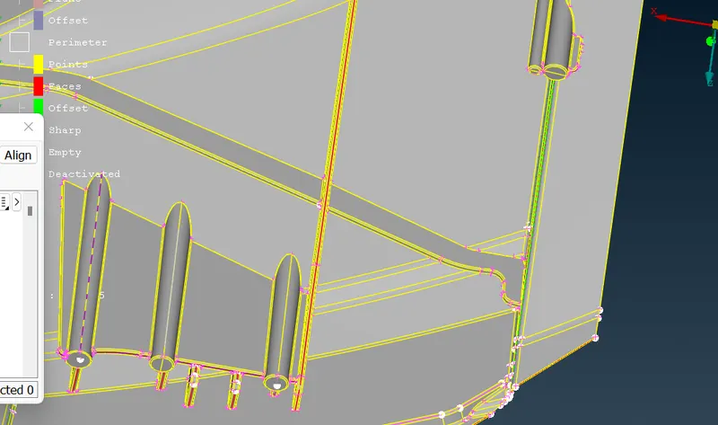
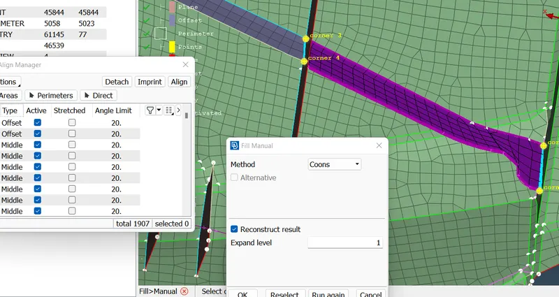
This can be done by capturing the base curves of that rib and that should be imprinted to the base of FE. Then obtain the middle curves for the rib and fill the space between both these perimeters.
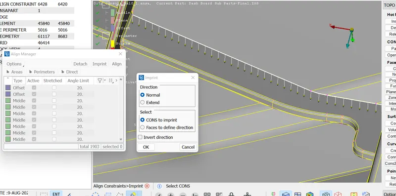
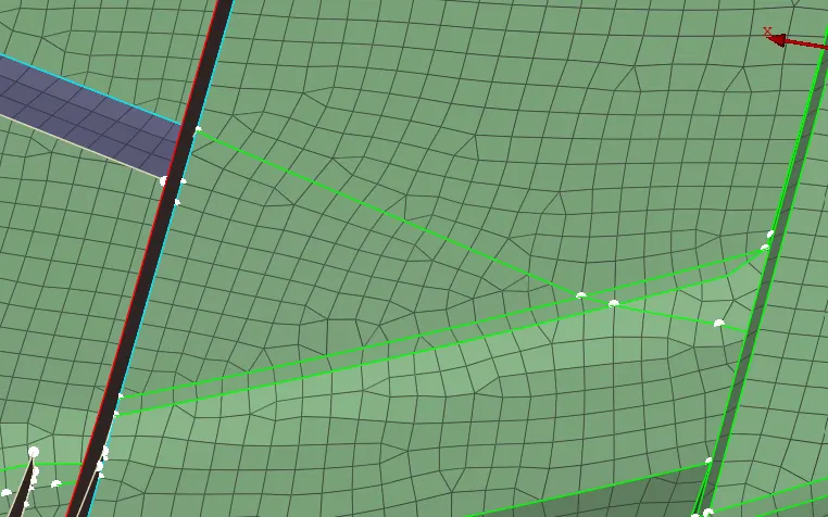
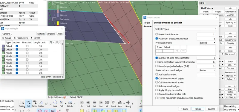
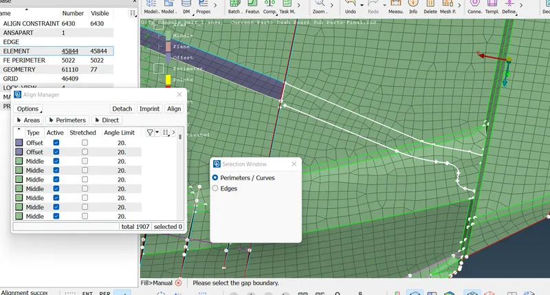
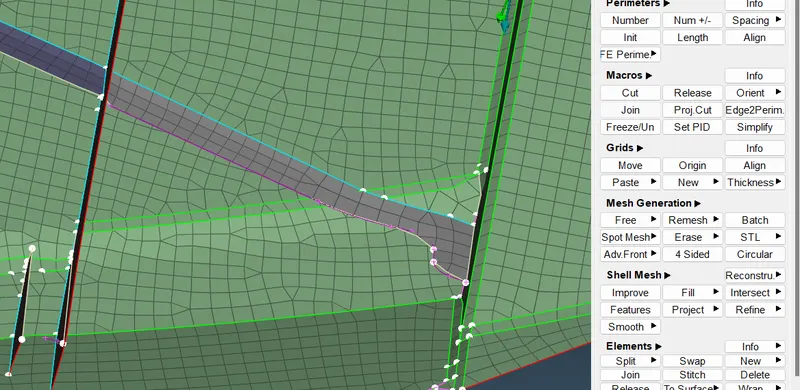
The newly created mesh face will not be defined. These are to be defined properly. Here it is better to defined it with offset option. The offset distance and face should be properly selected.
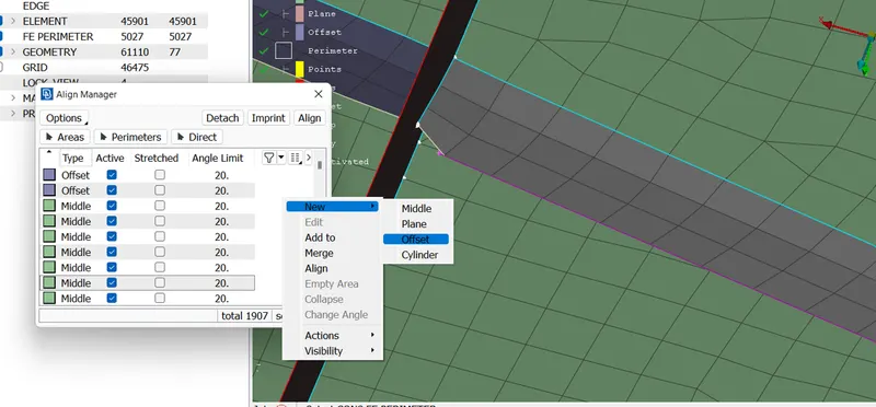
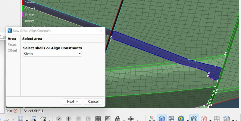
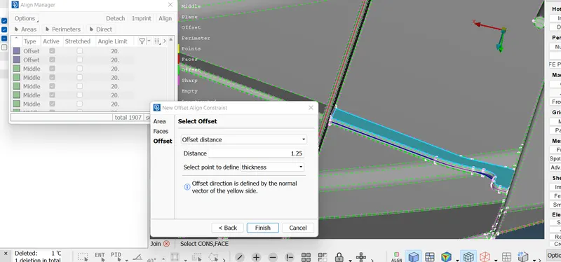
In this way we can define the faces properly.
- Another face is to defined as follows. There it is using middle option.
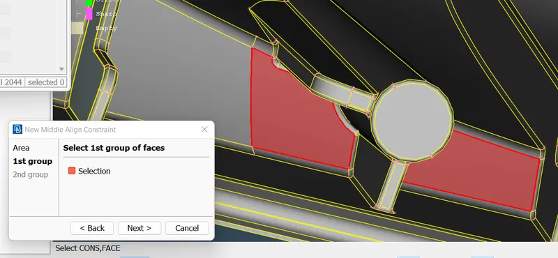
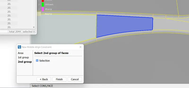
The areas and perimeters which are defined empty in align manager is to be given proper definition and after that move on to improper definition faces.
7. The next step after using align manager is to assign property. In casting process, the properties for variable thickness can be automatically assigned. Classic Mesh Module > Grids > Thickness > Convert.
The details needed to assign the thickness is to be given properly give create.
The property tab after thickness assignment is given below.
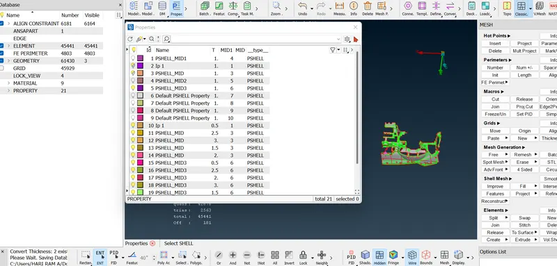
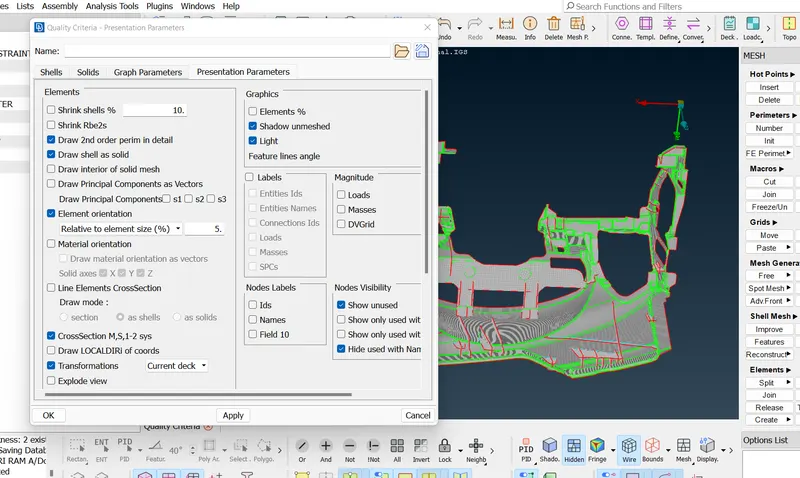
8. The final step is to enable the draw shell as solid option in the presentation parameters option in the quality criteria tab.
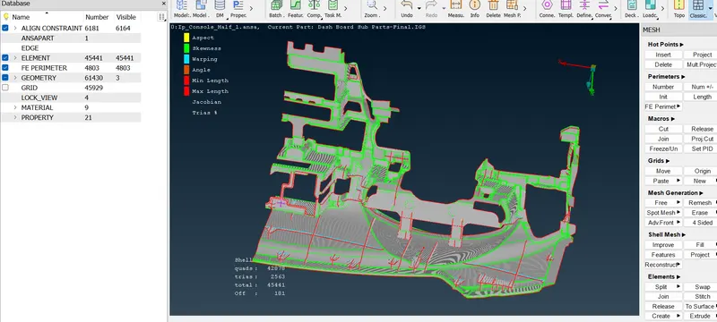
Tools used to define the features, areas and perimeters are as follows.
- Middle Curve
- Create Curve
- Cons2curve
- Fill shell elements.
- Align in Grids
- Cut macros
- Insert/ Delete hot points
- Paste nodes.
- Connect Middle mesh module
- Split elements
- Swap elements
- Join elements
LEARNING OUTCOMES:
The instrumentation panel 2-D meshing project helps to learn various things to be done in the process. They are
- Casting process inorder to generate ayto mid and mesh as well.
- Align manager usage.
- Creating definition for the areas, perimeters, faces in align manager.
- Use of various tools which helps to create surface or face.
- Thickness assignation in casting process
In total, casting and align manager uses a plastic component to perfrom 2 D Mesh in a fast way than other methods.
CONCLUSION :
The component to perfrom the 2-d mesh is done successfully.