Photo Realistic Rendering
Aim:
- The objective is to sketch and design every exterior parts of american chopper using part modelling through solidworks software.
- To assemble the parts that are modelled using part modelling in assembly environment.
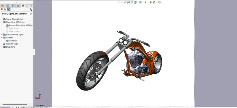
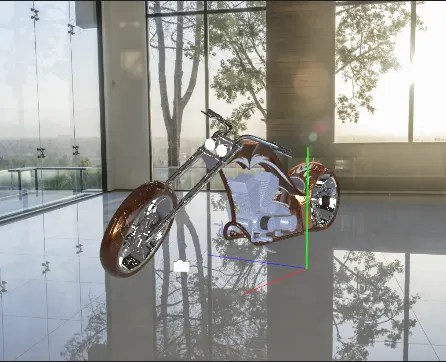
- To obtain a photorealistic rendering of american chopper using photoview 360.
Introduction:
The design of american chopper includes the part modelling and also the assembly of those parts modelled to be assembled with proper plane alignment and connections. The parts that we are modelling is in the order given below.
- Transmission Belt
- Kickstand
- Front Fender
- Rear Fender
- Chain
- Oil Tank
- Pedal
- Front Wheel
- Rear Wheel
- Front Fork
- Chassis
- Engine
- Gas Tank
Part modelling:
Part modeling is the process of creating a virtual prototype of something which can be obtained by modeling each individual part separately, which can then all be assembled together to create the model of the final product.
Parts Description :
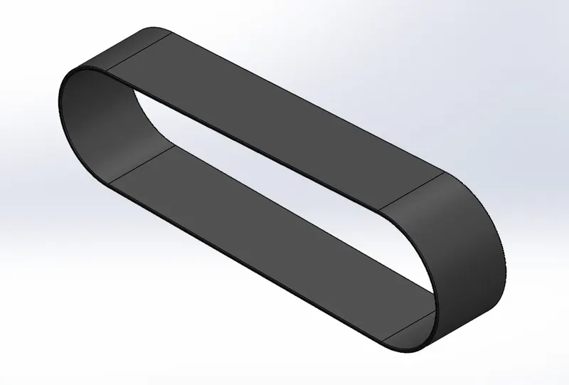
1. Transmission Belt:
Transmission Belt is a belt drive used for power transmission that uses a flexible strip.
Features used to create:
- Sketch : The sketch is the basis for a 3D model. You can create a sketch on any of the default planes (Front Plane, Top Plane, and Right Plane), or a created plane.
- Offset: It creates a copy of existing sketch at the required distance in the direction parallel to the original sketch.
- Extrude Boss: The extrusion commands represents the solid extrusion in positive or negative directions depending on the requirement.
- Fillet: Fillet command is used to make the sharp edges rounded and also it will reduce the stress concentration in the sharp edges.
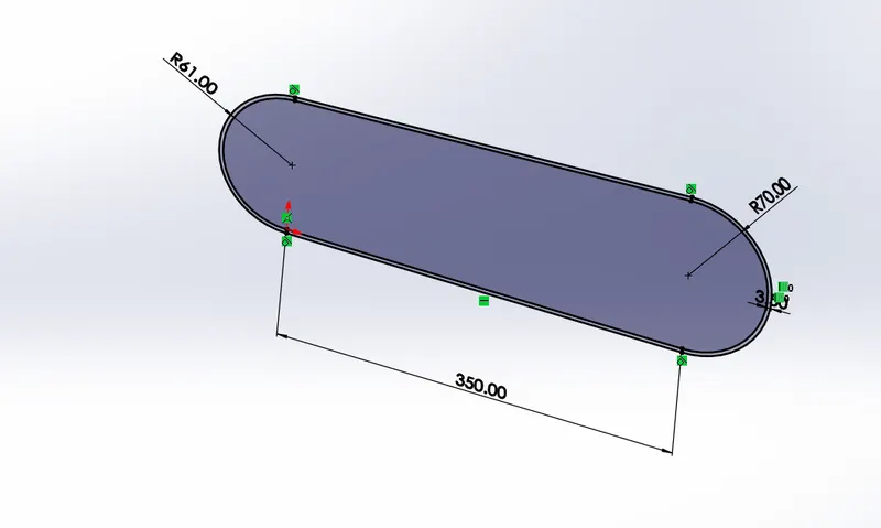
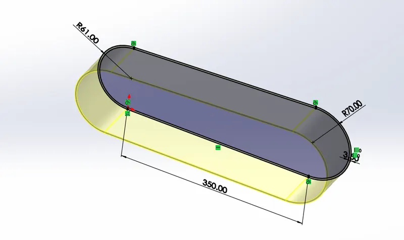
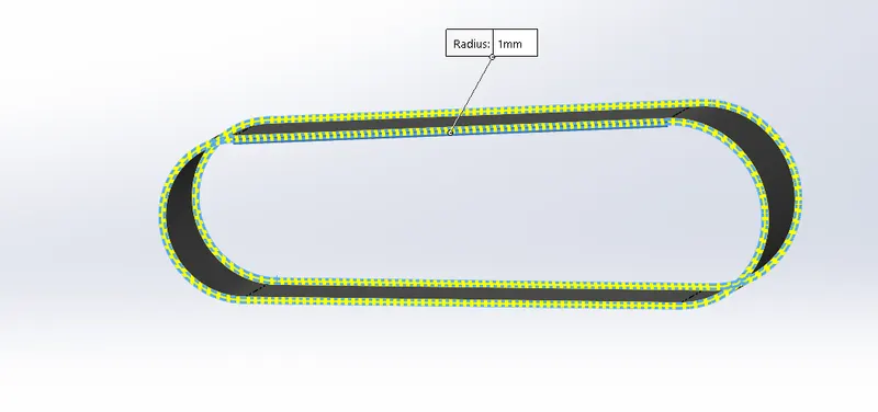
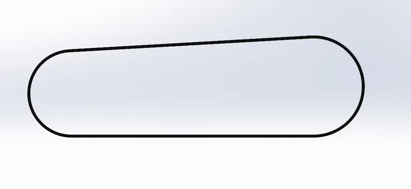
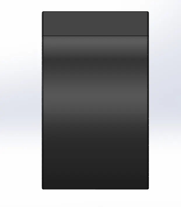
Views of Transmission Belt:
Front View:
Side View:
Isometric View:
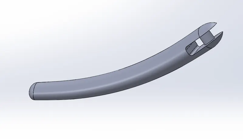
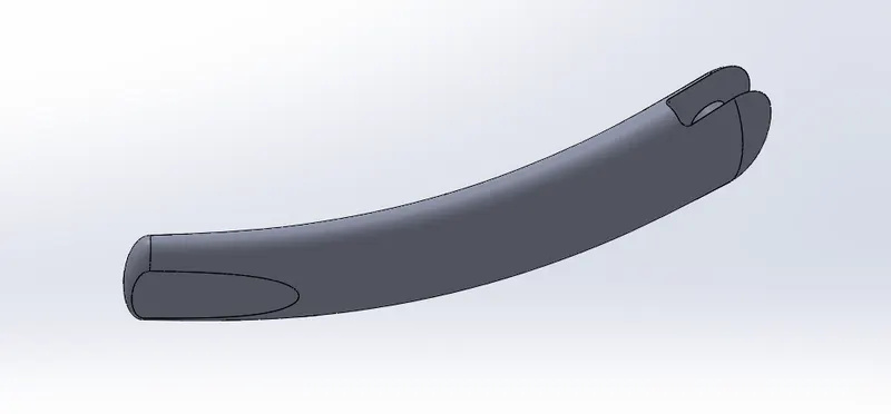
2. Kickstand:
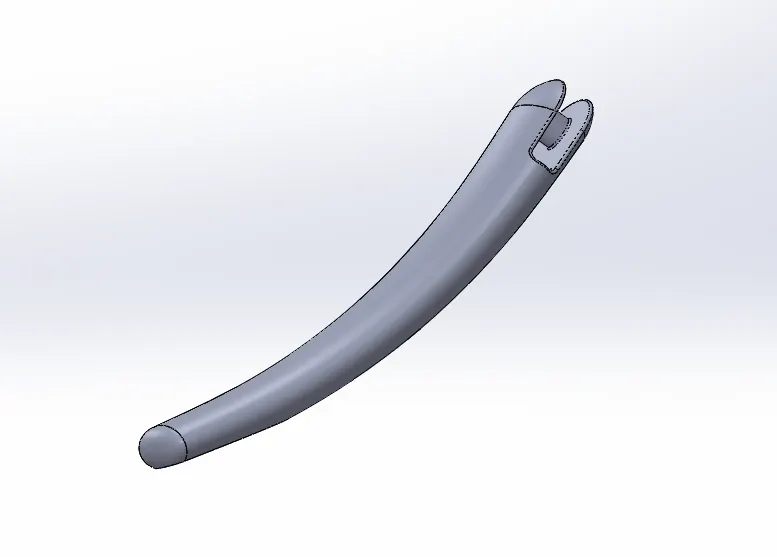
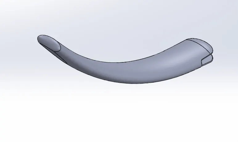
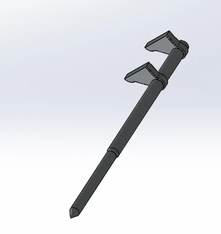
Kickstand is the part which holds the 2 wheeled vehicle upright when they are not ridden. It is included as a safety part in the 2 wheeled vehicles. It is a swivelling component, which is pivoted to the chassis and it can be kicked to a certain degree when drive the vehicle.
Features used to create:
- Sketch
- Loft : Loft command is used to create complex geometries through some profiles.
- Dome : It is a hemispherical structure over the surface or face.
- Extrude Cut : Extrude cut is the command used to remove unwanted materials from the solid model.
- Split : It is to seperate different parts of the model by considering a seperation to remove the unwanted edges. It seperates a single surface to multiple surfaces.
- Fillet
- Extrude Boss
- Appearance
Steps followed:
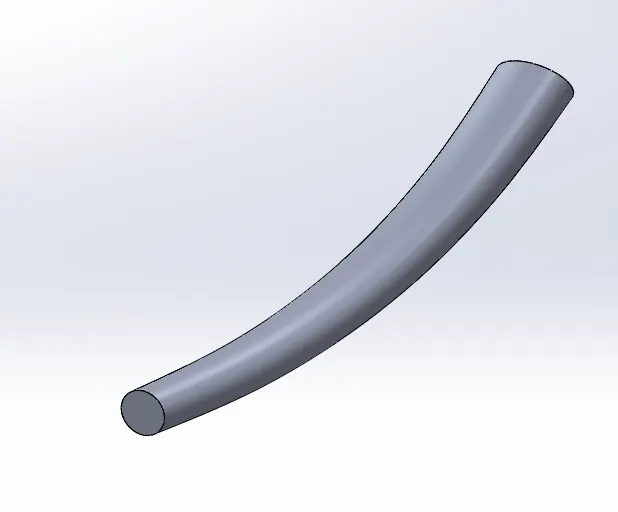
- Sketching a spline from the center of the midplane and creating a plane at one end.
- Lofting through the spline centerline and making the both ends elliptically domed.
- Creating a flat surface at base by using split command in the created plane and use extrude boss to pivot in the chassis.
- Applying filleting to round up the edges and also give appearances.
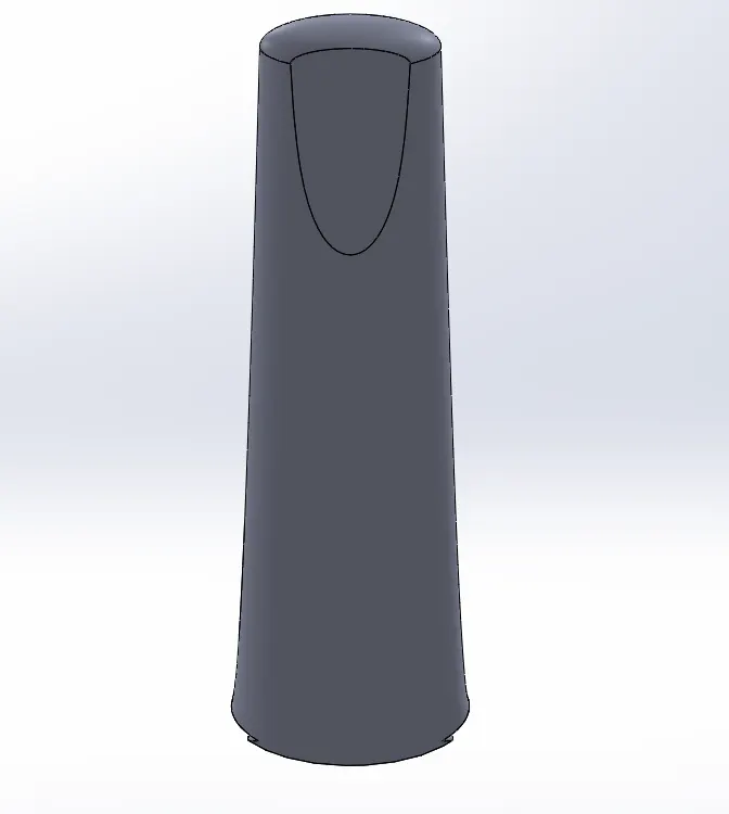
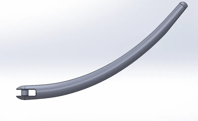
Views of Kickstand:
Front View:
Side View:
Isometric View:
3. Fenders
Front Fender
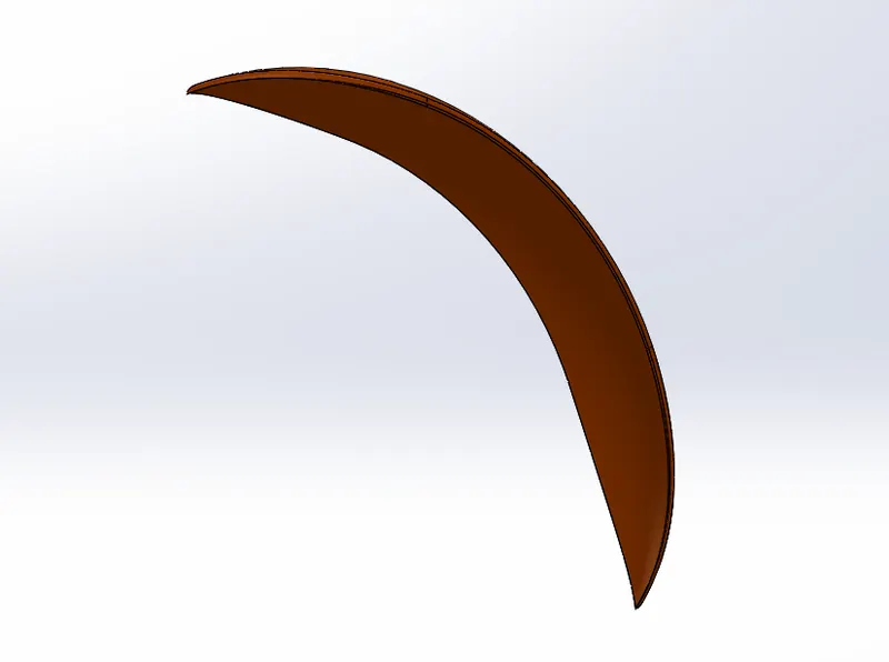
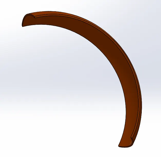
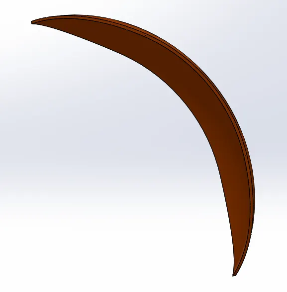
It is the sheet metal part mounted over the roadwheels of an automobile, bicycle etc. It reduces the splashing of mud, water and for clearing the track of obstructions.
Features used to create:
- Sketch
- Revolve: It is the method of defining 3D geometry by revolving a sketched section around a centerline.
- Offset
- Dynamic mirror: It is an excellent tool by which the geometry can be sketched and mirrrored simaultaneously.
- Split
- Fillet
- Appearances
Steps Involved:
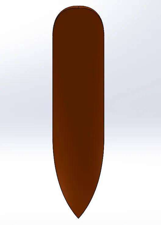
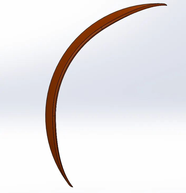
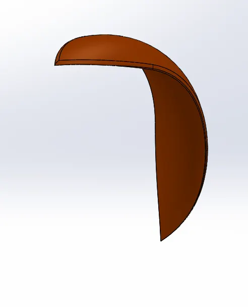
- Sketching a three point arc and use revolve boss command to obtain a revolved part. In this feature, we are giving extrusion to both direction and make it look like a fender structure.
- Using dynamic mirror entities to create a sharp looking edges by sketching spline and mirroring it.
- By applying fillet to make the edges round and giving a siena appearance to fender.
Views of Front Fender:
Front View:
Side View:
Isometric View:
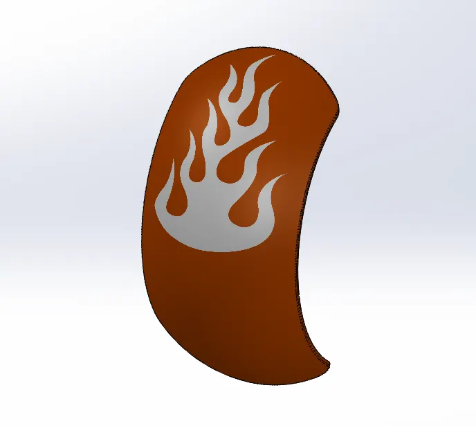
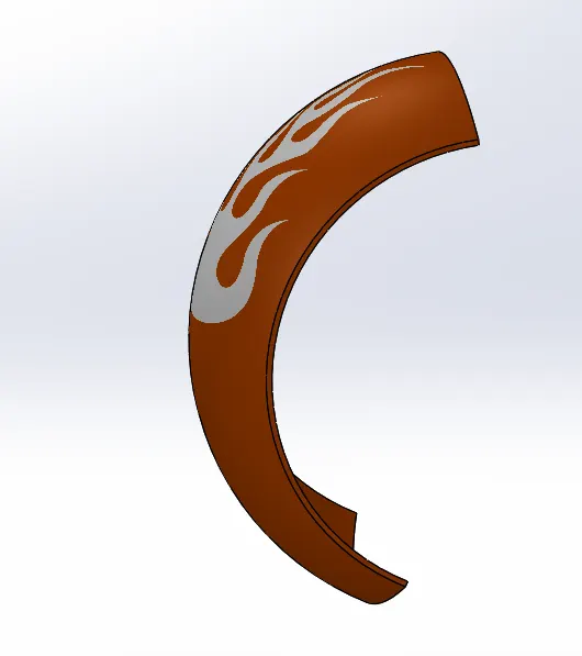
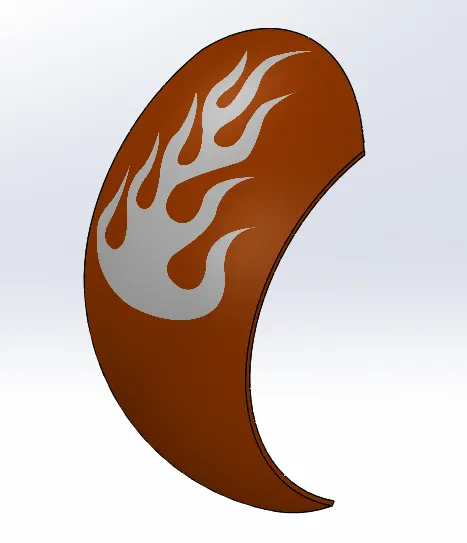
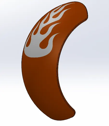
Rear Fender
Features used to create:
- Sketch
- Revolve
- Split
- Fillet
- Shell : The Shell feature hollows out the inside of the solid, leaving a shell of a specified wall thickness.
- Appearances and decals
Steps involved:
- Sketching a 3 point arc and make revolved to both direction.
- Removing material to make a curved edge on both ends so that useing split feature.
- To obtain round edges, fillet option is used and used siena appearances and also apply declas to rear fender.
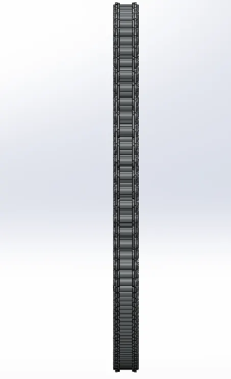
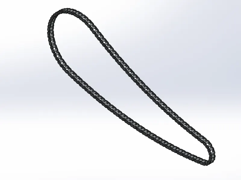
4. Chain
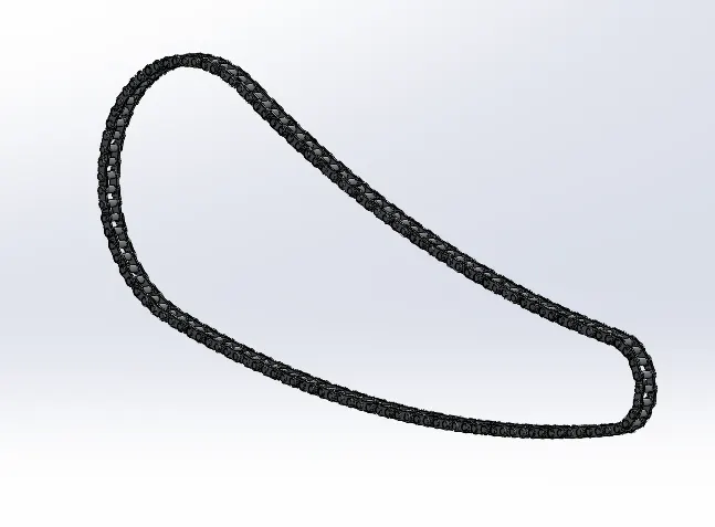
The drive chain of a motorcycle is a very important element of the motorcycle drivetrain. Some bikes also use shafts and belts for the final drive but most motorcycles rely on chain and sprocket setup for the job. The final drive is responsible for transferring the engine power to the rear wheel. Chains must be lubricated to get better performance and if it is unlubricated, then it will decrease performance and increase wear.
Features used to create:
- Sketch
- Fillet
- Extrude Boss
- Appearances
Steps Involved:
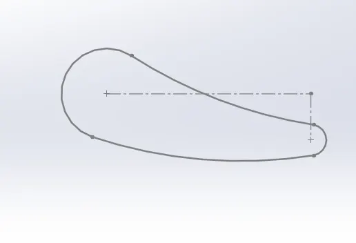
- Sketching 2 circles and connecting them with 3 point arc to obtain the sketch to be modelled.
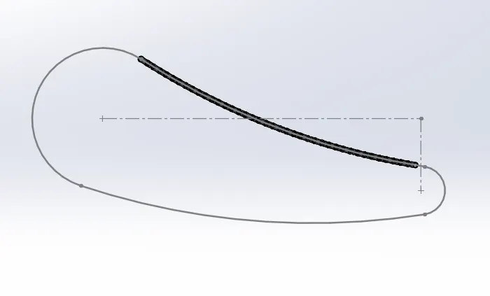
- Chain blocks are to be inserted to the sketch so we construct 2 types of block and insert it.
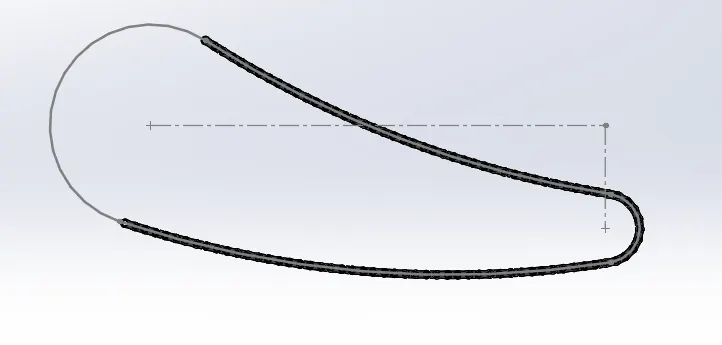
- Arranging them in the sketch so that it would be coming one after the other.
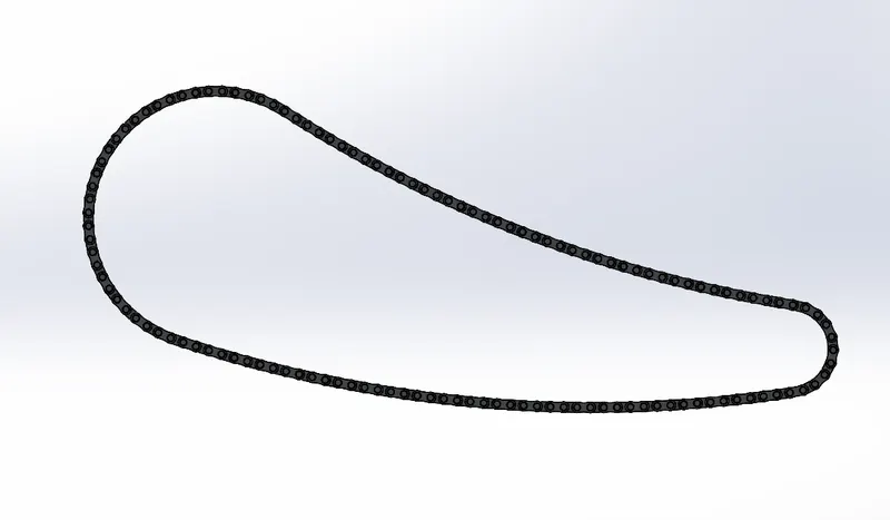
- Inorder to design the chain, we are using curve driven pattern in every arc and use it n number of times.
- Finally using fillet to keep the edges round.
Views of Chain:
Front View:
Side View:
Isometric View:
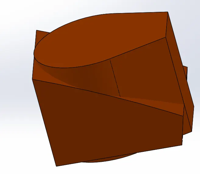
5. Oil Tank
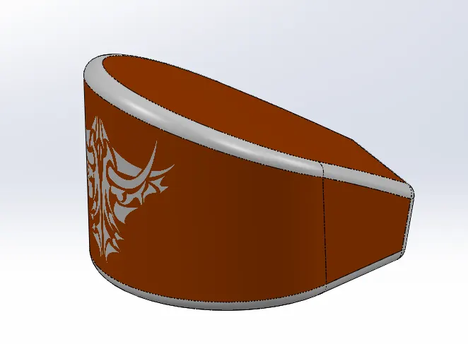
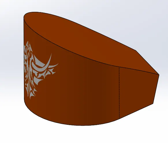
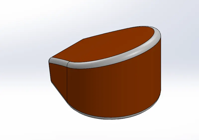
Oil tank is a container type part which holds the oil which helps in coumbustion in engine. Decals are present in oil tank also.
Features used to create:
- Sketch
- Extrude Boss
- Fillet
- Combine : The common function allows you to add two bodies together, and keep the area that is common to them.
- Shell
- Appearance and decals
Steps involved:
- Drawing the sketch and extruding it.
- Selects a plane and draw a sketch and later use combine option to combine both solid bodies which are the parts common to them.
- Adding fillets and applying appearances and decals.
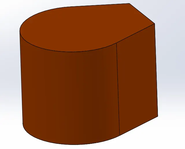
Views of Oil tank:
Front View:
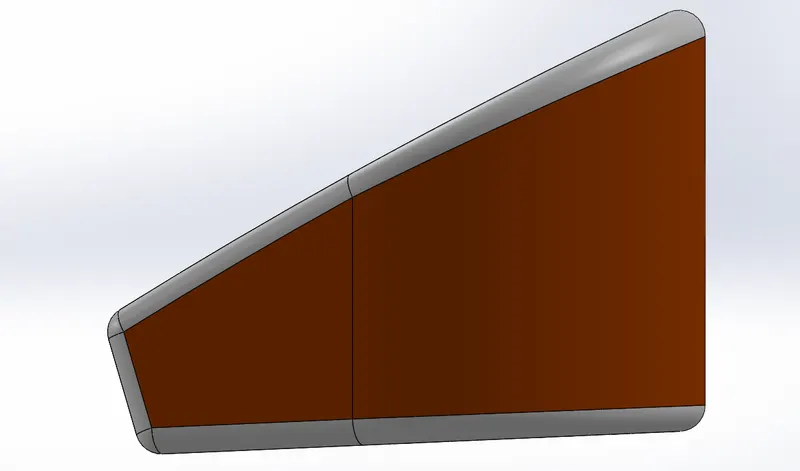
Side View:
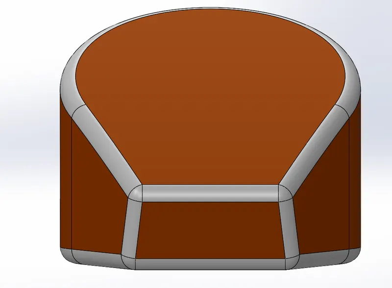
Isometric View:
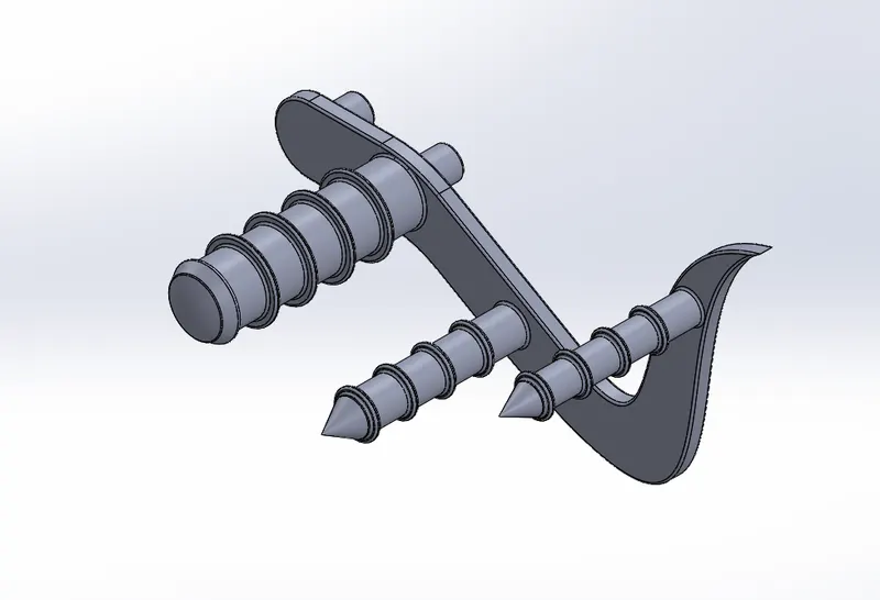
6. Pedal
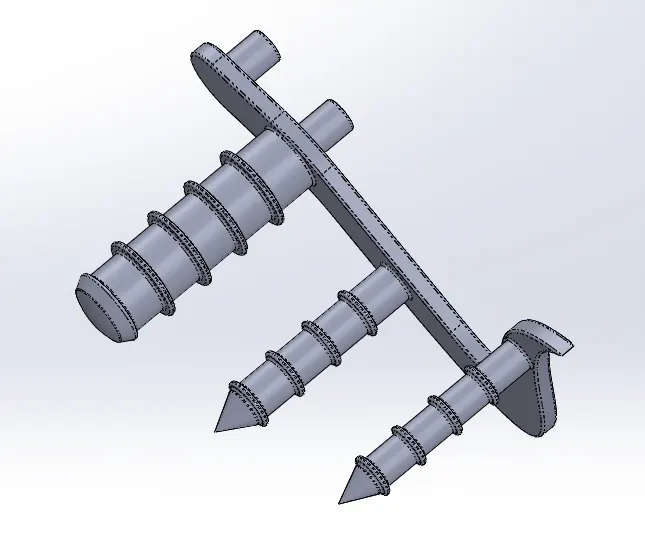
Pedal is the foot rest on the bike.
Features used to create:
- Sketch
- Extrude Boss
- Revolve Boss
- Fillet
- Dome
- Linear Pattern
- Appearances
Steps involved:
- Sketching the line diagram and applying boss extrude.
- Sketching on other face and revolving it.
- Applying dome to a face to make it sherically hemisphered and using linear pattern option to make similar type of threads in the revolved base portion.
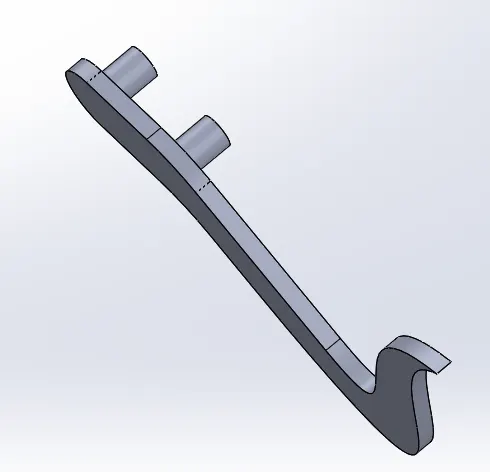
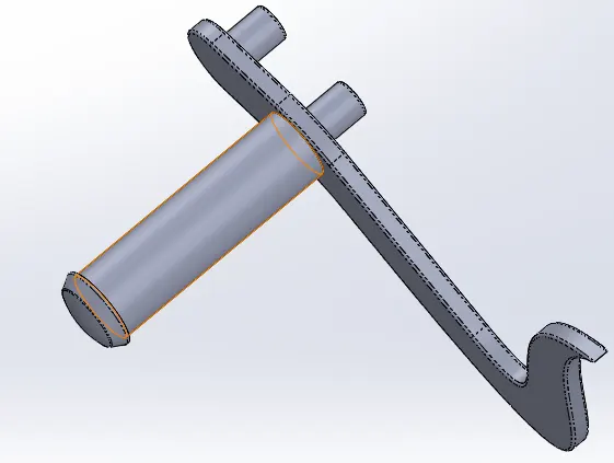
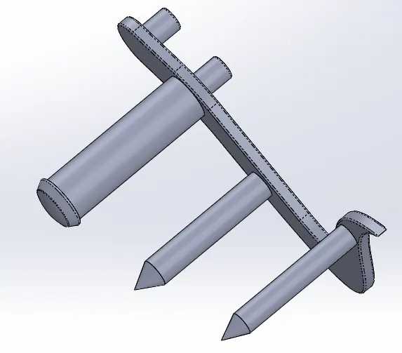
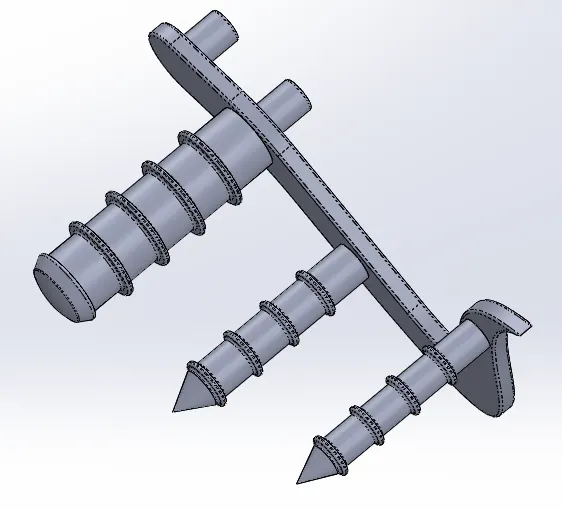
Views of Pedal:
Front View:
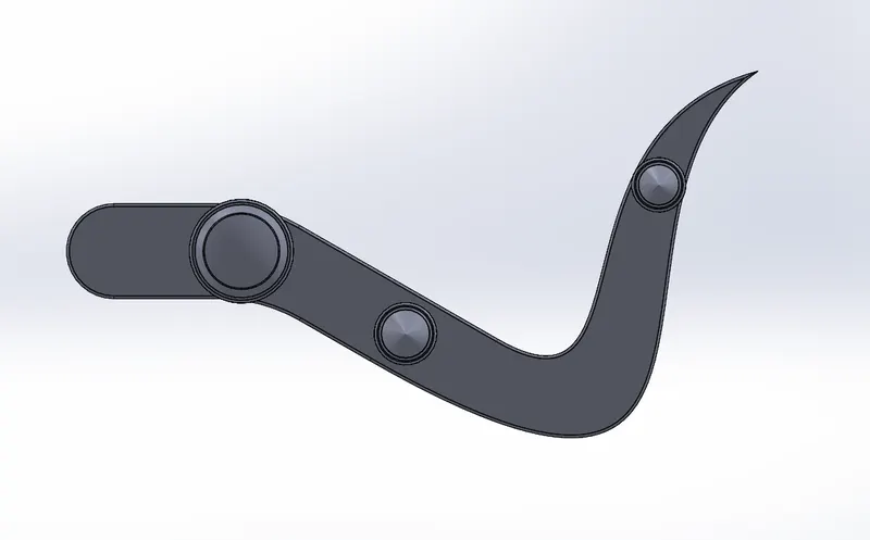
Side View:
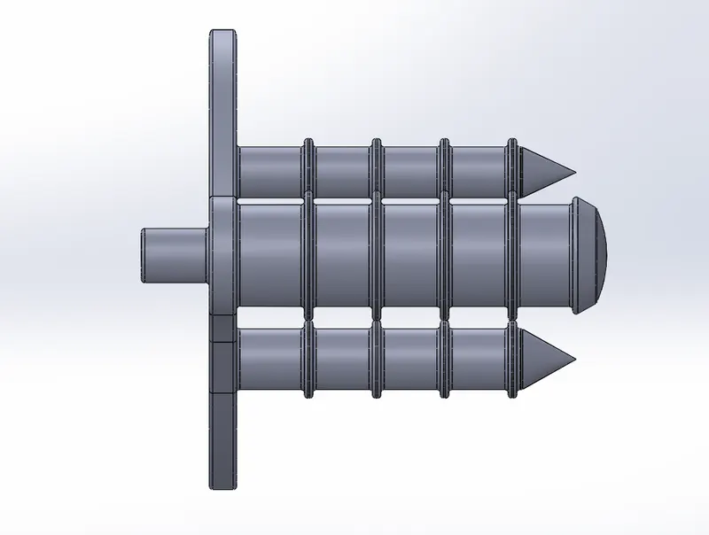
Isometric View:
7. Wheels
Front Wheel
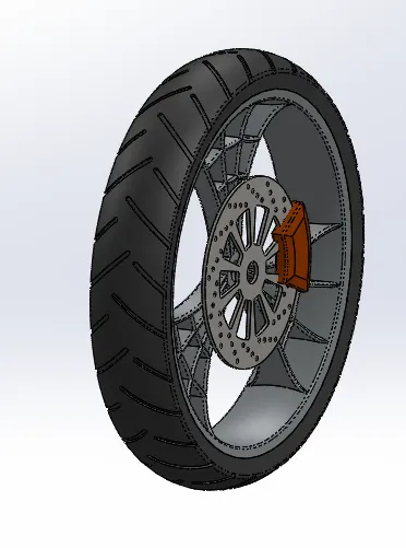
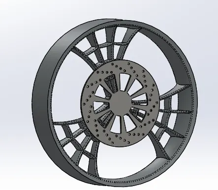
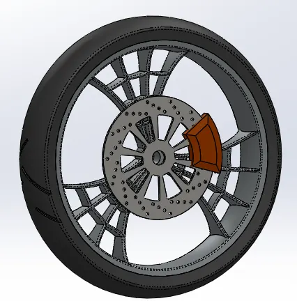
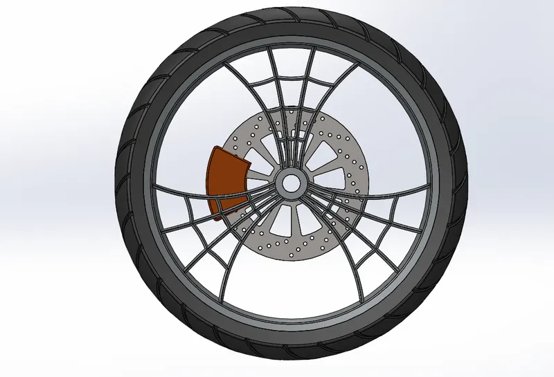
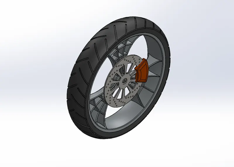
It is a circular object which revolves around the axle and this wheel enables to move the vehicle over the ground. Motorcycle wheels are made to cope with radial and axial forces. They also provide a way of mounting other critical components such as the brakes, final drive and suspension.It consists of following solid bodies.
- Rim
- Rotor
- Caliper
- Tyre
Features used to create:
- Sketch
- Revolve Boss
- Offset
- Mirror
- Extrude Cut
- Revolve Cut
- Circular Pattern
- Chamfer
- Combine
- Trim entities
- Fillet
- Appearances
Steps Involved:
- Sketching the line diagram and revolve it by the centerline and creating spokes at the interior portion by using spline and extruding it.
- Spokes are to be mirrored and constructing the rotor and providing certain pattern and design gaps.
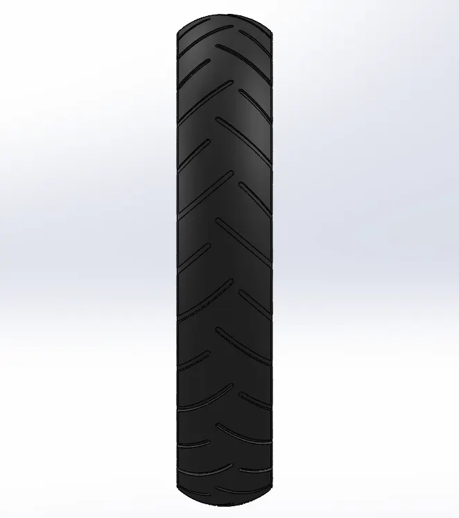
- Providing the caliper and giving tyre portion to the outside surface of the revolve. Sketching the thread sketch on tyre portion and giving circular pattern to make these threads to whole tyre surface.
- Applying siena appearance to the caliper, matte rubber to tyre and chromium to rotor, rim.
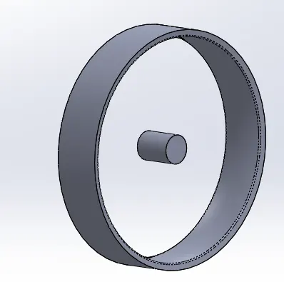
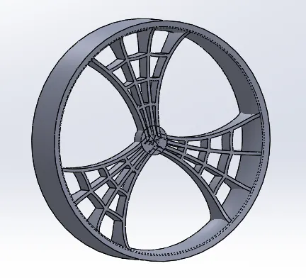
Views of Front Wheel:
Front View:
Side View:
Isometric View:
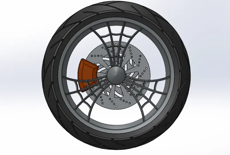
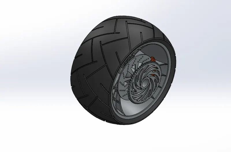
Rear Wheel:
It is located at the back of the vehicle. It consists of following components.
- Rim
- Rotor
- Sprocket
- Caliper
- Tyre
Features used to create:
- Sketch
- Revolve Boss
- Offset
- Mirror
- Extrude Cut
- Revolve Cut
- Circular Pattern
- Chamfer
- Combine
- Trim entities
- Fillet
- Appearances
Steps Involved:
- Sketching the line diagram and revolve it by the centerline and creating spokes at the interior portion by using spline and extruding it.
- Spokes are to be mirrored and constructing the rotor and providing certain pattern and design gaps.
- Sprockets which threads at the outer surface is modelled.
- Providing the caliper and giving tyre portion to the outside surface of the revolve. Sketching the thread sketch on tyre portion and giving circular pattern to make these threads to whole tyre surface.
- Applying siena appearance to the caliper, matte rubber to tyre and chromium to rotor, rim and sprocket.
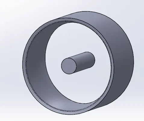
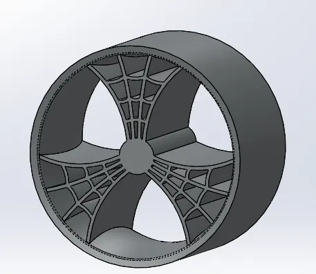
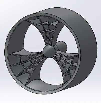
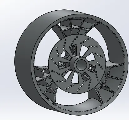
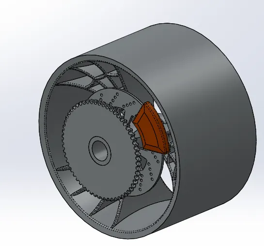
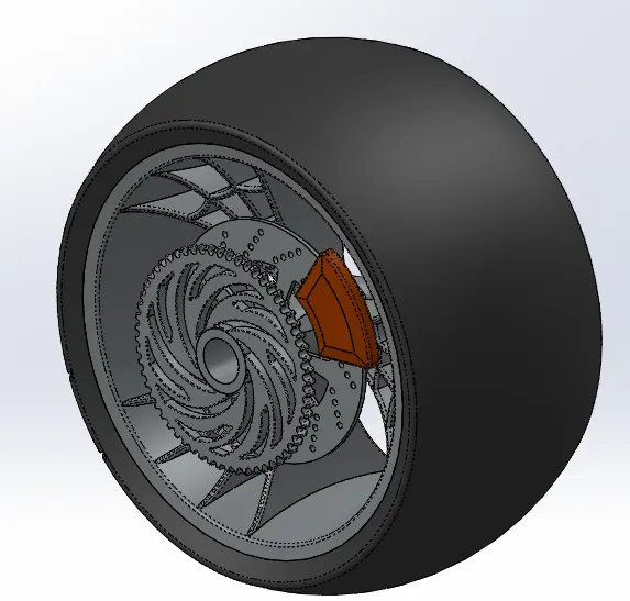
Views of Rear Wheel:
Front Wheel:
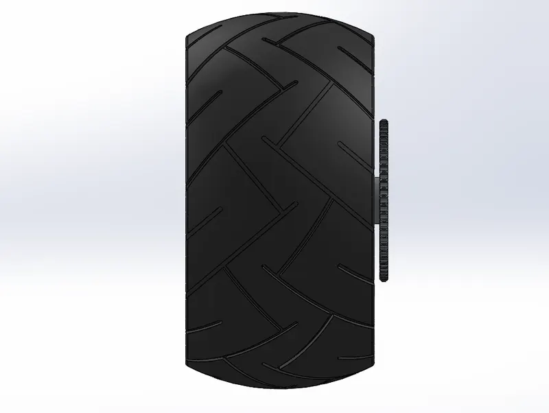
Side View:
Isometric View:
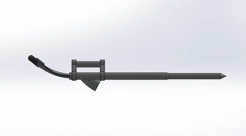
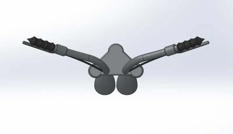
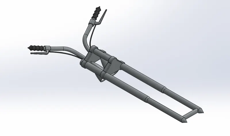
8. Front Fork
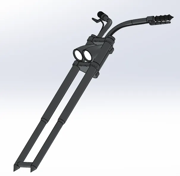
A motorcycle fork connects a motorcycle's front wheel and axle to its frame, typically via a yoke, also known as a triple clamp, which consists of an upper yoke joined to a lower yoke via a steering stem, a shaft that runs through the steering head, creating the steering axis.
Features used to create:
- Sketch
- Revolve Boss
- Extrude Boss
- Fillet
- Linear pattern
- Extrude Cut
- Revolve Cut
- Dome
- Projected Curve
- Sweep
- Mirror
- Combine
- Trim Entities
- Body/ Move or Copy
- Appearances
Steps Involved:
- Draw a sketch to construct revolve boss and extrude the triple clamp at one end of fork tube.Filleting the edges of the triple clamp and applying a linear pattern to get multiple clamps.
- Apply revolve cut to obtain front head light and giving aappropriate extrude cut and fillets and extrude boss for axle.
- To construct the handle we uses projected curve option and sweep tool to obtain the model.Also providing the handle grip and brake pedals merging with the handle.
- Mirroring the entire tube and parts which are merged with tube.
- Providing the appearances to the fork tube to chromium, handle grip and brake cabel to glossy rubber and head light to white area light.
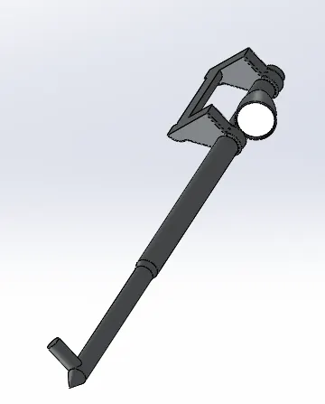
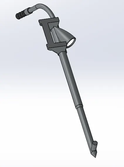
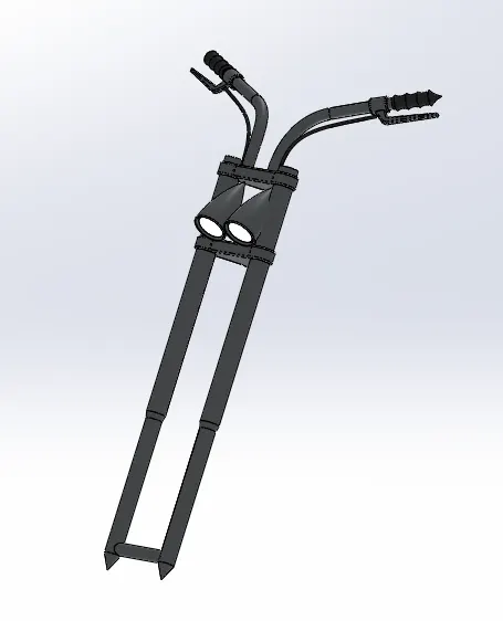
Views of Front Fork:
Front View:
Side View:
Isometric View:
9. Chassis
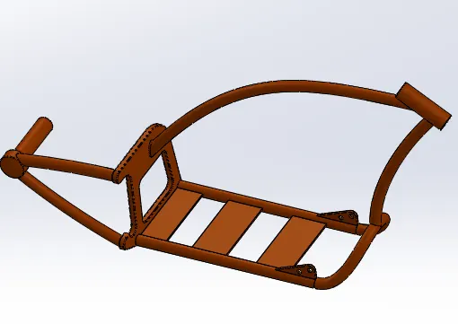
A motorcycle's chassis or frame forms its skeleton. All the components of a motorcycle, like the suspension, wheels, fuel tank, seats, handlebars etc, are attached to this base structure which lends a motorcycle its strength and ability to handle well.It bears all the stresses on the vehicle in both static and dynamic conditions.
Features used to create:
- Sketch
- Sketch Picture
- Projected Curve
- Swept Base
- Mirror
- Convert Entities
- Extrude Boss
- Extrude Cut
- Chamfer
- Fillet
- Split
- Dome
- Revolve Boss
- Combine
- Fillet
- Appearances
Steps Involved:
- Creating the sketch through the blueprint of chopper and projecting curve to get a solid swept part. Mirroring the body with the plane to get in the other side also.
- In the right plane, creating a new sketch by convert entities option and extruding the solid geometry towards outside of the tubings.
- Making extrude cut from the solid geomtry just made and filleting the edges, chamfering the edges, sweep to create the tubes in chassis.
- Using split option and consume bodies we obtain a perfect section which fit the swept portion to perfectly aligned with other two swept tubes.
- Sketching the fork stem and revolve cut it to get a solid tube and uses split tool to remove the tube portion inside the solid body.
- Constructing the base portion of chassis and extruding it and also some additional plates. A pivoting option to hold the kickstand is given.
- The appearance given to whole chassis model is siena.
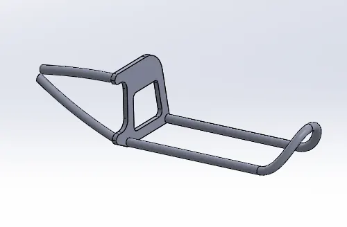
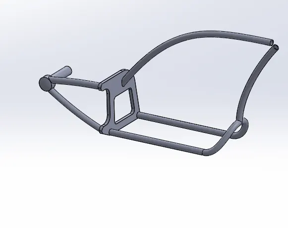
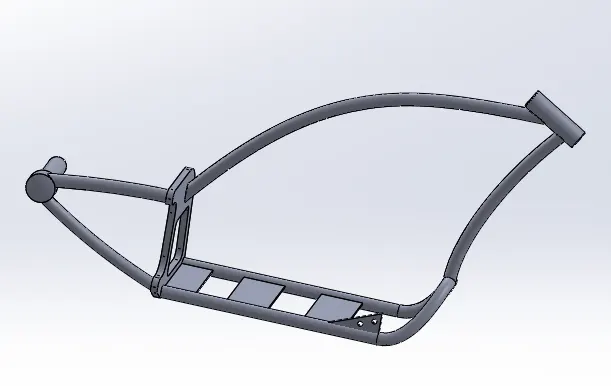
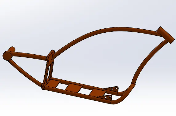
Views of Chassis:
Front View:
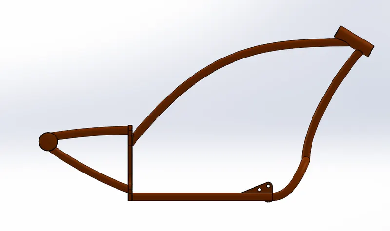
Side View:
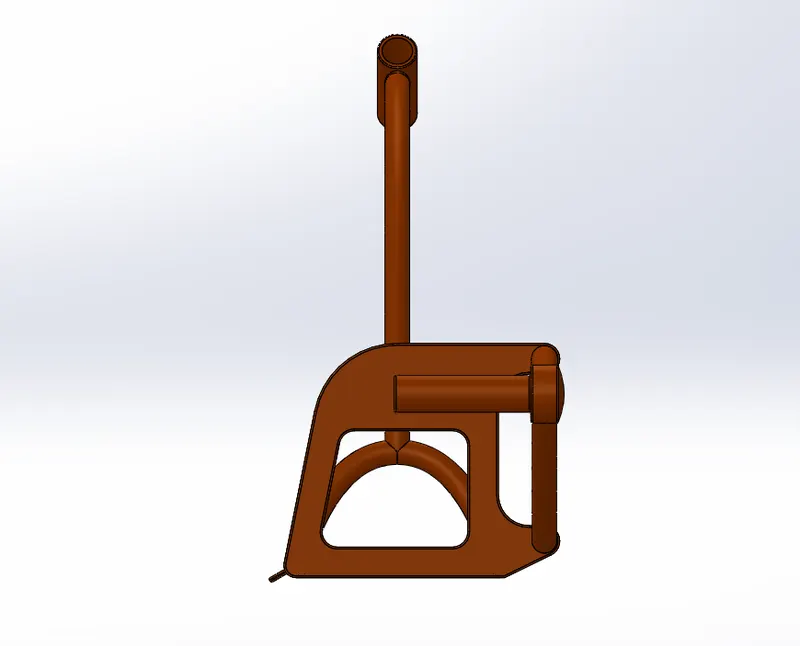
Isometric View:
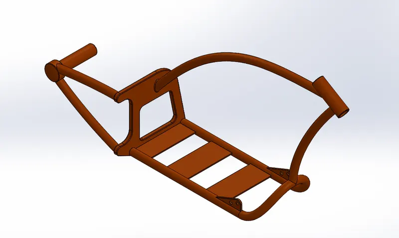
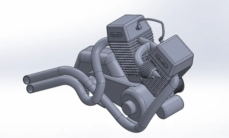
10. Engine
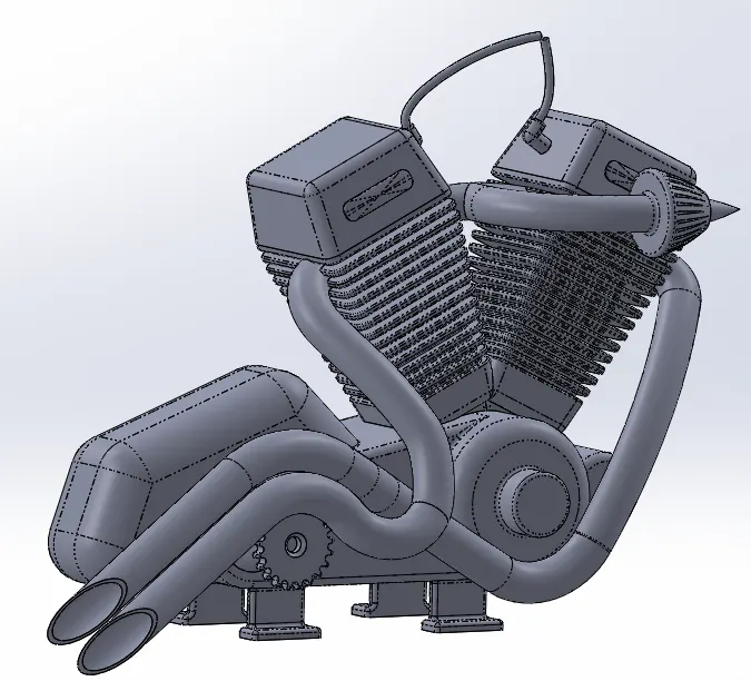
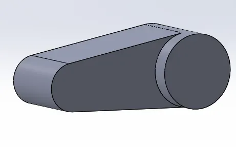
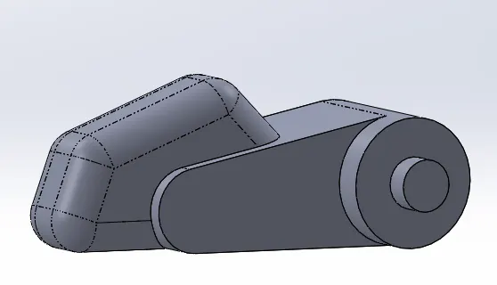
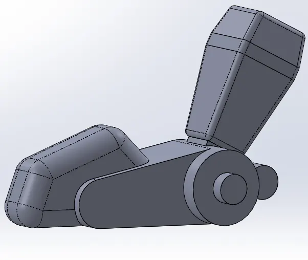
A motorcycle engine is an engine that powers a motorcycle. Motorcycle engines are typically two-stroke or four-stroke internal combustion engines, but other engine types, such as Wankels and electric motors, have been used.
Features used to create:
- Sketch
- Sketch Picture
- Trim
- Combine
- Chamfer
- Fillet
- Swept Boss
- Dome
- Split
- Circular Pattern
- Linear Pattern
- Extrude Cut
- Extrude bose
- Projected curve
- Composite Curve
- Revolve Bose
- Appearances
Steps Involved:
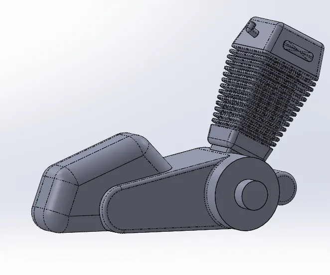
- It is the most complicated structure to be modelled in the american chopper.
- Operations like extrudes bose, revolve boss, extrude cut, mirror, pattern, sweep and various sketches to do these operations are present.
- The most complicated part is the exhaust pipe modelling. It is made by using projected curves and composite curves.Then it converted to a single curve.
- The fins are designed surrounded to 2 cylinders.
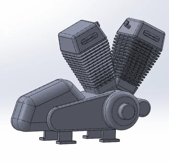
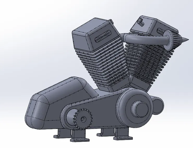
Views of Engine:
Front View:
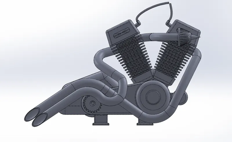
Side View:
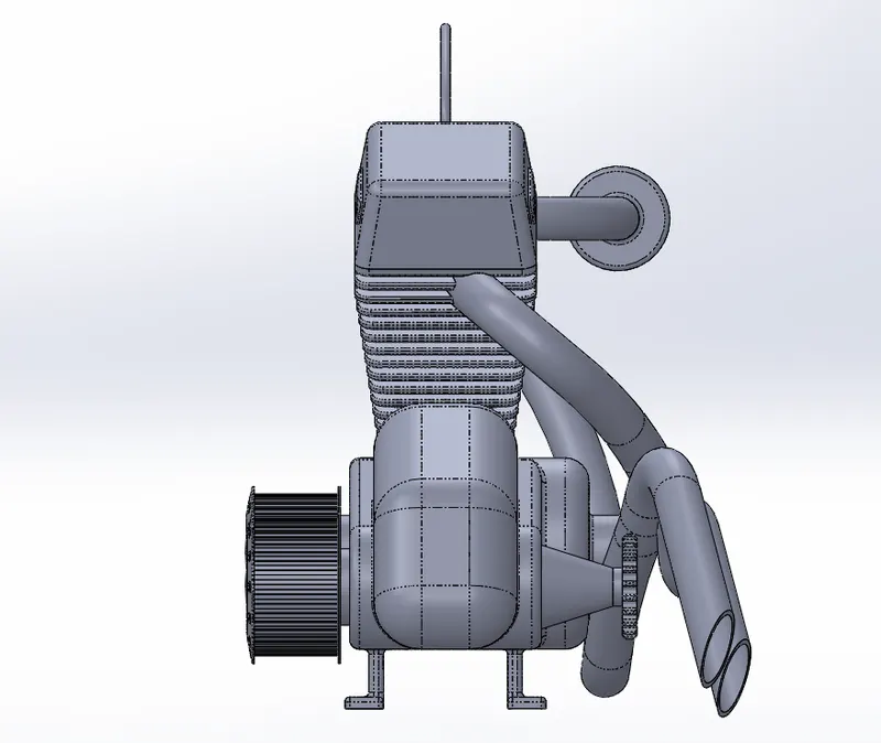
Isometric View:
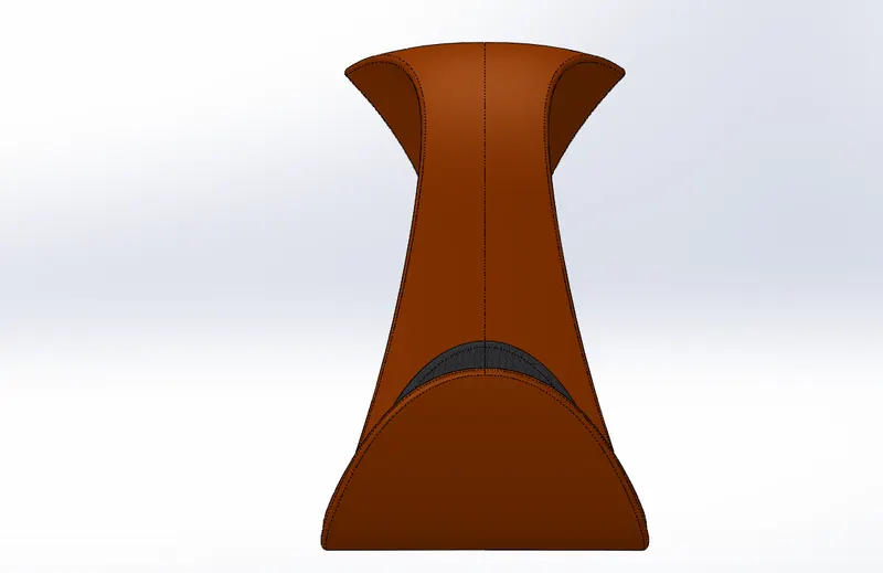
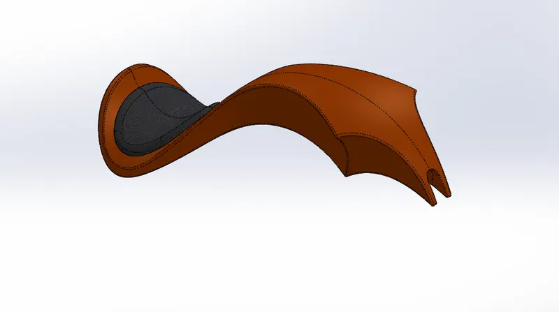
11. Gas Tank
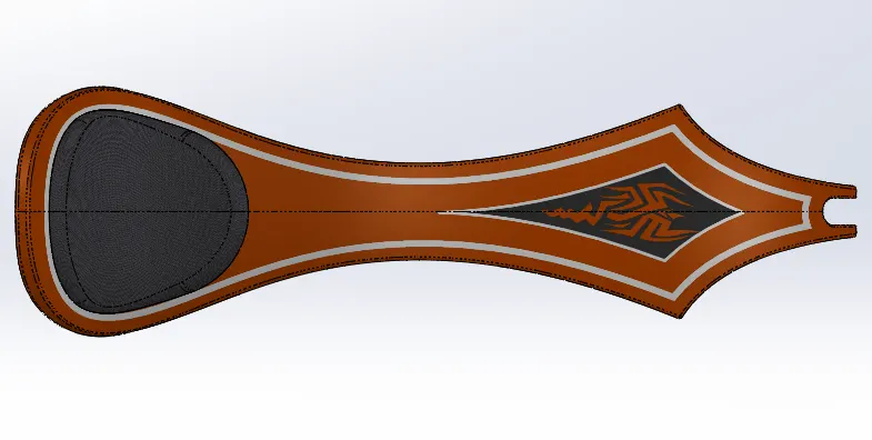
Features used to create:
- Sketch
- Sketch Picture
- Projected Curve
- Split Line
- Surface Trim
- Fillet
- Shell
- Mirror
- Swept Cut
- Lofted surface
- Knit Surface
- Swept Surface
- Extrude Surface
- Boundary Surface
- Appearances and decals
Steps Involved:
- The gas tank sketch is made by projected cruve by using the bleuprint inserted using sketch picture.
- A portion on the gas tank is made for the seat.
- Split line is used and extruded surface is used to get a gas tank appearance.
- Mirroring the same portion about the plane gives a complete structure of gas tank.
- Making it a shell it will be located nicely abouve the engine.
- Appearances and decals are given to make it attractive.
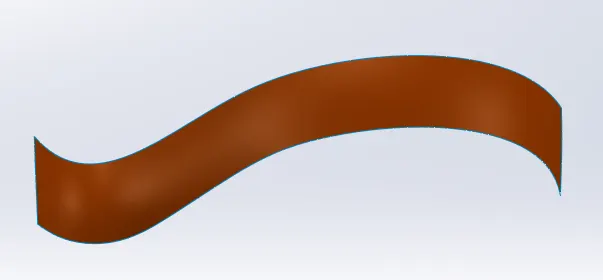
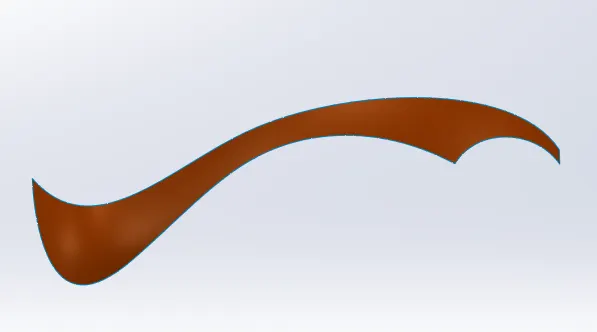
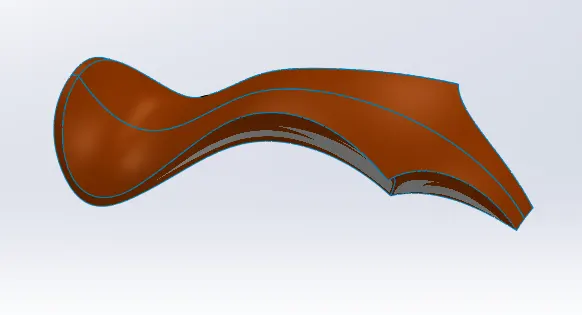
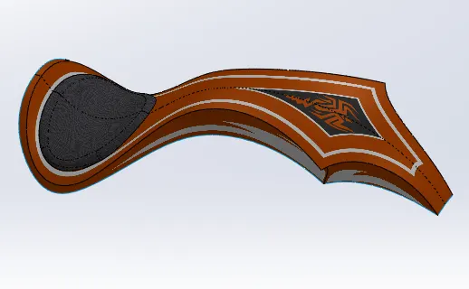
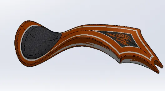
Views of Gas Tank:
Front View:
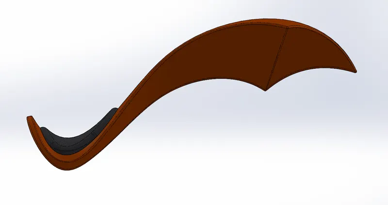
Side View:
Isometric View:
Assembly
Features Used:
- Insert Components
- Mates
Steps Involved:
- Inserting each components according to the order that is to be arranged.
- The first component is chassis to which most of other componenets are mated or fitted.
- The second component is the engine which mated with the chassis.
- These components are mated by various relationships such as coincident, tangents, concentric etc.
- After all decals are provided.
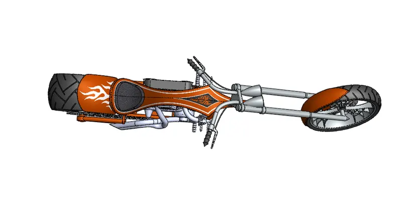
Views of Assembly:
Front View:
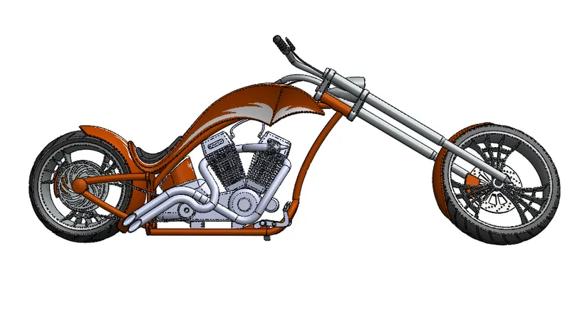
Side View:
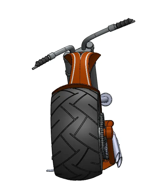
Isometric View:
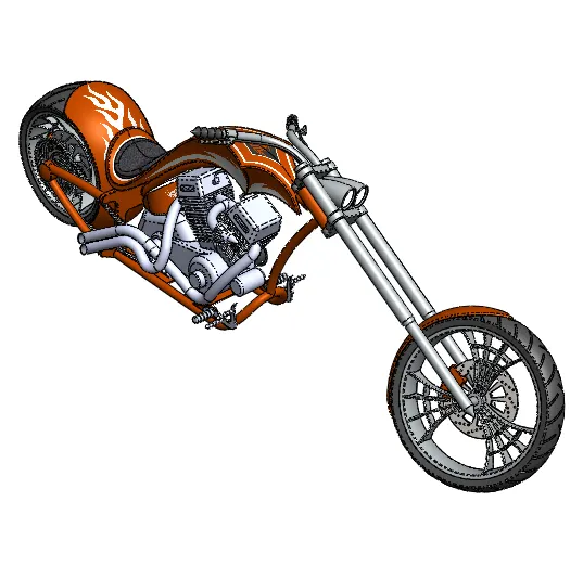
Camera View:
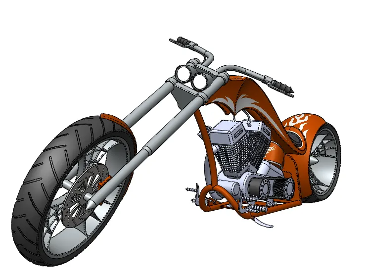
Top View:
Photorealistic Rendered Images:
Conclusion:
Every parts of the American chopper has been modelled and assembly is done also the photorealistic rendered images are also obtained.