Project 1 - 2D meshing on the instrumental Panel
AIM
- To extract the midsurface of the given component & to carry out necessary geometry cleanup operations.
- To mesh the extracted midsurface and to validate the FE model based on the given quality criteria.
- To assign the appropriate thickness to the FE model.
PROCEDURE
- Before modelling, it is necessary to clean the parent geometry for irregularities and errors. The 'Topo' tool is used to fix the single cons problem as shown in the image below.
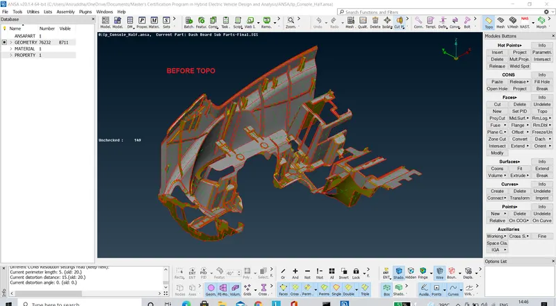
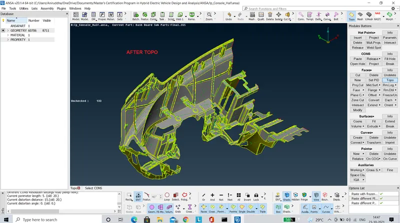
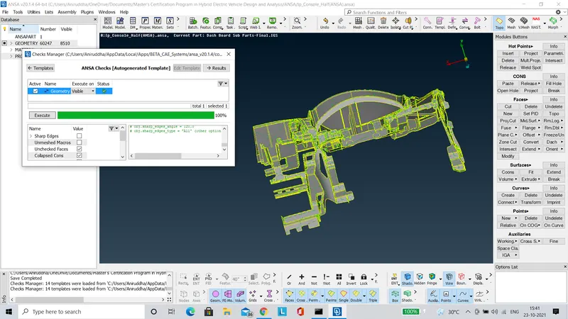
- Using the 'Geometry Check' option we can identify the hidden geometric errors present in the component and accordingly fix them.
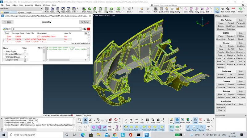
- The surface discontinuities are fixed using the 'New' tool under the 'Faces' panel as shown in the images below.
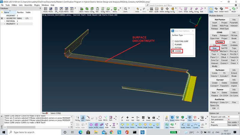
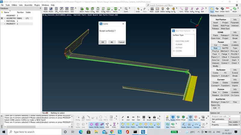
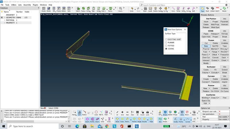
- The 'Geometry Check' tool is run again to verify that all irregularities have been resolved.
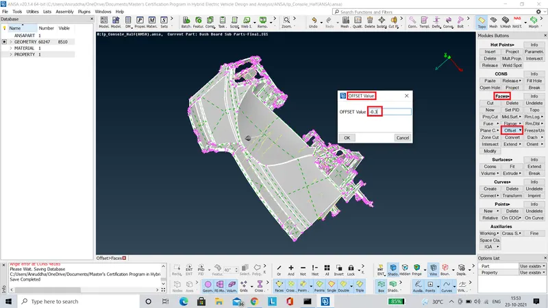
- The midsurface is extracted manually using the 'Offset' tool, by assigning the appropriate thickness such that the midsurface is generated on the neutral plane.
- When it comes to the ribs, each surface is extracted seperately based on their individual thickness as shown in the images below.
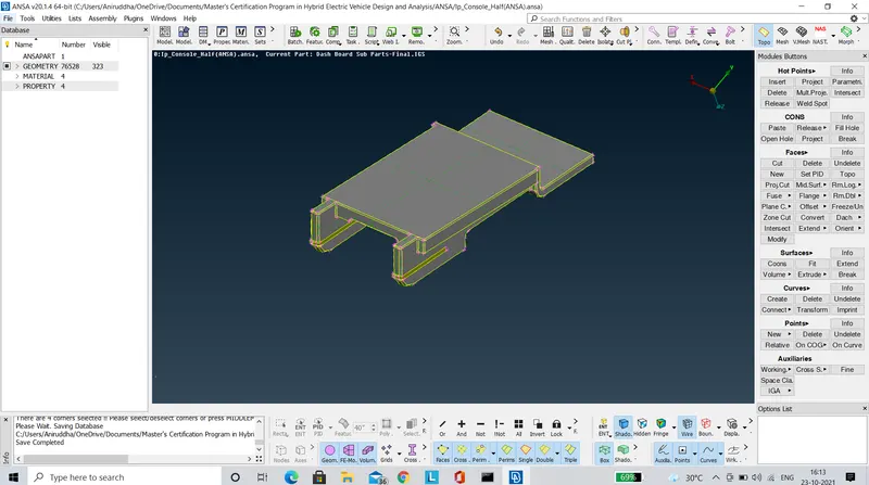
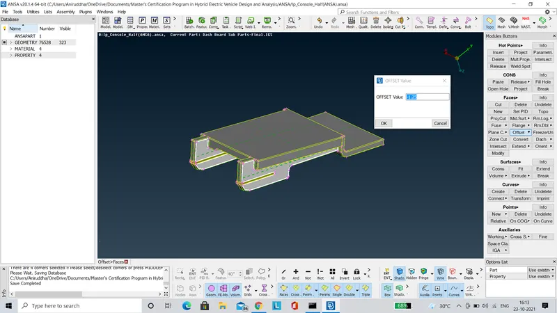
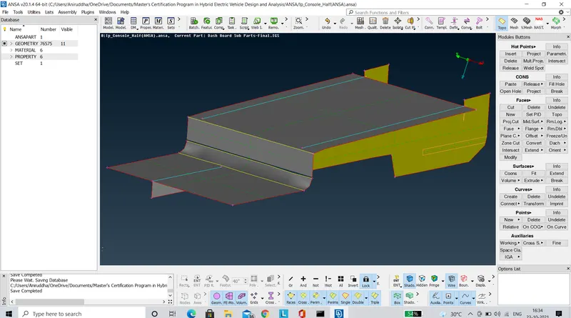
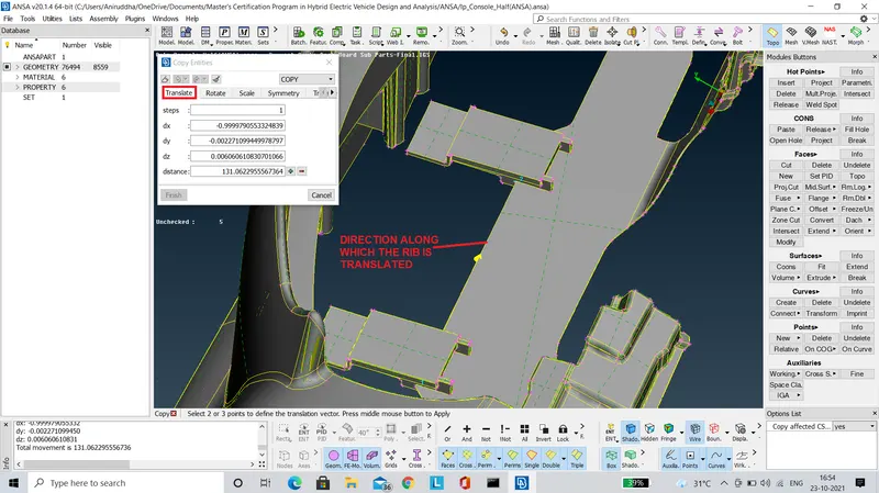
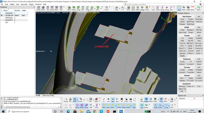
- Ribs of similar shapes and dimensions are copied at appropriate locations by using the 'Translate' tool as shown in the images below.
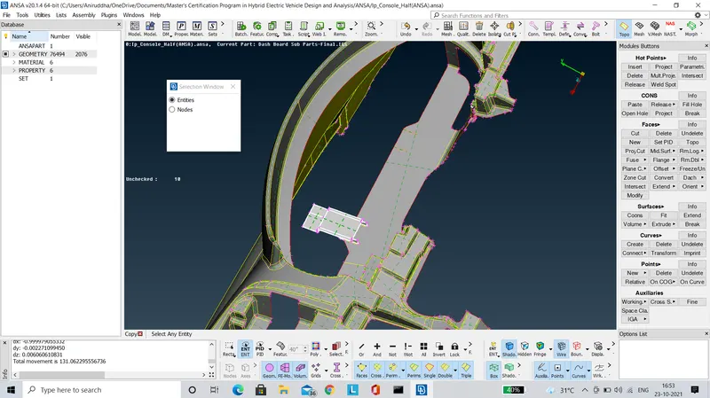
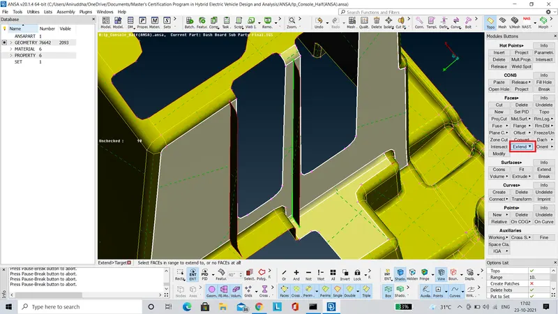
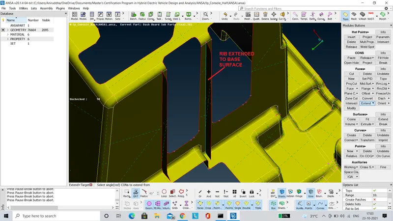
- The ribs extracted individually, are extended to the base surface as shown in the images below.
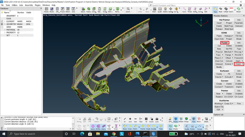
- Using the 'Orient' tool it is made sure that all the faces of the component are in the appropriate orientation as shown below.
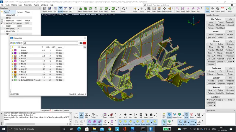
- The various surfaces are differentiated under different PID's based on their thickness as shown in the image below.
- Finally it is necessary to assign the given quality criteria and mesh parameters as shown in the images below.
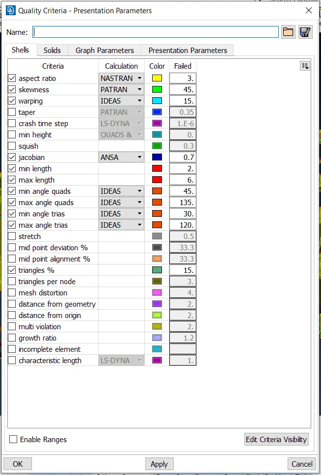
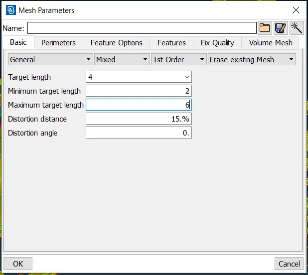
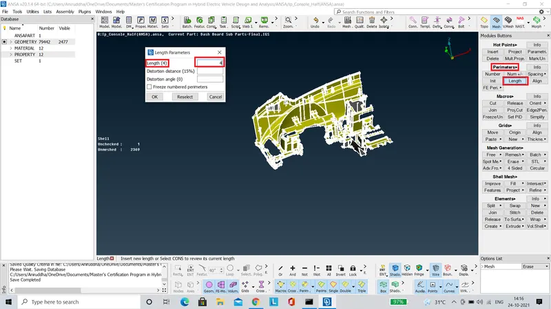
- Using the 'Length' tool under the 'Perimeters' panel of 'Mesh' deck, the edge length of the midsurface is portioned as per the target element length provided.
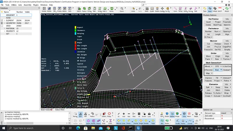
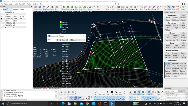
- While meshing the midsurface, each surface of the component is meshed seperately using the 'Best' tool present under the 'Mesh Generation' panel of 'Mesh' module. The regions where the the mesh is not refined are remeshed using the 'Reconstruct' tool.
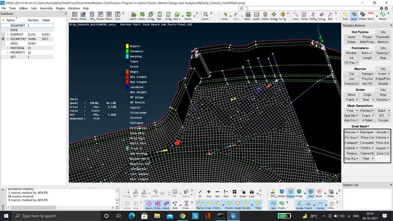
- Since we are preparing this model for crash and safety simulations, we have to avoid rotating quads at any cost. The tria elements are acceptable but should not conflict with each other ie. adjacent trias and trias facing opposite to each other should be avoided.
- The conflicting trias can be rectified using the 'Spilt', 'Join' & 'Paste' tools. Finally the 'Smooth' tool is used to improve the uniformity of the generated mesh.
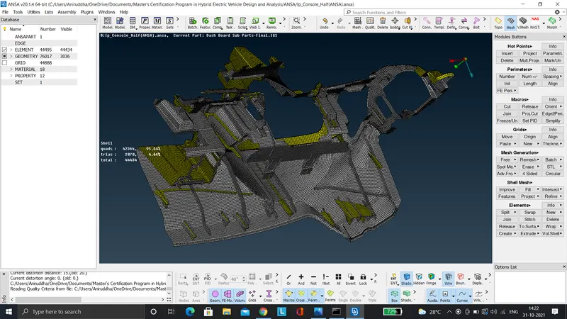
- Finally the 'Draw shell as solid' checkbox present in the 'Quality Criteria' icon should be selected to visualise the 2D shell element as a solid.
LEARNING OUTCOME
- The various tools concerned with geometry cleanup, midsurface extraction, & mesh generation were learnt during the course of this project.
CONCLUSION
- The model of an instrumental panel of a car provided, has been meshed as per the given quality criteria and the appropriate thickness has been assigned to visualise the shell element as a solid.